
Related Manuals for Sony FCB-CX20DP


Summary of Contents for Sony FCB-CX20DP
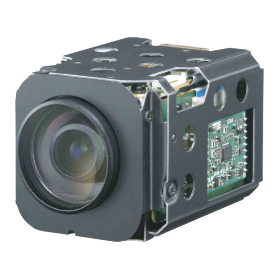
- Page 1 A-D98-100-11(1) Color Camera Module Technical Manual FCB-CX20DP (PAL) 2009 Sony Corporation...
-
Page 2: Table Of Contents
Table of Contents Features ..............3 Precautions ..............4 Locations of Controls ..........6 Basic Functions ............7 Overview of Functions ..........7 Eclipse ..............20 Spectral Sensitivity Characteristics ......20 Vibration Specifications ..........20 Key Switch Circuitry ..........21 Key Function Specifications ........ -
Page 3: Features
Overview Features • The Type Super HAD II CCD features 440,000 effective picture elements and high-sensitivity shooting. The minimum illumination required is 0.25 lux. • 10× optical zoom (120× with digital zoom) • Supporting external synchronization (V-lock) • Images with a high resolution (530 TV lines) can be obtained using a newly developed DSP for improved picture quality. -
Page 4: Precautions
Precautions In case of abnormal operation, contact your authorized Software Sony dealer or the store where you purchased the Use of the demonstration software developed by Sony product. Corporation or use of the software with customer developed application software may damage hardware, Phenomena specific to CCD image the application program or the camera. - Page 5 Precautions Phenomena specific to the lens Lens flare Bright light sources and other shooting conditions may cause light reflection to occur inside the camera lens and result in lens flare. Shading The corners of images may appear darker in some situations.
-
Page 6: Locations Of Controls
Locations of Controls Locations of Controls Front Back Bottom 1 Lens 5 Tripod screw hole 2 CN602 jack When a tripod is used, please use 6 mm ( in.) or less screw to 3 CN601 jack attach it to the camera. Also, 4 CN801 jack (for key SW) please be sure to attach the tripod securely. -
Page 7: Basic Functions
Basic Functions Basic Functions In general Overview of Functions • Power On/Off Powers the camera on and off. When the power is off, VISCA commands are the basis of camera control. the camera is able to accept only the lowest level of VISCA Commands;... - Page 8 Basic Functions Zoom Focus The FCB camera employs a 10× optical zoom lens Focus has the following modes, all of which can be set combined with a digital zoom function; this camera using VISCA Commands. allows you to zoom up to 120×. •...
- Page 9 Basic Functions • Bright White Balance Variable Iris and Gain (Close to F1.8, 17 steps at White Balance has the following modes, all of which 0 dB: F1.8, 15 steps from 0 to 28 dB) can be set using VISCA Commands. AE –...
- Page 10 Basic Functions AE – Manual When switching from the Shutter Priority mode to the The shutter speed (22 steps), iris (18 steps) and gain Bright mode, the shutter speed set in the Shutter (16 steps) can be set freely by the user. Priority mode is maintained.
- Page 11 Basic Functions Exposure Compensation High Resolution Mode (Default) Exposure compensation is a function which offsets the A newly developed DSP function enables the filtering internal reference brightness level used in the AE of signals. This allows the camera to provide images mode, by steps of 1.5 dB.
- Page 12 Basic Functions Auto ICR Mode Effect Auto ICR Mode automatically switches the settings It consists of the following functions. needed for attaching or removing the IR Cut Filter. • Neg. Art: Negative/Positive Reversal With a set level of darkness, the IR Cut Filter is •...
- Page 13 Basic Functions User Memory Area A user area of 16 bytes allows you to write data, such as an ID for each customer, data for each system, and so on, freely. Note Rewriting of memory is not unlimited. Be careful to avoid using the memory area for such as unnecessary tasks as rewriting the contents of the memory for every operation.
- Page 14 Basic Functions Privacy Zone Masking Function Features • Mask can be set on up to 24 places according to Pan/ Privacy Zone masking protects private objects and Tilt positions. areas such as house windows, entrances, and exits • Mask can be displayed on 8 places per screen which are within the camera’s range of vision but not simultaneously.
- Page 15 Basic Functions Privacy Zone Setting Command List Command Packet Command Set Command Comments CAM_PrivacyZone SetMask Setting Mask(Size) 8x 01 04 76 mm nn See “mm: Mask setting list”, “nn: Setting”, and 0r 0r 0s 0s FF “pp: x, qq:y, rr: w, ss: h” in “Parameters” on page 16.
- Page 16 Basic Functions Parameters mm: Mask setting list nn:Setting Mask Name mm (Hex) Setting Mask Name mm (Hex) Mask_A Resetting the zone size (the value of w,h) Mask_M for the existing mask. Mask_B Mask_N Setting newly the zone size (the value of Mask_C Mask_O w,h).
- Page 17 Basic Functions Comments: Two different color masks can be Details of Setting Commands chosen. Set Mask The colors can be chosen from among 14 colors Command: 8x 01 04 76 mm nn 0r 0r 0s 0s FF including the possibility for semi-transparency of Parameters: each color.
- Page 18 Basic Functions Non Interlock Mask Motion Detection Function Command: 8x 01 04 6F mm 0p 0p 0q 0q 0r 0r 0s 0s This function instructs the camera to detect movement Parameters: within the monitoring area and then send an alarm signal automatically.
- Page 19 Basic Functions • When multiple motions are detected or motion is Sending Alarms detected in another frame within the set interval • When motion is detected, the Alarm Replay following the original time the alarm was issued, command is issued via the serial command (VISCA) another alarm command is not issued.
-
Page 20: Eclipse
Basic Functions Eclipse Vibration Specifications When designing the housing, refer to the dimensional allowance as shown in the figure below. Test Method (Random vibration) • Fix the camera at the four fixation points of the base using M2 screws. • Perform the random vibration test under the following conditions in the X, Y and Z directions for 20 minutes in each direction. -
Page 21: Key Switch Circuitry
For more information, refer to the command list, check functions on the camera, or contact your Sony dealer. 1) The CN101 is connected to the CN801 on the FCB camera main unit. -
Page 22: Key Function Specifications
Basic Functions Key Function Specifications Classification Name Function Button operation Mode display ZOOM WIDE Move ZOOM to WIDE side quickly. Pressing repeatedly allowed. ZOOM bar displayed for 3 s. WIDE SLOW Move ZOOM to WIDE side slowly. Pressing repeatedly allowed. ZOOM bar displayed for 3 s. - Page 23 Basic Functions Classification Name Function Button operation Mode display FEATURE FREEZE Capture still image. Switch on/off. FREEZE indication Horizontal reversal Switch on/off. Horizontal reversal REVERSE indication BLACK & Black-and-white output Switch on/off. B&W display WHITE NEGA ART Negative art output Switch on/off.
-
Page 24: Initial Settings, Custom Preset And Backup
Basic Functions Initial Settings, Custom Preset and Backup Initial settings for the various functions of the FCB camera are indicated in the “Initial settings” column. The “Custom preset” column indicates whether the custom preset function can be used to store the settings. - Page 25 Basic Functions Custom Back up Mode/Position setting Initial settings preset at standby Camera Memory Same as the initial value setting Display On/Off × × Mute On/Off Title Display On/Off Title Setting — Mask Setting — Mask Display On/Off Mask Color Setting —...
-
Page 26: Mode Condition
Basic Functions... - Page 27 Basic Functions...
- Page 28 Basic Functions...
-
Page 29: Command List
SOFTWARE) AND SPECIFICALLY DISCLAIMS ANY LIABILITY FOR ANY SUCH MALFUNCTION OR DAMAGE. THIS CONTROL PROTOCOL AND COMMAND LIST SHOULD BE USED WITH CAUTION..............................................1) VISCA is a protocol which controls consumer camcorders developed by Sony. “VISCA” is a trademark of Sony Corporation. - Page 30 Command List VISCA Communication assigned address 2 is 82H. In the command list, as the header is 8X, input the address of the camera at X. The Specifications header of the reply packet from the camera assigned address 1 is 90H. The packet from the camera assigned VISCA packet structure address 2 is A0H.
- Page 31 Command List Responses for commands and inquiries Command execution cancel ● ACK message To cancel a command which has already been sent, Returned by the FCB camera when it receives a send the Cancel command as the next command. To command.
- Page 32 CAM_VersionInq 8X 09 00 02 FF Y0 50 GG GG HH HH JJ JJ KK FF GGGG = Vender ID (0020: Sony) HHHH = Model ID 044F: FCB-CX20DP JJJJ = ROM revision KK = Maximum socket #(02) X = 1 to 7: FCB camera address (For inquiry packet)
- Page 33 Command List VISCA Command/ACK Protocol Command Command Message Reply Message Comments General Command 81 01 04 38 02 FF 90 41 FF (ACK)+90 51 FF Returns ACK when a command has been accepted, and (Example) (Completion) Completion when a command has been executed. 90 42 FF 90 52 FF 81 01 04 38 FF...
- Page 34 Command List VISCA Camera-Issued Messages ACK/Completion Messages Comments Command Messages z0 4y FF Returned when the command is accepted. (y: Socket No.) Completion z0 5y FF Returned when the command has been executed. (y: Socket No.) z = Device address + 8 Error Messages Comments Command Messages...
-
Page 35: Fcb Camera Commands
Command List FCB Camera Commands Command List (1/5) Command Set Command Command Packet Comments AddressSet Broadcast 88 30 01 FF Address setting IF_Clear Broadcast 88 01 00 01 FF I/F Clesr CommandCancel 8x 2p FF p: Socket No.(= 1or 2) CAM_Power 8x 01 04 00 02 FF Power ON/OFF... - Page 36 Command List Command List (2/5) Command Set Command Command Packet Comments CAM_WB Auto 8x 01 04 35 00 FF Normal Auto Indoor 8x 01 04 35 01 FF Indoor mode Outdoor 8x 01 04 35 02 FF Outdoor mode One Push WB 8x 01 04 35 03 FF One Push WB mode 8x 01 04 35 04 FF...
- Page 37 Command List Command List (3/5) Command Set Command Command Packet Comments CAM_AE_Response DIRECT 8x 01 04 5D pp FF pp: 01 to 20 (hex) Default value: 01 CAM_SpotAE 8x 01 04 59 02 FF Spot Automatic Exposure Setting 8x 01 04 59 03 FF Position 8x 01 04 29 0p 0q 0r 0s FF pq: X (0 to F), rs: Y (0 to F)
- Page 38 Command List Command List (4/5) Command Set Command Command Packet Comments CAM_Title Title Set1 8x 01 04 73 1L 00 nn pp L: Line Number, nn: H-position qq rr 00 00 00 00 00 FF pp: Color, qq: Blink rr: Opening Title Title Set2 8x 01 04 73 2L mm nn pp L: Line Number,...
- Page 39 Command List Command List (5/5) Command Set Command Command Packet Comments CAM_MD 8x 01 04 1B 02 FF Motion Detection On/Off 8x 01 04 1B 03 FF Function Set 8x 01 04 1C 0m 0n 0p 0q 0r 0s FF m: Display mode n: Detection Frame Set (0 to F) pq: Threshold Level (00 to FF)
- Page 40 Command List Inquiry Command List (1/3) Inquiry Command Command Packet Inquiry Packet Comments CAM_PowerInq 8x 09 04 00 FF y0 50 02 FF y0 50 03 FF CAM_ZoomPosInq 8x 09 04 47 FF y0 50 0p 0q 0r 0s FF pqrs: Zoom Position CAM_DZoomModeInq 8x 09 04 06 FF...
- Page 41 Command List Inquiry Command List (2/3) Inquiry Command Command Packet Inquiry Packet Comments CAM_ApertureInq 8x 09 04 42 FF y0 50 00 00 0p 0q FF pq: Aperture Gain CAM_HRModeInq 8x 09 04 52 FF y0 50 02 FF On Hi-Resolution y0 50 03 FF CAM_LR_ReverseModeInq 8x 09 04 61 FF...
- Page 42 Command List Inquiry Command List (3/3) Inquiry Command Command Packet Inquiry Packet Comments CAM_MDModeInq 8x 09 04 1B FF y0 50 02 FF y0 50 03 FF CAM_MDFunctionInq 8x 09 04 1C FF y0 50 0m 0n 0p 0q FF m: Display mode n: Detection Frame Set (0 to F) pq: Threshold Level (0 to FF)
- Page 43 Command List Block Inquiry Command List Lens Control System Inquiry Commands ....Command Packet 8x 09 7E 7E 00 FF Byte Comments Byte Comments Byte Comments Destination Address Source Address Focus Near Limit (H) 0 Completion Message (50h) DZoomMode 0: Combine 1: Separate 0: Normal 1: Interval 2: Zoom Trigger...
- Page 44 Command List Camera Control System Inquiry Commands ..Command Packet 8x 09 7E 7E 01 FF Byte Comments Byte Comments Byte Comments Destination Address Gain Position Source Address WB Mode 0 Completion Message (50h) Bright Position Aperture Gain Exposure Mode Exposure Comp.
- Page 45 Command List Other Inquiry Commands ........Command Packet 8x 09 7E 7E 02 FF Byte Comments Byte Comments Byte Comments Destination Address External Lock 1: Provided 0: Not provided Memory 1: Provided 0: Not provided Source Address Clock 1: Provided 0: Not provided ICR 1: Provided 0: Not 0 Completion Message (50h)
- Page 46 Command List Enlargement Function Query Command ....Command Packet 8x 09 7E 7E 03 FF Byte Comments Byte Comments Byte Comments Destination Address Advanced Privacy AF Interval Time (H) Source Address (1: Provided, 0: Not provided) Alarm (1: Provided, 0: Not provided) 0 Completion Message (50h) Picture flip (1: Provided,...
- Page 47 Command List VISCA Command Setting Values Exposure control (1/2) Gain 28 dB 26 dB NTSC (s) PAL (s) 24 dB Shutter Speed 1/10000 1/10000 22 dB 1/6000 1/6000 20 dB 1/4000 1/3500 18 dB 1/3000 1/2500 16 dB 1/2000 1/1750 14 dB 1/1500 1/1250...
- Page 48 Command List Exposure control (2/2) Zoom Ratio and Zoom Position (for reference) IRIS GAIN Bright F1.8 28 dB Zoom Ratio Optical Zoom Lens Positon Data F1.8 26 dB ×1 F1.8 24 dB 0000 ×2 F1.8 22 dB 1A48 ×3 F1.8 20 dB 2590 ×4...
- Page 49 Command List Lens control Register Setting Register No. Value 0000 4000 to 7AC0 Zoom Position Wide end Optical Digital VISCA 9600 bps Tele end Tele end Baud Rate 19200 bps 1000 to C000 38400 bps Focus Position Far end Near end English 1000: Over Inf Language...
-
Page 50: Specifications
Specifications Specifications FCB-CX20DP (PAL) Recommended illumination 100 to 100,000 lux S/N ratio 50 dB (Weight ON) Picture elements NTSC: Approx. 380 K pixels Back light compensation PAL: Approx. 440 K pixels ON/OFF Horizontal resolution Electronic shutter speed NTSC: 530 TV lines (WIDE end) NTSC: 1/1 s. - Page 51 Specifications Dimensions Front Left side Right side Depth 3 mm or less Guide hole for Tripod, Depth 4 mm or less Tripod screw, Depth 6 mm or less Bottom Back Depth 3 mm or less Unit: mm (inches)
- Page 52 Specifications CN602 Pin assignment J.S.T. Mfg Co. S4B-ZR-SM4A-TF(LF) Pin No. Name Level Y_Out GND (for Y signal) C_Out GND (for C signal) CN801 KYOCERA ELCO Co. 086222012101848+ Pin No. Name Level KEY AD0 KEY AD1 KEY AD2 KEY AD3 KEY AD4 KEY AD5 KEY AD6 KEY AD7...