Table of Contents
Advertisement
Quick Links
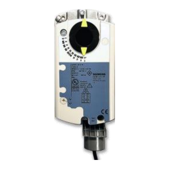
OpenAir® Electronic Damper Actuators
GDE Series
Enhanced Non-spring Return Rotary
Description
The OpenAir direct coupled enhanced non-spring return rotary electric actuators are
designed for two-position/floating or modulating control of dampers.
Features
Application
These actuators are used in constant or variable air volume installations for control of
HVAC dampers requiring up to 44 lb-in (5 Nm) of torque.
Product Numbers
Torque
Product Number
GDE141.1U
GDE141.1U/B (24 pk)
GDE141.1P
GDE141.1P/B (24 pk)
GDE141.1Q
GDE142.1P*
GDE146.1P*
44 lb-in
GDE341.1U
(5 Nm)
GDE346.1U*
GDE161.1P
GDE161.1P/B (24 pk)
GDE161.1Q
GDE163.1P
GDE164.1P*
GDE166.1P*
* For conduit adaption, order an ASK76.1U Conduit Adapter. See Accessories.
Selectable modulating control signal (0 to 10 Vdc or 2 to 10 Vdc).
24 Vac/dc compatible.
New line voltage (34x models) for 100 to 240 Vac two-position/floating control.
Integral 1/2-inch conduit connection.
Manual override.
Independently adjustable dual auxiliary switches available.
cUL and UL listed;
certified
Control
Signal
2-position/
Floating
Modulating
0(2) to 10 Vdc
Technical Instructions
Document No. 155-784
Table 1.
Dual
Feedback
Auxiliary
Switches
—
—
—
—
—
—
—
—
—
—
•
—
—
•
—
—
•
•
•
—
•
—
•
—
•
—
•
•
•
•
October 20, 2016
Pre-Cabled Power Supply
Standard
Standard
Plenum
Plenum
24 Vac/dc
6-ft length
Plenum
Plenum
Standard
100 to 240 Vac
Standard
Plenum
24 Vac/dc
Plenum
6-ft length
Plenum
Plenum
Plenum
Siemens Industry, Inc.
Advertisement
Table of Contents

Related Manuals for Siemens OpenAir GDE141.1U


Summary of Contents for Siemens OpenAir GDE141.1U
- Page 1 GDE161.1P/B (24 pk) Plenum • — GDE161.1Q 6-ft length Modulating • — GDE163.1P Plenum 0(2) to 10 Vdc • • GDE164.1P* Plenum • • GDE166.1P* Plenum * For conduit adaption, order an ASK76.1U Conduit Adapter. See Accessories. Siemens Industry, Inc.
-
Page 2: Specifications
Runtime for 90° opening or closing 90 sec. at 60 Hz (125 sec. at 50 Hz) Nominal angle of rotation 90° Maximum angular rotation 95° Shaft size: Minimum shaft length 3/4-inch (20 mm) Mounting Figure 1. Acceptable Shaft Sizes. Page 2 Siemens Industry, Inc. - Page 3 All other standard actuator models have built-in conduit adapters. Figure 2. Conduit Adapter. ASK71.5: Allows a direct-coupled actuator to provide an auxiliary linear drive. Figure 3. Rotary-to-Linear. Siemens Industry, Inc. Page 3...
- Page 4 ASK75.7U Weather Shield and outdoor- rated conduit fittings. This weather shield may be mounted in any orientation. Figure 7. NEMA Type 4X Weather Shield. For dimensions, see Figure 30. Page 4 Siemens Industry, Inc.
-
Page 5: Actuator Components
10. Auxiliary Switch B 11. Position indicator 12. Adjustment lever with locking screw (4 mm hex) 13. Set screw for mechanical range stop (4 mm hex) 14. Mounting bracket Figure 8. Parts of the Actuator. Siemens Industry, Inc. Page 5... -
Page 6: Operation
The Y input is limited to a maximum of 10 Vdc. If the sum of the offset and slope setting is greater than 10V, the angle of rotation is reduced providing the feature of electronic limitation of the angle of rotation. Page 6 Siemens Industry, Inc. - Page 7 Settings: Uo = 2 Vdc; U = 16 Vdc Electronic limitation angle of rotation Ys = 50% (45°) U = 16V Slope Active voltage range Uw = 2 to 10 Vdc Figure 12. Example. Siemens Industry, Inc. Page 7...
- Page 8 ) to point to the position of Switch A. Use AUX SWITCH ADJUSTMENT the narrower tab on the red ring to point to the position of Switch B. Rotation Direction GDE14x.1P, GDE34x.1U Two-position/Floating Control Figure 14. Setting the Rotation Direction. Page 8 Siemens Industry, Inc.
- Page 9 0 to10 Vdc or a 2 to 10 Vdc signal, within the adjusted mechanical range. The feedback signal will also reflect the control signal selected, either a 0 to 10 Vdc or a 2 to 10 Vdc. Siemens Industry, Inc. Page 9...
-
Page 10: Mounting And Installation
Use the shaft insert supplied for any Guide 3/8-inch (8 to 10mm) diameter shaft Figure 18. Damper Shaft Sizes. NOTE: For all damper shafts with the exception of the 1/2-inch round shaft: Remove 1/2-inch Ø factory-installed guide before installation. Page 10 Siemens Industry, Inc. - Page 11 All six outputs of the dual auxiliary switch (A and B) must only be connected to: Class 2 voltage (UL/CSA). Separated Extra-Low Voltage (SELV) or Protective Extra Low Voltage (PELV) (according to HD384-4-41) for installations requiring conformance. Siemens Industry, Inc. Page 11...
- Page 12 Feedback Potentiometer Black Common Feedback Potentiometer Black 100 to 0% P3 - P2 (5,000 to 0 ohms) Figure 22. 2-Position, SPST (Single-Pole, Single-Throw). Figure 23. 2-Position, SPDT Figure 24. Floating Control (Single-Pole, Double-Throw). 24 Vac/dc. Page 12 Siemens Industry, Inc.
- Page 13 Factory-installed Options Switch A Common Gray/Red Switch A - NC Gray/Blue Switch A - NO Gray/Pink Switch B - Common Black/Red Figure 29. GDE16x Wiring Diagram. Switch B - NC Black/Blue Switch B - NO Black/Pink Siemens Industry, Inc. Page 13...
- Page 14 Connect wires S4 and S5 to the DMM. The DMM should indicate an open circuit or no resistance. Apply a control signal to wires 1 (red) and 7 (orange). The DMM should indicate contact closure as the actuator shaft coupling reaches the setting of Switch B. Page 14 Siemens Industry, Inc.
- Page 15 Connect wires S4 and S5 to the DMM. The DMM should indicate open circuit or no resistance. Apply a control signal (100 to 240 Vac) to wires 4 (light blue) and 7 (white) The DMM should indicate contact closure as the actuator shaft coupling reaches the setting of Switch B. Siemens Industry, Inc. Page 15...
-
Page 16: Troubleshooting
Stop the signal to wire 8 (gray). The DMM should indicate contact closure as the actuator shaft coupling reaches the setting of Switch B. Troubleshooting WARNING: Do not open the actuator. If the actuator is inoperative, replace the unit. Page 16 Siemens Industry, Inc. - Page 17 Information in this publication is based on current specifications. The company reserves the right to make changes in specifications and models as design improvements are introduced. OpenAir is a registered trademark of Siemens Industry, Inc. Other product or company names mentioned herein may be the trademarks of their respective owners.