
Related Manuals for Omega SP-003


Summary of Contents for Omega SP-003
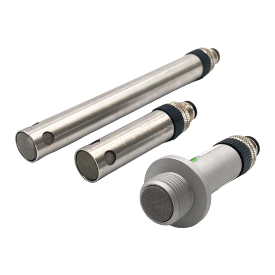
- Page 1 User’ s Gui d e 5” Tube Housing 3” Tube Housing 3” Bulkhead Housing SP-003 / SP-004 Omega Link Environmental Monitoring Smart Probe...
- Page 2 Fax: (203) 359-7700 e-mail: info@omega.com The information contained in this document is believed to be correct, but OMEGA accepts no liability for any errors it contains and reserves the right to alter specifications without notice. M 5 7 4 8...
-
Page 3: Table Of Contents
Communication Interface ........................... 10 Input Configuration ............................12 Temperature, Humidity, and Barometric Pressure (SP-003 Only) ..............12 Dewpoint, Humidex, and Heat Index Sensor (SP-003-2 and SP-004-2 only) ..............12 Temperature and Humidity Interface (SP-004 Only) ..................12 Discrete Input/Output (DIO) ..........................13 Setting DIO as an Input .............................. - Page 4 Humidity Data Type/Format ............................23 Humidity Configuration Byte ............................23 Humidity Device Byte ............................24 Humidity Parameters ............................24 Humidity User Calibration ........................... 24 IPSO Relative Humidity Definition ........................24 Precision ................................... 24 Sensor Trigger Function..............................24 Barometric Pressure Interface ........................25 Barometric Pressure Descriptor ..........................
- Page 5 SERVO Rate .................................. 36 Output Type ................................ 36 Active State ................................. 36 Mapping Enabled ..............................36 Sensor Mapping ..............................36 M 5 7 4 8...
-
Page 6: Notes, Cautions And Warnings
The following labels identify information that is especially important to note: Note: Provides you with information that is important to successfully setup and use the Omega Link device. Caution or Warning: Tells you about the risk of electrical shock. -
Page 7: Introduction
The SP-003/SP-004 accepts Omega Link Smart Interfaces through its M12 8-pin connector. The Omega Link SP-003/SP-004 features 2 configurable digital I/O pins. These can be used for a myriad of applications including driving relays, physical alarms, or sensing dry contacts like door switches. The SP-003/SP-004 can also be utilized as an edge controller with autonomous independent decision-making capabilities to generate local alarms or provide control outputs based on sensor inputs. -
Page 8: Specifications
Dimensions: 73 mm L x 15.9 mm OD x 18.5 mm Panel Opening (2.83” x 0.62” x 0.72”) GENERAL Agency Approvals: CE, UKCA Configuration: Configurable via Omega Link Smart Interface and SYNC configuration software Software: Compatible with OEG, SYNC, and OMEGA Cloud M 5 7 4 8... -
Page 9: Hardware Setup
Connecting to your Omega Link Smart Interface The SP-003/SP-004 requires an Omega Link Smart Interface to connect to a computer. OMEGA offers a variety of Smart Interfaces such as the wired IF-001 or wireless IF-006. Use the M12 8-Pin Connector diagram below to connect your SP-003/SP-004 to your Omega Link Smart Interface. -
Page 10: Sync Configuration
SYNC Configuration Omega Link Smart Probe products are easily configured through Omega’s free SYNC configuration software. Ensure SYNC is running on a Windows OS computer before continuing. Connect the SP-003/SP-004 to the computer using your Omega Link Smart Interface to begin. - Page 11 • Device Address: If your Smart Interface is part of a network, enter the Network Address here. The default network address is 1 for most devices. Please refer to the manual of your Smart Interface for more information. Note: The default Device Address is 1. •...
-
Page 12: Input Configuration
Input Configuration The SP-003 provides input readings for Temperature, Humidity, and Barometric Pressure with the SP-003-2 and SP- 004-2 also offering Dewpoint, Humidex, and Heat Index readings. Temperature, Humidity, and Barometric Pressure (SP-003 Only) To configure these inputs, click the Inputs configuration tab on SYNC and choose your preferred input sensor mix from the Type dropdown. -
Page 13: Discrete Input/Output (Dio)
Discrete Input/Output (DIO) The Omega Link SP-003/SP-004 features 2 configurable discrete I/O pins. These can be used for a myriad of applications including driving relays, physical alarms, or sensing dry contacts like door switches. The user may configure the polarity of the inputs (active HIGH or active LOW) or Disable the DIO to utilize the outputs (ON/OFF, PWM, SERVO). -
Page 14: Setting Dio As An Input
Figure 17: SYNC interface Digital_IO Advanced Scaling Options The Omega Link SP-003/SP-004 allows for advanced scaling options on process and pulse inputs only. The Advanced Scaling checkbox can be selected to expand additional configuration options. A gain and/or offset can be applied to the input reading and the displayed unit can be changed. -
Page 15: Output Configuration
Output Configuration The SP-003/SP-004 offers two discrete outputs that share circuitry with the discrete inputs. If an output is to be used then the corresponding input pin must be set to Disable. See section 5.3.1 Discrete Input/Output (DIO) for more information. -
Page 16: Device Output Range/Types
Device Output Range/Types There are three types of output options – On/Off, Pulse-Width Modulation (PWM), or Servo. This section describes these output options. Figure 19: SYNC interface output type selection ON/OFF Output Type The ON/OFF output mode switches the output to be a binary ON or OFF. Depending on if the output is configured as Active Low or Active High, the ON/OFF mode can correspond to different polarities. -
Page 17: On/Off Control Module
Example: For the percent of angular travel, if the pulse width range is set to a range of 1.0-2.0 msec, then selecting 50% of angular travel represents 1.5 msec or 90 degrees of travel. 50 Hz 100% Angular Travel = 2.0 msec 1.0 msec = 0°... -
Page 18: Setting An Alarm
The DeadBand field together with the direct or reverse control action configures a deadband range around the Setpoint where the ON/OFF control does not toggle. The unit of the DeadBand field will be the same as the unit of the chosen Input. •... -
Page 19: Pairing A Sensing Device To An Omega Link Gateway
Pairing a Sensing Device to an Omega Link Gateway Refer to either the Wired or Wireless instructions to pair an Omega Link Smart Probe & Interface to an Omega Link Gateway. Before continuing to the pairing instructions, ensure the following prerequisites are met: •... -
Page 20: Appendix: Sp-003/Sp-004 Registers
These registers may be accessed using I2C based commands directly to the Smart Probe devices or through a set of Modbus based registers when using Omega Interface devices. Refer to the Smart Sensor Device Interface manual for further information. -
Page 21: Temperature Sensor
Data Type The 4-bit Data Type field determines the type of data of the specific senso. Factory Calibrate Factory calibration is available for the SP-003 process inputs. Clearing this bit will disable the factory calibration values. Writeable The writeable bit is cleared, indicating that the sensor values may not be overwritten. -
Page 22: Temperature Device Byte
Lock If set, the user specified units of measure string (4 character maximum) will be used in place of the default units of measure. Apply Scaling If set, the user defined Offset and Gain values will be used to adjust the sensor reading: Result = (Raw Reading * Gain) + Offset Assigned The Assigned bit will always read as 0. -
Page 23: Humidity Sensor Interface
Humidity Sensor Interface The Humidity sensor provides readings of 0 to 100 % Relative Humidity. Humidity Descriptor Offset Name Value Description 0x00 Sensor Type 0x02 Relative humidity (%) 0x01 Data Type/Format 0x06 Float type 0x02 Configuration See below 0x03 Sensor Device 0x00 Not Used 0x04... -
Page 24: Humidity Device Byte
Apply Scaling If set, the user defined Offset and Gain values will be used to adjust the sensor reading: Result = (Raw Reading * Gain) + Offset Assigned The Assigned bit will always read as 0. Available The Available bit will always read as 0. Humidity Device Byte The Humidity Device Byte is not used. -
Page 25: Barometric Pressure Interface
Barometric Pressure Interface The Barometric pressure sensor provides readings in the range of 300 to 1100 mbar. Barometric Pressure Descriptor Offset Name Value Description 0x00 Sensor Type 0x03 Barometric Pressure in mbar 0x01 Data Type/Format 0x06 Float type 0x02 Configuration See below 0x03 Sensor Device... -
Page 26: Barometric Pressure Device Byte
Apply Scaling If set, the user defined Offset and Gain values will be used to adjust the sensor reading: Result = (Raw Reading * Gain) + Offset Assigned The Assigned bit will always read as 0. Available The Available bit will always read as 0. Barometric Pressure Device Byte The Barometric Pressure Device Byte is not used. -
Page 27: Dewpoint Interface
Dewpoint Interface The Dewpoint sensor available on the SP-003-2 and SP-004-2 provides the calculated dewpoint based on the measured temperature and relative humidity. Dewpoint Descriptor Offset Name Value Description 0x00 Sensor Type 0x36 Dewpoint temperature in oC 0x01 Data Type/Format... -
Page 28: Dewpoint Temperature Device Byte
Apply Scaling If set, the user defined Offset and Gain values will be used to adjust the sensor reading: Result = (Raw Reading * Gain) + Offset Assigned The Assigned bit will always read as 0. Available The Available bit will always read as 0. Dewpoint Temperature Device Byte The Dewpoint Temperature Device Byte is not used. -
Page 29: Apparent Heat Interface
Apparent Heat Interface The Apparent Heat sensor provides a Heat Index (US) or Humidex (CAN) calculated value on the SP-003-2 and SP-004- 2. These calculations are based on the measured temperature and relative humidity and the calculated Dewpoint value. Apparent Heat Descriptor... -
Page 30: Apparent Heat Configuration Byte
Apparent Heat Configuration Byte Apparent Temperature Configuration Byte Apply Available Assigned Lock Sensor Selection Scaling Heat Index Humidex <reserved> 2..15 Lock If set, the user specified units of measure string (4 character maximum) will be used in place of the default units of measure. Apply Scaling If set, the user defined Offset and Gain values will be used to adjust the sensor reading: Result = (Raw Reading * Gain) + Offset... -
Page 31: Digital Input/Output (Dio) Interface
Digital Input/Output (DIO) Interface The SP-003/SP-004 supports a Digital Input/Output Interface that provides 2 digital inputs which are hardwired to the Digital outputs. The DIO inputs may be used to detect the state of external switches (output off) or to monitor the state of the outputs. -
Page 32: Dio Input Configuration
Factory Calibrate The Factory Calibrate bit is not used for DIO types. Writeable Indicates that the sensor value may be overwritten. Not used on DIO inputs. Smart Sensor The bit is cleared. DIO Input Configuration DIO Input Configuration Apply Available Assigned Lock Sub Channel Selection... -
Page 33: Dio Ipso Definition
DIO IPSO Definition The DIO input IPSO definition provides signal range, measured min/max values, IPSO object type information. Offset Name Value Description 0x00 Sensor Type 3349 Bit Mapped Digital 0x02 Precision Provides reading of xxx 0x04 Reset Min/Max Write 0x0001 force reset of min / max 0x08 Min Measured Minimum reading since last reset... -
Page 34: Scaling Minimum / Maximum Values
Scaling Minimum / Maximum Values When Input Mapping is used the user may specify the input signal range through the Input Minimum and Input Maximum parameters. There is one pair of registers for each of the 4 possible outputs. Modbus Sensor Name Size... -
Page 35: Digital Output Configuration
Rate The Rate determines the repetition rate, or frequency, of the Digital Output. For On/Off outputs the rate field is ignored. PWM Rate The SP-003/SP-004 supports the following PWM frequencies: PWM Rate Name Description PWM signal has constant 100 Hertz frequency (10 msec repetition 100 Hz rate) with 0 –... - Page 36 SERVO Rate Smart Sensor probes support the following SERVO frequencies: PWM Rate Name Description PWM signal has constant 100 Hertz frequency (10 100 Hz msec repetition rate) with 0 – 100 % duty cycle PWM signal has constant 50 Hertz frequency (20 50 Hz msec repetition rate) with 0 –...
- Page 37 Department will issue an Authorized Return (AR) number immediately upon phone or written request. Upon examination by OMEGA, if the unit is found to be defective, it will be repaired or replaced at no charge. OMEGA’s WARRANTY does not apply to defects resulting from any action of the purchaser, including but not limited to mishandling, improper interfacing, operation outside of design limits, improper repair, or unauthorized modification.
- Page 38 Where Do I Find Everything I Need for Process Measurement and Control? OMEGA…Of Course! Shop online at omega.com TEMPERATURE M U Thermocouple, RTD & Thermistor Probes, Connectors, Panels & Assemblies M U Wire: Thermocouple, RTD & Thermistor M U Calibrators & Ice Point References M U Recorders, Controllers &...