Table of Contents
Advertisement
Quick Links
COMMERCIAL ELECTRIC WATER HEATER
500 Tennessee Waltz Parkway
Ashland City, TN 37015
Thank you for buying this energy efficient water heater.
We appreciate your confidence in our products.
Read and understand this instruction
manual and the safety messages
herein before installing, operating or
servicing this water heater.
Failure to follow these instructions and
safety messages could result in death
or serious injury.
This manual must remain with the
water heater.
PLACE THESE INSTRUCTIONS ADJACENT TO HEATER AND NOTIFY OWNER TO KEEP FOR FUTURE REFERENCE.
PRINTED 1215
LOW LEAD
CONTENT
Instruction Manual
MODELS SEV-150 THRU SEV-10000
SEH-200 THRU SEH-10000
INSTALLATION - OPERATION - SERVICE
MAINTENANCE - LIMITED WARRANTY
If the heater becomes immersed in water up to or
above the level of the bottom of the element doors,
the heater should be examined by a qualified service
agency before it is placed in operation, see Page 2.
329762-001
Advertisement
Table of Contents

Related Manuals for State Water Heaters SEH-250


Summary of Contents for State Water Heaters SEH-250
- Page 1 Instruction Manual COMMERCIAL ELECTRIC WATER HEATER MODELS SEV-150 THRU SEV-10000 SEH-200 THRU SEH-10000 INSTALLATION - OPERATION - SERVICE MAINTENANCE - LIMITED WARRANTY 500 Tennessee Waltz Parkway Ashland City, TN 37015 LOW LEAD CONTENT Thank you for buying this energy efficient water heater. We appreciate your confidence in our products.
-
Page 2: Table Of Contents
TABLE OF CONTENTS This manual contains the operating instructions for the commercial electric Xi control. It is intended to be used in conjunction with the water heater instruction manual. TABLE OF CONTENTS ............2 Closed Water Systems ..........13 SAFE INSTALLATION, USE AND SERVICE ......3 Thermal Expansion ............ -
Page 3: Safe Installation, Use And Service
SAFE INSTALLATION, USE AND SERVICE The proper installation, use and servicing of this water heater is extremely important to your safety and the safety of others. Many safety-related messages and instructions have been provided in this manual and on your own water heater to warn you and others of a potential injury hazard. -
Page 4: General Safety Information
GENERAL SAFETY INFORMATION PRECAUTIONS HYDROGEN GAS (FLAMMABLE) DO NOT USE THIS APPLIANCE IF ANY PART HAS BEEN EXPOSED TO FLOODING OR WATER DAMAGE. Immediately call a qualified service technician to inspect the appliance and to replace any part of the control system which has been under water. Explosion Hazard If the unit is exposed to the following, do not operate heater until all corrective steps have been made by a qualified service technician. -
Page 5: General Safety Information
GENERAL SAFETY INFORMATION When servicing this unit, verify the power to the unit is turned off prior to opening the control cabinet door. Read and understand this instruction Before removing any access manual and the safety messages panels or servicing the water herein before installing, operating or heater, make sure the electrical servicing this water heater. supply to the water heater is Failure to follow these instructions and turned “OFF”. -
Page 6: Approvals
APPROVALS LOW LEAD CONTENT All models are listed by Underwriters Laboratories Inc. MODEL AND RATING... -
Page 7: Introduction
INTRODUCTION Thank You for purchasing this water heater. Properly installed Be sure to turn off power when working on or near electrical system of the water heater. Never touch electrical and maintained, it should give you years of trouble free service. components with wet hands or when standing in water. -
Page 8: Dimensions And Capacities Data
Depth Spacing Opening Outlet Drain Valve Model* Capacity KW Input Opening Opening Opening** HORIZONTAL ELECTRIC STORAGE HEATER SEH-200 38-1/2 10-1/2 17-1/2 1-1/2 SEH-250 38-1/2 10-1/2 1-1/2 SEH-300 44-1/2 8-1/4 Optional SEH-350 44-1/2 8-1/4 SEH-400 44-1/2 8-1/4 26-1/2 27-1/2 SEH-500 1-1/4 4″... -
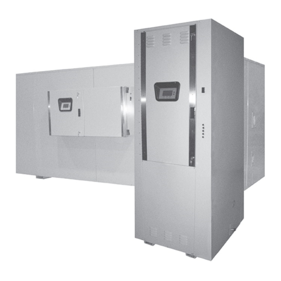
Page 9: Features And Components
FEATURES AND COMPONENTS NOTE: Your actual configuration may vary. Vertical Water Heater (typical). -
Page 10: Features And Components
FEATURES AND COMPONENTS NOTE: Your actual configuration may vary. Horizontal Water Heater (typical). -
Page 11: Locating The New Water Heater
LOCATING THE NEW WATER HEATER FACTS TO CONSIDER ABOUT THE LOCATION dimensions of the water heater and should be piped to an adequate drain. CAUTION The discharge opening of the relief valve should always be piped to an open drain. Property Damage Hazard 3. -
Page 12: Circulating Pump
refrigerants, swimming pool chemicals, water softener chemicals, For safe operation of the water heater, the temperature and pressure calcium and sodium chloride, waxes, and process chemicals are relief valve must not be removed from its designated opening nor typical compounds which are potentially corrosive. These materials plugged. -
Page 13: Closed Water Systems
CLOSED WATER SYSTEMS cause premature tank failure (leakage). This type of failure is not covered under the limited warranty. Thermal expansion can also Water supply systems may, because of code requirements or such cause intermittent temperature-pressure relief valve operation: conditions as high line pressure, among others, have installed water discharged from the valve due to excessive pressure build devices such as pressure reducing valves, check valves, and back up. -
Page 14: Electrical And Recoveries Data
CONTROL CIRCUITS Additional instructional literature is provided with heaters equipped with modulating solid state step control or a sequencer. The heater is equipped with one of the following control circuits, All control circuits are operated on single-phase 120 volt current. resulting in: Control circuit wiring is 14 Awg, AWM (Appliance Wiring Material) A. -
Page 15: Wiring Diagrams
WIRING DIAGRAMS WIRING DIAGRAMS DIAGRAM 1. LARGE COMMERCIAL WIRE DIAGRAM 208-240V / 3PH W/O SLAVES DIAGRAM 2. LARGE COMMERCIAL WIRE DIAGRAM 300-600V/3PH W/O SLAVES... -
Page 18: Operation
OPERATION WIRING DIAGRAMS GENERAL 7. Close the cabinet door and perform start up checks listed below before turning on the electricity. Refer to the Features and Components section of this manual (pages 9 & 10) for the location of components mentioned in the INITIAL START UP instructions that follow. -
Page 19: Temperature Regulation
TEMPERATURE REGULATION HIGH TEMPERATURE LIMIT CONTROLS (ECO) TEMPERATURE ADJUSTMENT If a HWL L4008A series high limit is used in place of the ECO in DANGER the probe it (HWL L4008A) should not be set above 190°F/88°C. When the ECO switch contacts open (activate) the electronic Full power is present whenever the control system locks out and displays a Fault message. -
Page 20: Control System Operation
CONTROL SYSTEM OPERATION HEATING ELEMENT OPERATION appears on the LCD screen above an Operational Button there is no function assigned. Progressive Sequencing: Elements are energized and de-energized THE DESKTOP SCREEN according to adjustable (1 to 20°F) Differential set points for each element. Element Rotation - first element on is rotated with each successive call for heat. - Page 21 TABLE 1 - STATUS ICONS ICON DESCRIPTION Water temperature in the tank has fallen. Shaded area of the animated thermometer icon will rise and fall in response to water temperature in the storage tank as sensed from the immersion Temperature Probe. Water temperature in the tank has reached the Operating Set Point.
- Page 22 TABLE 3 - CONTROL SYSTEM MENUS MENUS DESCRIPTION Most commonly accessed menu. Operating Set Point, Differential settings, Tank Temperature and Tank Probe Temperatures Offset are located in this menu. Current Operating State/Mode (heating/standby etc) and status (open/closed - on/off - yes/no) of monitored Heater Status water heater functions and components are displayed in this menu.
- Page 23 TEMPERATURES MENU Operating Sequence On a water heater equipped with 3 heating elements, with an Operating Set Point Operating Set Point of 120°F and all Differential settings at 2°F the On/Off sequencing of heating elements would be as follows: User adjustable setting 90°F to 190°F range; factory default is 120°F.
- Page 24 Temperature Settings The Operating Set Point and the Differential Settings are adjusted in the Temperatures Menu. The following instructions explain how to adjust these user settings and navigate the control system menus. ACTION DISPLAY From the Desktop Screen, press the Operational Button underneath “MENU”...
- Page 25 WATER HEATER STATUS MENU Element # On Displays the on/off status of each heating element. Yes = On, No = This menu displays non adjustable operational information. Use the Off. Up & Down Buttons to navigate to the bottom of this menu. Tank Full Top of Menu Displays the status of the optional LWCO (Low Water Cut Off) device.
- Page 26 The Economy Set Point is the water temperature the control Daily Operating Mode (Sun - Mon - Tue - Wed - Thu - Fri - Sat) system maintains during programmed Economy Mode time periods. “Economy Set Point” is displayed instead of Seven daily sub menus are listed at the bottom of the Economy “Operating Set Point” and “Economy Mode” appears beneath Mode Setup menu.
- Page 27 ECONOMY MODE SETTINGS Setpoint Adjustment Value ACTION DISPLAY From the Desktop screen, press the Operational Button underneath “MENU” to enter the Main Menu. Notice how the text above the Operational Buttons on the display changes as you navigate through the various menus and screens. Use the Up/Down buttons to select (highlight in black) the Economy Mode Setup menu from the Main Menu.
- Page 28 ECONOMY MODE SETTINGS Time Clock Settings ACTION DISPLAY From the Desktop Screen navigate to the Economy Mode Setup menu. Use the Up/Down buttons to select (highlight in black) Current Time sub menu. Press the Operational Button underneath “CHANGE” to enter the Current Time sub menu.
- Page 29 ECONOMY MODE SETTINGS Daily Operating Mode Settings ACTION DISPLAY Economy Mode All Day: From the Economy Mode Setup menu use the Up/Down buttons to select (highlight in black) the Daily sub menu for “Sun.” Press the Operational Button underneath “CHANGE” to enter this menu. Use the Up/Down buttons to select (highlight in black) the “Economy Mode All Day”...
- Page 30 ALARM OUTPUT SETUP MENU Alarm Output Settings Changing the user settings in this menu is done using the same Permits user to set the condition (from a list of options) for when methods for changing the Operating Set Point. the CCB’s integral alarm output relay will be energized. Alarm relay connections (common, normally open, normally closed) are located on Service Note: Adjustable user settings in the Alarm Output Setup the J3 terminal strip on the CCB - see wiring diagrams.
- Page 31 Bottom of Menu messages in chronological order in this menu. The most recent will be at the top of the list. A time stamp is displayed below each listed Fault and Alert message showing when the Fault or Alert condition occurred. The Fault History is useful when dealing with intermittent operational problems or when the customer has reset the control system prior to a service agent’s arrival.
-
Page 32: Maintenance
RESTORE FACTORY DEFAULTS MENU This control system menu allows the user to restore most of the control system’s user settings to their factory default settings. User settings in the Alarm Output Setup and Display Settings menus are unaffected by executing Restore Factory Defaults. Restore Factory Defaults ACTION DISPLAY From the Main Menu use the Up/Down buttons to select (highlight in black) the “Restore Factory Defaults”... - Page 33 ANODE ROD INSPECTION FLUSHING THE WATER HEATER 1. Turn off the electrical supply to the water heater at the CAUTION breaker or disconnect switch. 2. Ensure the cold water inlet valve is open. Property Damage Hazard 3. Open a nearby hot water faucet and let the water run until •...
- Page 34 THE PROCESS FOR LIME SCALE REMOVAL IS AS FOLLOWS: OTHER SCALE REMOVAL: 1. Turn off electrical disconnect switch. 1. Flush cleaned ends of elements with water when deliming or cleaning is completed. 2. Drain the heater following DRAINING instructions. 2. Remove sediment and scale from the tank bottom through the 3.
-
Page 35: Troubleshooting Checklist
TROUBLESHOOTING CHECKLIST CHECKLIST WATER HEATER MAKES STRANGE SOUNDS Before calling for service, check the following points to see if the Sediment or lime scale accumulations on the elements causes cause of trouble can be identified and corrected. Reviewing this sizzling and hissing noises when the heater is operating. checklist may eliminate the need of a service call and quickly restore The sounds are normal, however, the tank bottom and elements hot water service. -
Page 36: Warranty
For your records, fill in the product: Serial: ___________________ Model: ___________________ U.S. Customers: State Water Heaters 500 Tennessee Waltz Parkway Ashland City, Tennessee 37015 800-365-0024 www.statewaterheaters.com... -
Page 37: Notes
NOTES... - Page 38 NOTES...
- Page 39 NOTES...
- Page 40 500 Tennessee Waltz Parkway, Ashland City, TN 37015 Technical Support: 800-365-8170 • Parts: 800-821-2017 www.statewaterheaters.com Copyright © 2014 State Industries, Inc., All rights reserved.