Advertisement
Quick Links
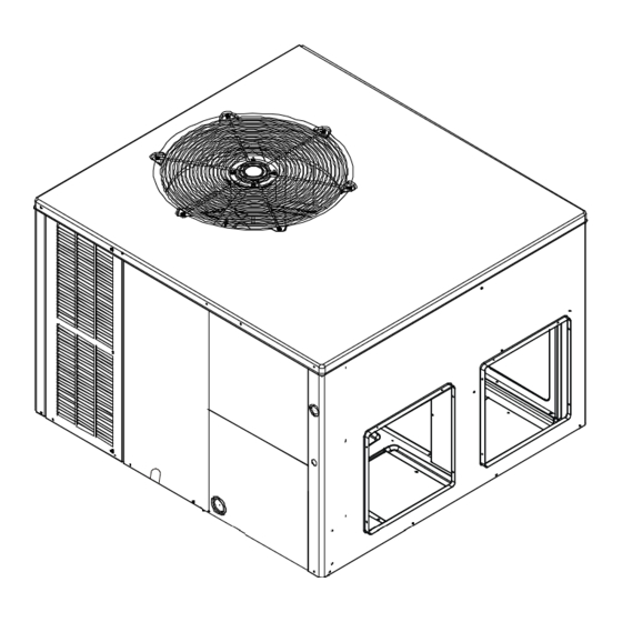
Installation Instructions for Self-Contained Package
Heat Pump Units DP5HM 15.2 SEER2 "M" SERIES 2-4 Ton
Affix this manual and Users Information Manual
adjacent to the unit.
Do not bypass safety devices.
Our continuing commitment to quality products may mean a change in specifications without notice.
© 2022
IOD-3030A
10/2022
WARNING
19001 Kermier Rd. Waller, TX 77484
www.daikincomfort.com
INSTALLATION INSTRUCTIONS
ONLY PERSONNEL THAT HAVE BEEN TRAINED TO
INSTALL, ADJUST, SERVICE, MAINTENANCE OR REPAIR
(HEREINAFTER, "SERVICE") THE EQUIPMENT SPECIFIED
IN THIS MANUAL SHOULD SERVICE THE EQUIPMENT. THE
MANUFACTURER WILL NOT BE RESPONSIBLE FOR ANY
INJURY OR PROPERTY DAMAGE ARISING FROM IMPROPER
SERVICE OR SERVICE PROCEDURES. IF YOU SERVICE THIS
UNIT, YOU ASSUME RESPONSIBILITY FOR ANY INJURY OR
PROPERTY DAMAGE WHICH MAY RESULT. IN ADDITION, IN
JURISDICTIONS THAT REQUIRE ONE OR MORE LICENSES
TO SERVICE THE EQUIPMENT SPECIFIED IN THIS MANUAL,
ONLY LICENSED PERSONNEL SHOULD SERVICE THE
EQUIPMENT. IMPROPER INSTALLATION, ADJUSTMENT,
SERVICING, MAINTENANCE OR REPAIR OF THE EQUIPMENT
SPECIFIED IN THIS MANUAL, OR ATTEMPTING TO INSTALL,
ADJUST, SERVICE OR REPAIR THE EQUIPMENT SPECIFIED
IN THIS MANUAL WITHOUT PROPER TRAINING MAY RESULT
IN PRODUCT DAMAGE, PROPERTY DAMAGE, PERSONAL
INJURY OR DEATH.
ATTENTION INSTALLING PERSONNEL:
Prior to installation, thoroughly familiarize yourself with this
Installation Manual. Observe all safety warnings. During
installation or repair, caution is to be observed.
It is your responsibility to install the product safely and to
educate the customer on its safe use.
RECOGNIZE THIS SYMBOL
AS A SAFETY PRECAUTION.
These installation instructions cover the outdoor
installation of self contained package air conditioners and
heating units. See the Specification Sheets applicable to
your model for information regarding accessories.
*NOTE: Please contact your distributor or our website
for the applicable Specification Sheets referred to in this
manual.
WARNING
Advertisement

Related Manuals for Daikin DP5HM


Summary of Contents for Daikin DP5HM
- Page 1 INSTALLATION INSTRUCTIONS Installation Instructions for Self-Contained Package Heat Pump Units DP5HM 15.2 SEER2 “M” SERIES 2-4 Ton WARNING ONLY PERSONNEL THAT HAVE BEEN TRAINED TO INSTALL, ADJUST, SERVICE, MAINTENANCE OR REPAIR (HEREINAFTER, “SERVICE”) THE EQUIPMENT SPECIFIED IN THIS MANUAL SHOULD SERVICE THE EQUIPMENT. THE...
- Page 2 Rigging Details ............5 TROUBLESHOOTING CHART ........17 CIRCULATING AIR AND FILTERS.........6 DP5HM BLOWER PERFORMANCE DATA ....18 Air flow Conversion ..........6 DP5HM CFM OUTPUT AND DIP SWITCH SETTINGS ...19 Duct work ..............6 DIMENSIONS ..............20 Manufactured Home MOD Kit ........6 HOWEOWNER’S ROUTINE MAINTENANCE .....21 Plenum Application .............7...
- Page 3 885-770-5678 CODES AND REGULATIONS IMPORTANT SAFETY INSTRUCTIONS General The DP5HM SEER2 M-Series heat pumps are designed Recognize Safety Symbols, Words, and Labels for OUTDOOR USE ONLY. The DP5HM SEER2 M-Series The following symbols and labels are used throughout this is available in cooling capacities of 2, 2.5 3, 3.5 and 4 manual to indicate immediate or potential safety hazards.
- Page 4 Specification sheets can be found at Clearances and Accessibility www.daikincomfort.com for Daikin brand products. Within The unit is designed to be located outside the building with the website, please select the residential or commercial unobstructed condenser air inlet and discharge. Additionally,...
- Page 5 Heat pumps require special location consideration in areas Curbing must be installed in compliance with the National of heavy snow accumulation and/or areas with prolonged Roofing Contractors Association Manual. Construct duct continuous subfreezing temperatures. Heat pump unit work using current industry guidelines. The duct work must bases have holes under the outdoor coil to permit drainage be placed into the roof curb before mounting the package of defrost water accumulation.
- Page 6 Horizontal Air Flow CAUTION Single phase models are shipped without horizontal duct covers. If needed, these kits may be ordered through Daikin’s Service Parts department. To avoid possible personal injury, a safe, flat surface for service personnel should be provided. WARNING To prevent possible equipment damage, property damage, personal injury or death.
- Page 7 to supply and return outlets. Use of non-flammable It is strongly encouraged to use appropriately sized ducts weatherproof flexible connectors on both supply and return based upon the CFM for your application (unit’s CFM). If connections at the unit to reduce noise transmission is duct sizing through industry manuals or air duct calculators recommended.
- Page 8 NOTE: DP5HM units have two-stage heating/cooling and require thermostats with two-stage heat/cool The units are designed for operation at the voltage, and optional auxiliary heat control.
- Page 9 2. Inspect all registers and set them to the normal open DP5HM[24-48] position. Terminal Thermostat 3. Turn on the electrical supply at the disconnect. R (24V) 4. Turn the fan switch to the “ON” position. The blower should begin ramping up immediately.
- Page 10 NOTE: 15.2 SEER2 models have two stages of thermostat closes at 67° and opens at 85°. It warms compressor heat. During resistance heat test, the compressor crankcase thereby preventing liquid increase temperature setting until third stage heat is migration and subsequent compressor damage. The energized.
- Page 11 Some room thermostats do not energize the motor TYPICAL HEAT PUMP SYSTEM IN HEATING during electric heat. This relay ensures blower operation when the room thermostat energizes heat. This relay is energized by the electric heat kit sequencer. Reversing Valve (De-Energized) HEAT PUMP OPERATION Indoor...
- Page 12 Defrost Control NOTE: Remove jumper across defrost thermostat During operation the power to the circuit board is controlled before returning system to service. See figure 11 - by a temperature sensor, which is clamped to a return bend Defrost Control Wiring Diagram. entering the outdoor coil.
- Page 13 Figure 13 3. Add the two readings together NOTE: Both readings may be taken simultaneously DP5HM CFM Delivery and Adjustments and read directly on the manometer if so desired. See Appendix for CFM Output, Adjustments and DIP switch 4. Consult proper table for quantity of air.
- Page 14 SUBCOOLING FORMULA = SATURATED LIQUID LINE near liquid line access fitting with adequate contact TEMPERATURE – LIQUID LINE TEMPERATURE and insulate for best possible reading. 3. Check subcooling and superheat. System should Checking Superheat have a subcooling and superheat within the range EXAMPLE: listed on the Design Superheat and Subcooling table.
- Page 15 Outside Air into Return Duct ELECTRIC HEAT kW Do not introduce cold outside air into the return duct of a MODEL heat pump installation. Do not allow air entering the indoor DP5HM2441 coil to drop below 65°F. Air below this temperature will DP5HM3041 cause low discharge pressure, thus low suction pressure, and excessive defrost cycling resulting in low heating...
- Page 16 Troubleshooting the Reversing Valve for Electrical If voltage is registered at the coil, tap the valve body lightly Failure while switching the system from HEATING to COOLING, 1. Place unit into the cooling mode. Test for 24 volts at etc. If this fails to cause the valve to switch positions, the solenoid.
- Page 17 APPENDIX TROUBLESHOOTING POSSIBLE CAUSE REMEDY SYMPTOM High head - low suction a. Restriction in liquid line or a. Remove or replace with proper size TXV. TXV not functioning High head - high or normal suction a. In Cooling: Dirty condenser coil a.
- Page 18 DP5HM BLOWER PERFORMANCE DATA DP5HM2441 DP5HM3041 Cooling / Adjust Electric Adjust Cooling / Adjust Electric Adjust CFM* CFM* CFM* CFM* HP Speed Heat HP Speed Heat Minus Minus Minus Minus Normal Normal Normal Normal Plus Plus Plus Plus Minus Minus...
- Page 19 DP5HM BLOWER PERFORMANCE DATA CFM Output CFM Output for DIP Switch Combinations 1-2 (Electric Heat) for DIP Switch Combinations 5-6 (Cooling/Heating) SPEED SWITCH SWITCH ELECTRIC SPEED SWITCH SWITCH COOLING/HP MODEL MODEL HEAT (CFM) Off Off Off Off 1050 1050 Off...
- Page 20 DIMENSIONS MEDIUM CHASSIS DP5HM2441 DP5HM3041 LARGE CHASSIS POWER POWER DP5HM3641 WIRE WIRE DP5HM4241 ENTRANCE ENTRANCE DP5HM4841 4 1/8 4 1/8 2 1/8 2 1/8 1 3/8 1 3/8 5 ½ 5 ½ 6 ½ 6 ½ 2 34 2 34 RETURN RETURN SUCTION/LIQUID...
- Page 21 PACKAGE UNITS - HEAT PUMP AND AC UNITS HOMEOWNER’S Routine Maintenance Recommendations We strongly recommend a bi-annual maintenance checkup be performed by a qualified service agency before the heating and cooling seasons begin. Aluminum Indoor Coil Cleaning (Qualified Servicer Only) WARNING This unit is equipped with an aluminum tube evaporator coil.
- Page 22 START-UP CHECKLIST Residential Package - (Indoor Section) Model Number Serial Number ELECTRICAL Line Voltage (Measure L1 and L2 Voltage) L1 - L2 Secondary Voltage (Measure Transformer Output Voltage) R - C Blower Amps Heat Strip 1 - Amps Heat Strip 2 - Amps BLOWER EXTERNAL STATIC PRESSURE Return Air Static Pressure IN.
- Page 23 THIS PAGE IS LEFT INTENTIONALLY BLANK.
- Page 24 CUSTOMER FEEDBACK Daikin Comfort Technologies is very interested in all product comments. Please fill out the feedback form on the following link: https://daikincomfort.com/contact-us You can also scan the QR code on the right to be directed to the feedback page.