
Related Manuals for Cub Cadet GT 2200


Summary of Contents for Cub Cadet GT 2200
- Page 1 Form No. 3364-758 Rev. B GT 2200 Garden Tractors Model No. 14AQ94RP848 769-05892 (1/29/10) Register your product at www.Toro.com...
-
Page 2: Table Of Contents
TABLE OF CONTENTS Safe Operation Practices ........3 Troubleshooting ............ 28 Assembly & Set-Up ..........9 Specifications ............29 Controls & Features ..........12 Electrical Diagrams ..........30 Operation ..............15 Emission control warranty statement ....32 Maintenance & Adjustment........19 Warranty ..............34 Service .............. -
Page 3: Safe Operation Practices
Important Safe Operation Practices WARNING: This symbol points out important safety instructions which, if not followed, could endanger the personal safety and/or property of yourself and others. Read and follow all instructions in this manual before attempting to operate this machine. Failure to comply with these instructions may result in personal injury. - Page 4 Mow only in daylight or good artificial light. Never carry passengers. Mow up and down slopes, not across. Exercise extreme caution when changing direction on slopes. Disengage blade(s) before shifting into reverse. Back up slowly. Always look down and behind before and while Watch for holes, ruts, bumps, rocks, or other hidden backing to avoid a back-over accident.
- Page 5 Be alert and turn machine off if a child enters the When practical, remove gas-powered equipment area. from the truck or trailer and refuel it on the ground. If this is not possible, then refuel such equipment on Before and while backing, look behind and down for a trailer with a portable container, rather than from a small children.
- Page 6 Do not modify engine Mower blades are sharp. Wrap the blade or wear gloves, and use extra caution when servicing them. To avoid serious injury or death, do not modify engine in any Keep all nuts, bolts, and screws tight to be sure the way.
- Page 7 Safety Labels Safety labels found on your lawn tractor are illustrated below. Always follow their instructions and heed their warnings. If you discover a safety label is scratched, damaged or missing, order a replacement immediately. CONSOLE FUNCTIONS BRAKE PEDAL ACCELATOR PEDAL PARKING BRAKE INSTRUCTIONS: 1.
- Page 8 2 — i ection mportant peration racticeS...
-
Page 9: Assembly & Set-Up
Assembly & Set-Up Tractor Set-Up Shipping Brace Removal WARNING! Make sure the lawn tractor’s engine is Moving The Tractor Manually off, set the parking brake and remove the ignition Your tractor’s transmission is equipped with a hydrostatic key before removing the shipping brace. relief valve for occasions when it is necessary to move the tractor manually. - Page 10 Connecting the Battery Cables Checking Tire Pressure WARNING! CAuTIoN: Do not overinflate tires. Check sidewall When attaching battery cables, always of tires for maximum psi. Equal tire pressure should connect the POSITIVE (Red) wire to its terminal first, be maintained at all times. followed by the NEGATIVE (Black) wire.
- Page 11 Adjusting the Seat Gas and Oil To adjust the position of the seat, pull up and hold the seat Service the engine with gasoline and oil as instructed in adjustment lever. Slide the seat forward or rearward to the the separate engine manual packed with your tractor. Read desired position;...
-
Page 12: Controls & Features
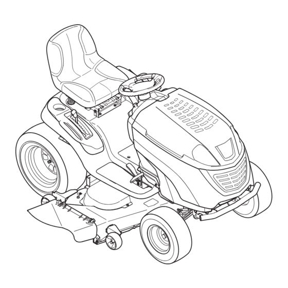
Controls and Features Systems Indicator Monitor Electric PTo Button (optional) Throttle/Choke Control Ignition Switch Module Brake Pedal Drive Pedal Parking Brake/ Reverse Pedal Cruise Control Lever Seat Adjustment Lever (optional) Deck Lift Lever Manual PTo Lever (optional) Storage Bin Figure 4-1 Brake Pedal Lawn Tractor controls and features are illustrated in Fig. - Page 13 Deck Lift Lever Systems Indicator Monitor/ Hour Meter LCD Found on your tractor’s right fender, the deck lift lever is used to change When the ignition key is rotated out of the height of the cutting deck. To the STOP position but not into the START HOURS 1/10 use, move the lever to the left, then position, the systems indicator monitor...
- Page 14 PTO/Blade Engage Handle Parking Brake/Cruise Control Lever (If Equipped) Activating the PTO engages power to the cutting deck or other (separately available) attachments. Push forward on the PTO/Blade Engage handle to activate it. Pull the PTO/Blade Engage handle back to disengage the power to the cutting deck or other (separately available) attachments.
-
Page 15: Operation
Operation Starting the Engine WARNING! Do not operate the tractor if the TO AVOID SERIOUS INJURY OR DEATH interlock system is malfunctioning. This system was designed for your safety and protection. • GO UP AND DOWN SLOPES, NOT ACROSS. • AVOID SUDDEN TURNS. NOTE: Refer to the Set-Up and Assembly section of this manual •... - Page 16 Driving The Tractor Reverse Caution Mode WARNING! The REVERSE CAUTION MODE position of the key switch module Avoid sudden starts, excessive speed allows the tractor to be operated in reverse with the blades (PTO) and sudden stops. engaged. NOTE: Mowing in reverse is not recommended. Lightly press the brake pedal to release the parking brake.
- Page 17 Driving On Slopes Cruise Control WARNING! Never engage the cruise control lever Refer to the SLOPE GAUGE on page 8 to help determine slopes while traveling in reverse. where you may operate the tractor safely. WARNING! Do not mow on inclines with a slope in excess of 15 degrees (a rise of approximately 2-1⁄2 To set the cruise control: feet every 10 feet).
- Page 18 Engaging the PTO • For best results it is recommended that the first two laps be cut with the discharge thrown towards the center. After the Engaging the PTO transfers power to the cutting deck or other first two laps, reverse the direction to throw the discharge (separately available) attachments.
-
Page 19: Maintenance & Adjustment
Maintenance & Adjustments Maintenance Schedule Before Every Every Every Every Prior Each use 10 Hours 25 Hours 50 Hours 100 Hours to Storing Clean Hood/Dash Louvers Check Engine Oil Level Check Air Filter for Dirty, Loose or Damaged Parts Clean and Re-oil Air Filter’s Foam Precleaner Replace Air Filter Element Change Engine Oil and Replace Oil Filter Clean Battery Terminals... - Page 20 Pop open the protective cap on the end of the oil drain Air Cleaner valve to expose the drain port. See Fig 6-1. Service the pre-cleaner and cartridge/air cleaner element as instructed in the separate engine manual. Spark Plug The spark plug should be cleaned and the gap reset once a season.
- Page 21 Lubrication Attach the hose coupler to the water port on your decks surface. See Fig. 6-2. WARNING! Before lubricating, repairing, or inspecting, always disengage PTO, set parking brake, stop engine and remove key to prevent unintended starting. Front Wheels Each of the front wheel axles and rims is equipped with a grease fitting.
- Page 22 Deck Spindle Grease fittings can be found on each deck spindle. See Fig. 6-4. Lubricate with 251H EP grease or an equivalent No. 2 multi- purpose lithium grease. Using a grease gun, apply two strokes (minimum) or sufficient grease to the spindle shaft. Figure 6-5 lower the front of the deck, loosen (thread outward) the hex nut, away from the front hanger bracket.
- Page 23 Steering Adjustment If the tractor turns tighter in one direction than the other, or if the ball joints are being replaced due to damage or wear, the steering drag links may need to be adjusted. Adjust the drag links so that equal lengths of each are threaded into the ball joint on the left side and the ball joint on the right side: Remove the hex nut on the top of ball joint.
-
Page 24: Service
Service Cutting Deck Removal To remove the cutting deck, proceed as follows: Place the PTO/Blade Engage knob in the disengaged (OFF) position and engage the parking brake. Lower the deck by moving the deck lift lever into the bottom notch on the right fender. Insert Ratchet Locate the PTO clutch under the front of your tractor. - Page 25 Figure 7-6 Figure 7-4 Cutting Blades To properly sharpen the cutting blades, remove equal amounts of metal from both ends of the blades along the WARNING! cutting edges, parallel to the trailing edge, at a 25°- to 30° Shut the engine off and remove angle.
- Page 26 Battery Fuse CALIFoRNIA PRoPoSITIoN 65 WARNING WARNING! Before servicing, repairing, or Battery posts, terminals, and related accessories inspecting, always disengage PTO, set parking contain lead and lead compounds, chemicals known brake, stop engine and remove key to prevent to the State of California to cause cancer and unintended starting.
- Page 27 Front Spindle Pulley Hex Screws Deck Idler Pulleys Belt Keeper Rod Belt Guards Deck Idler Pulley outer Spindle Pulleys Figure 7-7 Figure 7-8 Then route the belt around the two deck idler pulleys as shown in Fig. 7-8. Retighten the belt keeper rod loosened earlier. Remount the belt guards removed earlier.
-
Page 28: Troubleshooting
Troubleshooting Problem Cause Remedy Engine fails to start PTO/Blade Engage knob engaged. Place knob in disengaged (OFF) position. Parking brake not engaged. Engage parking brake. Spark plug wire(s) disconnected. Connect wire(s) to spark plug(s). Throttle control lever not in correct starting Place throttle lever to FAST position. -
Page 29: Specifications
Specifications GT2200 Capacities Fuel Tank 3.0 gal. (11.4 liters) Engine Crankcase (w/ filter) 57.5 oz. (1.7 liters) Hydrostatic Transmission Forward Speed 0 - 6.4 mph (10.2 km/h) Reverse Speed 0 - 2.5 mph (4.0 km/h) Engine (Air-cooled, 4-cycle) Make Kohler Courage Model SV730 n i l... -
Page 30: Electrical Diagrams
Electrical Diagram GT2200... - Page 31 CALIFORNIA EMISSION CONTROL WARRANTY STATEMENT YOUR WARRANTY RIGHTS AND OBLIGATIONS The California Air Resources Board and MTD Consumer Group Inc are pleased to explain the evaporative emission control system warranty on your 2008 lawn mower. In California, new lawn mowers must be designed, built and equipped to meet the State’s stringent anti-smog standards. MTD Consumer Group Inc must warrant the EECS on your lawn mower for the period of time listed below provided there has been no abuse, neglect or improper maintenance of your lawn mower.
-
Page 32: Emission Control Warranty Statement
WARRANTED PARTS: The repair or replacement of any warranted part otherwise eligible for warranty coverage may be excluded from such warranty coverage if MTD Consumer Group Inc demonstrates that the lawn mower has been abused, neglected, or improperly maintained, and that such abuse, neglect, or improper maintenance was the direct cause of the need for repair or replacement of the part. - Page 33 The Toro Company MANUFACTURER’S LIMITED WARRANTY FOR LAWN & GARDEN TRACTORS IMPORTANT: To obtain warranty coverage owner must present an Without limiting the foregoing, this limited warranty does not pro- original proof of purchase and applicable maintenance records to vide coverage in the following cases: the servicing dealer.
-
Page 34: Warranty
Notes... - Page 35 Notes...