Table of Contents
Advertisement
Quick Links
Please read these instructions carefully before using this product, and save this manual for future use.
A firmware update has been made available to improve camera capabilities and to add functionality.
≥ For information about functions that have been added or modified, refer to the pages for
GD GT
Operating Instructions
Model No.
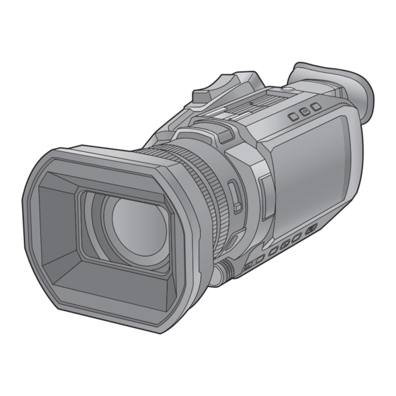
4K Video Camera
HC- X1500
HC- X2000
HC- X2050
"Firmware
Update".
DVQP2162VA
F0220SQ4043
Advertisement
Table of Contents

Related Manuals for Panasonic HC-X2050


Summary of Contents for Panasonic HC-X2050
- Page 1 Operating Instructions 4K Video Camera HC- X1500 Model No. HC- X2000 HC- X2050 Please read these instructions carefully before using this product, and save this manual for future use. A firmware update has been made available to improve camera capabilities and to add functionality. ≥...
-
Page 2: Information For Your Safety
Information for Your Safety Information for Your Safety WARNING: To reduce the risk of fire, electric shock or product damage, ≥ Do not expose this unit to rain, moisture, dripping or splashing. ≥ Do not place objects filled with liquids, such as vases, on this unit. ≥... - Page 3 Specific small output wireless device Product name: (wireless device for wireless data communication system) Representative TEL No. for servicing: 1588-8452 (Panasonic) Manufacturer: Panasonic Entertainment & Communication Co., Ltd. Country of origin: Made in Malaysia Certificate holder: Panasonic Korea Ltd. R-C-PKL-AG-CX10 R-C-PKL-HC-X1500 ∫...
- Page 4 ≥ A battery pack with visible swelling may be dangerous. Contact your dealer or a Panasonic service center. ≥ Do not use the battery pack with any equipment or charger other than the ones specified in the Panasonic Operating Instructions.
- Page 5 Information for Your Safety For the HC-X1500GT/HC-X2000GT Emergency Treatment Methods Emergency Treatment Methods In order to prevent loss of life or personal property To avoid danger and loss of life and property to the user and others, remove the battery for the user as well as others, please unplug the and stop using the device if an abnormality power and stop using the device immediately...
- Page 6 To ensure that safe products are used we would recommend that a genuine Panasonic battery pack is used. ∫ The symbols on this product (including the accessories) represent the following: Standby Í...
- Page 7 Select “LICENSE.TXT” in the external drive recognized by the computer. At least three (3) years from delivery of this product, Panasonic will give to any third party who contacts us at the contact information provided below, for a charge no more than our cost of physically performing source code distribution, a complete machine-readable copy of the corresponding source code covered under GPL V2.0 or LGPL V2.1, as well as the respective copyright notice thereof.
- Page 8 ∫ Conventions used in this manual ≥ Words and phrases in [ ] brackets indicate content displayed in the LCD monitor. ≥ Words and phrases in < > brackets indicate design text used on this unit, such as button names. ∫...
-
Page 9: Table Of Contents
Contents Contents Information for Your Safety.............2 Operating the menu ................61 Initializing the menu ................62 Chapter 1 Overview Menu settings................. 63 [THUMBNAIL] menu .................63 [CAMERA] menu ................64 Before using the unit ..............12 [SCENE FILE] menu.................67 Accessories/Optional accessories..........15 [AUDIO] menu ..................72 Accessories..................15 [VIDEO OUT/LCD/VF] menu ............74 Optional accessories................ - Page 10 Contents Chapter 10 Notes Convenient shooting functions ..........133 Zebra patterns display ..............133 Displaying the marker ..............133 Frequently asked questions ............184 Focus assist function ..............134 Power supply ..................184 Face detection/tracking AE&AF function ........137 Battery ....................184 Optical image stabilizer function ............ 137 Memory card...................184 Dynamic range stretcher function ..........
-
Page 11: Chapter 1 Overview
Overview Chapter 1 Before using the unit, read this chapter. -
Page 12: Before Using The Unit
Chapter 1 Overview — Before using the unit Before using the unit ∫ Before using the unit, always check if the built-in battery is not consumed, and then set the date/time. The date of the internal clock of the unit resets to January 1, 2020 if the built-in battery is exhausted. This may result in the meta data of the clip not being recorded correctly, and it may not display correctly in the thumbnail screen. - Page 13 ≥ If you prepare to record important images, always shoot some advance test footage to verify that both pictures and sound are being recorded normally. ≥ Panasonic will not assume liability when video or audio recording fails due to a malfunction of the unit or the memory card during the use.
- Page 14 ≥ Remove the Memory Card from this unit when requesting a repair. ≥ Settings may return to factory default when this unit is repaired. ≥ Please contact the dealer where you purchased this unit or Panasonic if above operations are not possible due to malfunction. ≥ (For the...
-
Page 15: Accessories/Optional Accessories
Chapter 1 Overview — Accessories/Optional accessories Accessories/Optional accessories Accessories Check the accessories before using this unit. Product numbers correct as of August 2020. These may be subject to change. Battery pack (l 27) Eye cup (l 31) AG-VBR59 DVZE1040Z AC adaptor (l 28) SAE0011A ∫... -
Page 16: When Turning On The Power For The First Time
Chapter 1 Overview — When turning on the power for the first time When turning on the power for the first time The time zone, date, and time are not set when the unit is shipped. [TIME ZONE] is displayed in the LCD monitor when the power is turned on for the first time. Follow the guidance and make the settings in the order of [TIME ZONE] and then [CLOCK SETTING]. -
Page 17: What You Can Do With This Unit
Chapter 1 Overview — What you can do with this unit What you can do with this unit Recording to the memory card Recording in following types is possible. ≥ MOV recording (UHD and FHD recording) ≥ MP4 recording (UHD and FHD recording) ≥... -
Page 18: Connecting To The Network
Chapter 1 Overview — What you can do with this unit Connecting to the network This unit is equipped with wireless LAN. It can connect to wireless LAN devices via a network. Available functions When the unit is connected to a network, the following functions are available. ∫... -
Page 19: Chapter 2 Description Of Parts
Description of Parts Chapter 2 This chapter describes the names, functions, and operations of parts on the unit. -
Page 20: Main Unit
Chapter 2 Description of Parts — Main unit Main unit The illustrations in this document show the handle unit ( supplied, optional) removed. X2000 X2050 X1500 13 14 15 Lens hood (l 30) <USER2> button (l 49, 108) Lens cover switching lever (l 31) Used as a USER button (USER2). - Page 21 Chapter 2 Description of Parts — Main unit <SHUTTER> button (l 111) <EXIT> button Switches the shutter mode. Returns to one level higher when the menu is displayed. Pressing the <EXIT> button without confirming the setting value will not reflect the <GAIN>...
- Page 22 Chapter 2 Description of Parts — Main unit X2000 X2050 Status indicator (l 36) Headphones terminal Illuminates when power is on. Connects audio monitoring headphones. Battery release lever (l 27) Charging lamp (l 28) Used when removing the battery from the main unit. Illuminates when the battery is charging.
-
Page 23: Handle Unit ([X2000]/[X2050] Supplied, [X1500] Optional: Vw-Hu1)
Chapter 2 Description of Parts — Handle unit ([X2000]/[X2050] supplied, [X1500] optional: VW-HU1) Handle unit ([X2000]/[X2050] supplied, [X1500] optional: VW-HU1) 14 13 A With a microphone holder attached Handle <INPUT2> switch (l 125) Switches audio input signals connected to the <INPUT 2> terminal. Microphone holder mounting section (l 32) <LINE>: Select when audio equipment is connected by the line input. - Page 24 Chapter 2 Description of Parts — Handle unit ([X2000]/[X2050] supplied, [X1500] optional: VW-HU1) 22 23 17 18 19 Light cover ≥ Keep the Light cover out of reach of children to prevent swallowing. Built-in LED light (l 119) Tally lamp (l 54) Illuminates when the recording is started.
-
Page 25: Basic Operation
Chapter 2 Description of Parts — Basic operation Basic operation Multidial operation Operate the multidial on the main unit by turning it in vertical direction or pushing it. ≥ Turning the multidial in vertical direction will move the cursor. ≥ Pressing the multidial will select or confirm the item with cursor. ≥... -
Page 26: Chapter 3 Preparation
Preparation Chapter 3 Before you use the unit, attach the battery following the procedures in this chapter. The attaching of accessories is also described in this chapter. -
Page 27: Power Supply
Chapter 3 Preparation — Power supply Power supply A battery or the supplied AC adaptor can be used as the power supply for the unit. ≥ The unit is compatible to following batteries. (As of August 2020) j AG-VBR59 (supplied/optional, supports quick charging) j VW-VBD58 (optional) ≥... -
Page 28: Charging The Battery
NOTE 0 Do not use any other AC adaptors except the supplied one. 0 We recommend using Panasonic batteries (l 27). 0 If you use other batteries, we cannot guarantee the quality of this product. 0 Do not heat or expose to flame. - Page 29 Chapter 3 Preparation — Power supply Standard charging time and recordable time Continuous recordable time Voltage/capacity Charging time for Battery parts number [FREQUENCY] (minimum) main unit X1500 X2000 X2050 AG-VBR59 (supplied/optional) 7.28 V/5900 mAh Approx. 5 h 30 min [59.94Hz] Approx.
-
Page 30: Attaching Accessories
Chapter 3 Preparation — Attaching accessories Attaching accessories Adjusting the grip belt ≥ Adjust the grip belt so that it fits the size of your hand. ≥ If the buckle is difficult to tighten, move the pad backward and tighten the buckle again. ... -
Page 31: Attaching The Eye Cup
Chapter 3 Preparation — Attaching accessories Opening and closing the lens cover Use the lens cover switching lever to open and close the lens cover. Open the lens cover when shooting. When not using the unit, close the lens cover in order to protect the lens. NOTE 0 Do not press the lens cover with force. -
Page 32: Attaching The Handle Unit ([X2000]/[X2050] Supplied, [X1500] Optional)
Chapter 3 Preparation — Attaching accessories Attaching the handle unit ([X2000]/[X2050] supplied, [X1500] optional) ¥ Press the power button to turn off the unit. (l 36) Open the microphone holder. Open buckle 1, and detach fitting 2 from hook 3. ... - Page 33 Chapter 3 Preparation — Attaching accessories While pressing the handle unit mounting screw down, turn it in the direction indicated by arrow 2 until it stops. ∫ How to remove Remove by doing the steps for attaching in reverse. NOTE 0 Keep the microphone holder mounting screws out of reach of children to prevent swallowing.
-
Page 34: Attaching The External Microphone
Chapter 3 Preparation — Attaching accessories Attaching the external microphone ∫ Attaching an external microphone to the <INPUT 1>/<INPUT 2> terminals When the handle unit ( supplied, optional) is attached to the unit, you can attach an external microphone such as a X2000 X2050 X1500... -
Page 35: Attaching A Tripod
Chapter 3 Preparation — Attaching accessories ∫ Attaching an external microphone to the <MIC> terminal You can attach an external microphone that is compatible with the stereo mini jack. Attach the external microphone to the accessory shoe A. ≥ For details about how to attach the external microphone, refer to the operating instructions for the external microphone. -
Page 36: Turning On/Off The Power
Chapter 3 Preparation — Turning on/off the power Turning on/off the power Turning the unit on and off with the power button Open the LCD monitor and press the power button to turn on the unit. A The status indicator lights on. ∫... -
Page 37: Setting The Date/Time Of The Internal Clock
Chapter 3 Preparation — Setting the date/time of the internal clock Setting the date/time of the internal clock The date/time/time zone are recorded as meta data in the clip while shooting. This will affect the management of recorded clips, so always check and set the date/time and time zone before using the unit for the first time. Do not change the setting of the date/time and time zone while shooting. -
Page 38: Preparing The Memory Card
48 GB to 128 GB ≥ Operation is not guaranteed for any memory cards other than the above. ≥ Panasonic memory cards are recommended. ≥ The following memory cards cannot be used because they do not comply with the SD standards. -
Page 39: Preventing Unintentional Erasing
Chapter 3 Preparation — Preparing the memory card Preventing unintentional erasing Writing, erasing and formatting data is prohibited by setting the write-protection switch A of the memory card to the LOCK side. Status of the card access lamp and memory card Card access lamp Memory card status Orange (illuminated) -
Page 40: Inserting/Removing The Memory Card
Chapter 3 Preparation — Preparing the memory card Inserting/removing the memory card Inserting the memory card The memory card to use with the unit should always be formatted on the unit. (l 40) ≥ Formatting the memory card will erase all of the recorded data which cannot be restored. ... -
Page 41: Recording Time Of The Memory Card
Chapter 3 Preparation — Preparing the memory card Recording time of the memory card ≥ Memory cards are only mentioned with their main memory size. The stated times are the approximate recordable times for continuous recording. ≥ If recording for long periods, prepare batteries for 3 or 4 times the period you wish to record for. (l 29) ≥... - Page 42 Chapter 3 Preparation — Preparing the memory card When the file format is MP4 Recording capacity Recording format Recording rate 64 GB 128 GB 100 Mbps Approx. 1 h 20 min Approx. 2 h 40 min 72 Mbps Approx. 1 h 50 min Approx.
-
Page 43: Handling The Recording Data
Chapter 3 Preparation — Preparing the memory card Handling the recording data Folder structure example of a memory card Various important information is contained in the recording data, and it is linked with the folder structure and management files as shown in the figure. If such information is changed or deleted even partially, an error such as that the data cannot be recognized or the recording becomes impossible may occur. - Page 44 Chapter 3 Preparation — Preparing the memory card Folder name of the MOV format/MP4 format video data The fourth through eighth characters of the folder name differ depending on the setting of the unit. Folder number 001 to 999 (sequential number) Number of pixels R: 38402160 Y: 19201080...
- Page 45 Chapter 3 Preparation — Preparing the memory card About the number of clips that can be recorded to a memory card File format Number of clips Approx. 4000 ≥ The total number of clips for MOV and MP4. AVCHD Approx. 3900 ≥...
-
Page 46: Setting Of Time Data
Chapter 3 Preparation — Setting of time data Setting of time data The unit provides time code, user bits, and date and time (real time) data as time data, and records in each frame synchronized with the video. The time data is also recorded as the clip meta data. -
Page 47: Setting The Time Code
Chapter 3 Preparation — Setting of time data How to input user bits By setting user bits, information such as memos (date, time) up to 8 digits long (hexadecimal) can be recorded. Select the [RECORDING] menu [TC/UB] [UB MODE] [USER]. Select the [RECORDING] menu ... - Page 48 Chapter 3 Preparation — Setting of time data ∫ Setting range of time code The range of the time code that can be set differs depending on the frame rate of [REC FORMAT]. [FREQUENCY] Frame rate of [REC FORMAT] Range of the time code that can be set [59.94Hz] 59.94p, 29.97p, 59.94i 00:00:00:00 to 23:59:59:29...
-
Page 49: Assigning Function To The User Buttons
Chapter 3 Preparation — Assigning function to the USER buttons Assigning function to the USER buttons FLUO SPARK STILL CINE V CINE D AREA FACE DETECT ZEBRA MENU COUNTER RESET ... - Page 50 Chapter 3 Preparation — Assigning function to the USER buttons Item (USER button icon display) Description [ONE PUSH AF] ([ONE PUSH AF]) Assigns the one-push auto focus function. [S.GAIN] ([S.GAIN]) Assigns the function that switches to super gain. [AREA] ([AREA]) Assigns the area function.
-
Page 51: Checking The Function Assigned To The User Buttons
Chapter 3 Preparation — Assigning function to the USER buttons USER button functions Menu settings [SYSTEM] menu [SUPER SLOW] [SUPER SLOW] [VIDEO OUT/LCD/VF] menu [LEVEL GAUGE] [LEVEL GAUGE] [LEVEL GAUGE] [VIDEO OUT/LCD/VF] menu [FOCUS ASSIST] [DETAIL] [LCD/VF DETAIL] [OTHERS] menu ... -
Page 52: Adjusting And Setting The Lcd Monitor
Chapter 3 Preparation — Adjusting and setting the LCD monitor Adjusting and setting the LCD monitor Using the LCD monitor This unit is equipped with a 3.5-inch LCD monitor. Use either the viewfinder or the LCD monitor depending on your purpose and the shooting conditions. Open the LCD monitor. -
Page 53: Adjusting And Setting The Viewfinder
Chapter 3 Preparation — Adjusting and setting the viewfinder Adjusting and setting the viewfinder This unit is equipped with a 0.24-inch viewfinder. Use either the viewfinder or the LCD monitor depending on your purpose and the shooting conditions. Using the viewfinder When the LCD monitor is difficult to use because the surroundings are bright, you can check the image using the viewfinder. -
Page 54: Tally Lamp
Chapter 3 Preparation — Tally lamp Tally lamp When the handle unit ( supplied, optional) is attached to the unit, the tally lamp can be illuminated during recording. X2000 X2050 X1500 Select the [OTHERS] menu [HANDLE TALLY LED] [ON]. ≥... -
Page 55: Chapter 4 Operation
Operation Chapter 4 This chapter describes how to operate the screen of this unit, how to operate the menu, the structure of the menu, and details of the menu. -
Page 56: Basic Operation Of The Screen
Chapter 4 Operation — Basic operation of the screen Basic operation of the screen Major button operation and screen display 1 <THUMBNAIL> button 2 <DISP/MODE CHK> button ∫ <THUMBNAIL> button Displays the thumbnail screen. Playback, copy, delete, or protect of a clip can be performed. For details about the thumbnail screen, refer to “Thumbnail operation”. -
Page 57: Major Button Operation And Switching Screen
Chapter 4 Operation — Basic operation of the screen Major button operation and switching screen The screens switch as shown below when you press the <DISP/MODE CHK> button, <EXIT> button, <THUMBNAIL> button, or multidial. TCR 01 : 09 : 44. 23 TCR 01 : 09 : 44. -
Page 58: Operating Each Screen
Chapter 4 Operation — Operating each screen Operating each screen Camera image screen Displays the shooting screen. For details about the camera image screen, refer to “Screen status display”. (l 158) Thumbnail screen Playback, copy, delete, or protect of a clip can be performed. For details about the thumbnail screen, refer to “Thumbnail operation”. -
Page 59: Basic Operation Of The Menu
Chapter 4 Operation — Basic operation of the menu Basic operation of the menu The setting of the unit can be changed with the menu in accordance to the shooting scene or recording contents. Set data is written and saved in the main unit memory. ≥... -
Page 60: Displaying The Menu
Chapter 4 Operation — Basic operation of the menu Displaying the menu Displays the menu, and select the menu or item to set. Press the <MENU> button. The menu is displayed. [`]/[{] Switches the page or changes the value when selected. These button icons are not available if they cannot be changed. -
Page 61: Operating The Menu
Chapter 4 Operation — Basic operation of the menu Operating the menu Various settings are possible from the menu. There are 2 methods of operation: a method to operate with the multidial, or a method to touch the LCD monitor. When operating with the multidial Operate the multidial on the main unit by turning it in vertical direction or pushing it. -
Page 62: Initializing The Menu
Chapter 4 Operation — Basic operation of the menu When operating by touching the LCD monitor Operate by touching the LCD monitor. Fig. 1 Fig. 2 Press the <MENU> button. The menu is displayed. Select the menu to set. The lower level menu is displayed. ≥... -
Page 63: Menu Settings
Chapter 4 Operation — Menu settings Menu settings [THUMBNAIL] menu Performs confirmation or deleting of the recording clip. This menu can be set when the thumbnail screen is displayed. [PLAYBACK] Sets the playback of recorded clips. [ALL SLOT] will always be selected when you switch from the camera image screen to the thumbnail screen. [CLIP SEL] Selects a clip to be displayed on the thumbnail screen. -
Page 64: [Camera] Menu
Chapter 4 Operation — Menu settings [CAMERA] menu Sets the basic functions of the camera. This menu cannot be set when the thumbnail screen is displayed. [SW MODE] [ZOOM RING] Sets the rear ring 1 direction and zoom control when performing zoom operations. [DOWN TELE] Zooms in when turned towards the B side. - Page 65 Chapter 4 Operation — Menu settings [ATW] You can set ATW (auto tracking white balance function) when the <WHITE BAL> button is pressed. [Ach] If you have pressed the <WHITE BAL> button to switch to [Ach], this is set to [ATW]. [Bch] If you have pressed the <WHITE BAL>...
- Page 66 Chapter 4 Operation — Menu settings [AUTO SLOW SHTR] You can make images brighter by making the shutter speed slower in dark places. The slow shutter works when in the auto shutter mode. The items that can be set are as follows. ≥...
-
Page 67: [Scene File] Menu
Chapter 4 Operation — Menu settings [USER4] Sets the function to assign to the <USER4> button. (Factory setting: [AE LEVEL]) [USER5] Sets the function to assign to the <USER5> button. (Factory setting: [REC CHECK]) [USER6] Sets the function to assign to the [USER6] button icon. (Factory setting: [AWB]) [USER7] Sets the function to assign to the [USER7] button icon. - Page 68 Chapter 4 Operation — Menu settings [NAME EDIT] Edits the name of the scene file selected in the scene file menu. (Maximum 8 characters) ≥ Refer to page 100 for setting procedures. [LOAD/SAVE/INITIALIZE] Loads/saves/initializes the setting values of the scene file assigned to the current scene file number (any one from 1 to 6). [LOAD] Selects and loads the scene file saved in the internal memory of the unit.
- Page 69 Chapter 4 Operation — Menu settings [CHROMA LEVEL] Sets the chroma level of P and P signals. The items that can be set are as follows. ≥ [j50]…[i50] [CHROMA PHASE] Finely adjusts the chroma phase of the P signal and P signal.
- Page 70 Chapter 4 Operation — Menu settings [B-B-Cy] [SAT] Corrects the color saturation between blue and the color which is intermediate between blue and cyan. [PHASE] Corrects the hue between blue and the color which is intermediate between blue and cyan. The items that can be set are as follows.
- Page 71 Chapter 4 Operation — Menu settings [SKIN TONE DTL.] The skin of human subjects can be made to appear smoother when recorded. The items that can be set are as follows. ≥ [ON], [OFF] NOTE 0 If the background or anything else in the scene has colors similar to the skin color, they will also be smoothed. 0 If the brightness is insufficient, the effect may not be clear.
-
Page 72: [Audio] Menu
Chapter 4 Operation — Menu settings [DRS EFFECT DEPTH] Sets the compression level of the high luminosity areas of the dynamic range stretcher function. By compressing the video signal levels of the high luminosity areas that are blown out in normal shooting, the dynamic range can be expanded. The items that can be set are as follows. - Page 73 Chapter 4 Operation — Menu settings [INPUT2 LINE LEVEL] Sets the audio input level of the audio device connected to the <INPUT 2> terminal. Enabled when the audio device is connected and the <INPUT2> switch is set to <LINE>. The items that can be set are as follows. ≥...
-
Page 74: [Video Out/Lcd/Vf] Menu
Chapter 4 Operation — Menu settings [MIC LIMITER LINK] Sets whether to make the limiter work on the other audio channel when the limiter works in either audio channel 1 or audio channel 2. The items that can be set are as follows. ≥... - Page 75 Chapter 4 Operation — Menu settings NOTE 0 For the combinations that can be set, refer to “Format that can be output from the <SDI OUT> terminal [X2000]/[X2050]”. ( l 156) [SDI AUDIO GAIN CHG] Adjusts the gain for the audio signal output from the <SDI OUT> terminal. The items that can be set are as follows.
- Page 76 Chapter 4 Operation — Menu settings [HDMI OUT CHAR] Sets whether to superimpose the character to the output from the <HDMI> terminal. [ON] Superimposes. [OFF] Does not superimpose. (Factory setting: [OFF]) [HDMI OUT ZEBRA] Sets whether to superimpose the zebra signal to the output from the <HDMI> terminal. The settings of the zebra signal follow the zebra signal settings in the [VIDEO OUT/LCD/VF] menu ...
- Page 77 Chapter 4 Operation — Menu settings [VF] ≥ These settings will not affect the images actually recorded. [BRIGHTNESS] Adjusts the brightness of the viewfinder. The items that can be set are as follows. ≥ [j15]…[i15] (Factory setting: [0]) [COLOR LEVEL] Adjusts the color level of the viewfinder.
- Page 78 Chapter 4 Operation — Menu settings [BATTERY REMAIN] Switches display/hide of the power status. The items that can be set are as follows. ≥ [ON], [OFF] (Factory setting: [ON]) [REC FORMAT] Switches display/hide of the recording format settings. The items that can be set are as follows. ≥...
- Page 79 Chapter 4 Operation — Menu settings [GAIN] Switches display/hide of the gain value. The items that can be set are as follows. ≥ [ON], [OFF] (Factory setting: [ON]) [ND FILTER] Switches display/hide of the ND filter transmittance rate. The items that can be set are as follows. ≥...
- Page 80 Chapter 4 Operation — Menu settings [D.ZOOM] Switches display/hide of digital zoom ratio. The items that can be set are as follows. ≥ [ON], [OFF] (Factory setting: [ON]) [IR REC] Switches display/hide of the settings in the [CAMERA] menu [SW MODE] [IR REC]. The items that can be set are as follows.
- Page 81 Chapter 4 Operation — Menu settings [PEAKING LEVEL] Sets the intensity of the peaking display. The items that can be set are as follows. ≥ [LOW], [MID], [HIGH] (Factory setting: [MID]) [PEAKING COLOR] Sets the color of the peaking display. The items that can be set are as follows.
-
Page 82: [Recording] Menu
Chapter 4 Operation — Menu settings [WFM TRANSPARENCE] Sets the transmittance of the waveform monitor. The items that can be set are as follows. ≥ [0%], [25%], [50%] (Factory setting: [25%]) [LEVEL GAUGE] [LEVEL GAUGE] Switches display/hide of the level gauge. The items that can be set are as follows. - Page 83 Chapter 4 Operation — Menu settings [REC FUNCTION] [REC MODE] Selects the recording mode. [NORMAL] Performs the standard recording. [INTERVAL] Performs the interval recording. (l 131) (Factory setting: [NORMAL]) [INTERVAL TIME] Sets the interval duration for interval recording. The items that can be set are as follows. ≥...
-
Page 84: [Network] Menu
Chapter 4 Operation — Menu settings [UB MODE] Selects the user bits mode. User bits information is recorded in the clip. [FRAME RATE] Selects the image information (such as frame rate) of the camera. [USER] Selects the user bits set in [UB PRESET]. [TIME] Selects the local time. - Page 85 Chapter 4 Operation — Menu settings [IP REMOTE] Perform settings for the IP remote (remote operation by the HC ROP app). [ENABLE/DISABLE] Sets whether to enable the IP remote function. The items that can be set are as follows. ≥ [ENABLE], [DISABLE] (Factory setting: [DISABLE]) [USER ACCOUNT] Registers a new user account to use for authentication in the network function of the unit.
- Page 86 Chapter 4 Operation — Menu settings [START TRIGGER] Sets whether to start streaming with operation of the unit or operation of the application software. The items that can be set are as follows. ≥ [CAMERA], [RECEIVER], [RECEIVER(MULTICAST)] (Factory setting: [RECEIVER]) [CONNECTION INFO.] Selects the internal memory of the unit or the memory card as the reference location for the transfer destination when starting a stream with the operation of the unit.
- Page 87 Chapter 4 Operation — Menu settings [CHANNEL] Sets the channel to be used when connected to the wireless LAN with following items set. ≥ The [NETWORK] menu [WLAN PROPERTY] [TYPE] [DIRECT] The items that can be set are as follows. ≥...
-
Page 88: [System] Menu
Chapter 4 Operation — Menu settings [UTILITY] Performs the various operations related to the network function. [NETWORK INITIALIZE] Returns the various networks settings to the factory default state and restarts the unit. [SYSTEM] menu Configure the settings regarding the recording format of video and audio. [FREQUENCY] Sets the system frequency. -
Page 89: [Others] Menu
Chapter 4 Operation — Menu settings [SUPER SLOW] Sets the super slow recording. Enable this setting to shoot slow motion video. The items that can be set are as follows. ≥ [ON], [OFF] (Factory setting: [OFF]) NOTE 0 In the following cases, it is fixed to [OFF]. j When the setting is other than [SYSTEM] menu ... - Page 90 Chapter 4 Operation — Menu settings [CLOCK] [CLOCK SETTING] Sets the calendar (date of the built-in clock) and time. Year [2018]…[2037] Month [JAN]…[DEC] ([1]…[12]) [1]…[31] (This changes according to the year and month settings) Hour [0]…[23] Minute [0]…[59] [TIME ZONE] Sets the time zone.
- Page 91 Chapter 4 Operation — Menu settings [UPDATE] Updates the firmware. Insert the memory card where the update file is saved into card slot 1. The items that can be selected are as follows. ≥ [YES], [NO] [ECO MODE] By setting [OTHERS] menu [ECO MODE] [BATTERY]/[AC]/[NETWORK], when there is no button operation or LCD monitor touch operation performed for a certain time, the power turns off automatically.
-
Page 92: Factory Setting Value Of The Scene File
Chapter 4 Operation — Factory setting value of the scene file Factory setting value of the scene file [SCENE FILE] menu The factory settings of the [SCENE FILE] menu and the items that can be selected differ depending on the [SCENE FILE] menu [FILE SELECT] setting. -
Page 93: Target Items For Scene File/Setup File/Initialization
Chapter 4 Operation — Target items for scene file/setup file/initialization Target items for scene file/setup file/initialization ≥ SCENE: Items saved in scene files. ≥ SETUP: Items saved in setup files. ≥ INITIALIZE: Items that are initialized with the [OTHERS] menu [MENU INITIALIZE]. ≥... -
Page 94: [Scene File] Menu
Chapter 4 Operation — Target items for scene file/setup file/initialization [SCENE FILE] menu Item SCENE SETUP INITIALIZE [NAME EDIT] — [LOAD/SAVE/INITIALIZE] — — — [MASTER DTL] — [DTL CORING] — [V.DTL LEVEL] — [RB GAIN CONTROL [R GAIN AWB A] —... -
Page 95: [Audio] Menu
Chapter 4 Operation — Target items for scene file/setup file/initialization [AUDIO] menu Item SCENE SETUP INITIALIZE [HANDLE UNIT INPUT [INPUT1 MIC LEVEL] — SETTING] [INPUT2 MIC LEVEL] — [INPUT1 LINE LEVEL] — [INPUT2 LINE LEVEL] — [MIC SETTING] [CH1 LEVEL] —... - Page 96 Chapter 4 Operation — Target items for scene file/setup file/initialization Item SCENE SETUP INITIALIZE [INDICATOR] [FULL AUTO] — [SLOT1/2 STATUS] — [2 SLOTS FUNC.] — [STREAMING] — [NETWORK] — [BATTERY REMAIN] — [REC FORMAT] — [FRAME RATE] — [CLIP NAME] —...
-
Page 97: [Recording] Menu
Chapter 4 Operation — Target items for scene file/setup file/initialization [RECORDING] menu Item SCENE SETUP INITIALIZE [FORMAT MEDIA] — — — [CLIP NAME] [CAM INDEX] — — [NEXT CARD COUNT] — — [2 SLOTS FUNC.] — [PRE REC] — [REC FUNCTION] [REC MODE] —... -
Page 98: [Others] Menu
Chapter 4 Operation — Target items for scene file/setup file/initialization [OTHERS] menu Item SCENE SETUP INITIALIZE [FILE] [SCENE FILE(SD CARD)] — — — [SETUP FILE(SD CARD)] — — — [SETUP FILE(MEMORY)] — — — [SLOT FOR LOAD/SAVE] — [HANDLE TALLY LED] —... -
Page 99: Handling Setting Data
Chapter 4 Operation — Handling setting data Handling setting data Scene files File structure of the setting data The scene files of [F1:] to [F6:] can be saved in the main unit memory in accordance to the scene file number. What can be saved as a scene file is the setting contents of the [SCENE FILE] menu. - Page 100 Chapter 4 Operation — Handling setting data Select [Enter]. A confirmation screen is displayed. Select [SET]. The file is saved. ≥ An error message may be displayed. For details about the error message, refer to “Cases indicated by error messages”. (l 187) ∫...
-
Page 101: Setup File
Chapter 4 Operation — Handling setting data Setup file You can save the setting information for this unit to the main unit memory or a memory card in card slot 1, and load it from a memory card into this unit. Saving the setup file The setup file can be overwritten to a file on the main unit memory or memory card in card slot 1, or saved as a new file. -
Page 102: Chapter 5 Shooting
Shooting Chapter 5 This chapter describes the basic procedure for recording. This chapter also describes the special recording method. -
Page 103: Shooting
Chapter 5 Shooting — Shooting Shooting For shooting, use the following steps. ≥ To use the REC button (on the handle) and tally lamp, attach the handle unit ( supplied, optional) to the unit. X2000 X2050 X1500 ... -
Page 104: Selecting The Resolution, Codec, And Frame Rate For Recording Video
Chapter 5 Shooting — Shooting Check videos recorded By pressing either the USER button assigned to [REC CHECK] or touching the USER button icon after recording, you can automatically play back the last approximately 3 seconds of the clip you have just recorded. * [REC CHECK] is set in the <USER5>... - Page 105 Chapter 5 Shooting — Shooting When [FILE FORMAT] is set to [MOV] ∫ Video Resolution [FREQUENCY] [REC FORMAT] YUV, number of bits Average bit rate UHD (38402160) [59.94Hz] [2160-59.94p/420LongGOP 150M] 4:2:0 8 bit 150 Mbps (VBR) [2160-59.94p/HEVC LongGOP 200M] 4:2:0 10 bit 200 Mbps (VBR) [2160-59.94p/HEVC LongGOP 100M] 100 Mbps (VBR)
- Page 106 Chapter 5 Shooting — Shooting When [FILE FORMAT] is set to [AVCHD] ∫ Video Resolution [FREQUENCY] [REC FORMAT] YUV, number of bits Average bit rate FHD (19201080) [59.94Hz] [1080-59.94p/AVCHD PS] 4:2:0 8 bit 25 Mbps (VBR) [1080-59.94i/AVCHD PH] 21 Mbps (VBR) [1080-59.94i/AVCHD HA] 17 Mbps (VBR) [1080-23.98p/AVCHD PH]...
-
Page 107: Adjustable Settings When Shooting
Chapter 5 Shooting — Adjustable settings when shooting Adjustable settings when shooting Adjust the iris and gain when shooting. ≥ You can adjust the iris (the lens stop) and the AE level (exposure compensation) with the rear ring or the multi manual function. ≥... -
Page 108: Gain
Chapter 5 Shooting — Adjustable settings when shooting Applications for the USER button When adjusting the iris (the lens stop), it is convenient to use the following USER button functions. [BACKLIGHT] Switches to the auto iris control for backlight compensation. Prevents the subject darkening due to backlight coming from behind and hitting them, so you can brighten the images on the screen. -
Page 109: Ae Level (Exposure Compensation)
Chapter 5 Shooting — Adjustable settings when shooting AE level (exposure compensation) AE LEVEL A Exposure compensation value +1.0EV AE LEVEL Adjusting with the rear ring Select the [SCENE FILE] menu [AE LEVEL] [ON]. Select the [CAMERA] menu [SW MODE] [REAR RING] [IRIS/AE LEVEL]. When the <AUTO/MANU>... -
Page 110: Brightness Adjustment
Chapter 5 Shooting — Adjustable settings when shooting Brightness adjustment When the external light is strong, you can switch the ND filter (brightness adjustment filter) to use with the <ND FILTER> switch. Change the setting of the <ND FILTER> switch. <1/64>: Reduces the amount of light entering the MOS sensor to 1/64. -
Page 111: Setting The Shutter Speed
Chapter 5 Shooting — Adjustable settings when shooting Setting the shutter speed A Shutter speed ≥ [A.SHTR] is displayed when the auto shutter mode is on. SHUTTER SHUTTER 1/60 Switch to manual mode with the <AUTO/MANU> switch. (l 103) Press the <SHUTTER>... - Page 112 Chapter 5 Shooting — Adjustable settings when shooting Operation of area mode function The function set in the [CAMERA] menu [SW MODE] [AREA MODE] can be used by performing the following operation when shooting or while in shooting standby. Either press the USER button assigned to [AREA] or touch the USER button icon.
-
Page 113: Adjusting The White And Black Balance
Chapter 5 Shooting — Adjusting the white and black balance Adjusting the white and black balance To obtain high-quality video at all times using the unit, the white and black balance must be adjusted according to conditions. Adjust the AWB (white balance adjustment), ABB (black balance adjustment), and AWB (white balance adjustment) in order to obtain higher image quality. - Page 114 Chapter 5 Shooting — Adjusting the white and black balance ∫ White pattern ≥ A white object (cloth or wall) near the subject may also be used for the white pattern. ≥ Required size of white pattern is as follows. ...
- Page 115 Chapter 5 Shooting — Adjusting the white and black balance Setting the variable value for the white balance The color temperature of white balance can be adjusted by the setting menu. Press the <WHITE BAL> button to switch to “Preset”. Either press the USER button assigned to [AWB] or touch the USER button icon to switch to “VAR”.
-
Page 116: Black Balance Adjustment
Chapter 5 Shooting — Adjusting the white and black balance Black balance adjustment Black balance must be adjusted in the following instances: ≥ When the unit is used for the first time ≥ When used after a long period of time without use ≥... -
Page 117: Using The Zoom Function
Chapter 5 Shooting — Using the zoom function Using the zoom function Adjust the angle of view you want to shoot. The unit has a 24 optical zoom. This can be expanded up to approximately 48 times (approximately 32 times in UHD recording) when the [CAMERA] menu [SW MODE] [i.ZOOM] ... - Page 118 Chapter 5 Shooting — Using the zoom function Using fast zoom When [FAST ZOOM] is assigned to a USER button, you can use fast zoom by operating the zoom lever (on the grip). Select the [CAMERA] menu [USER SW] [USER1] to [USER12] [FAST ZOOM]. Either press the USER button assigned to [FAST ZOOM] or touch the USER button icon.
-
Page 119: Using The Built-In Led Light
Chapter 5 Shooting — Using the built-in LED light Using the built-in LED light By attaching the handle unit ( supplied, optional), you can use the built-in LED light to brighten even dark places for recording. X2000 X2050 X1500 Slide the <LIGHT> switch to turn on/off the built-in LED light. ON: Light is on OFF: Light is off Adjust the amount of light from the built-in LED light... -
Page 120: Image Quality Adjustment
Chapter 5 Shooting — Image quality adjustment Image quality adjustment The image quality of the video to record can be set in the [SCENE FILE] menu. Measurement equipment such as a vector scope is necessary to change “Advanced settings”. Detail function This function thickens or weakens the outlines of images. -
Page 121: Color Correction Function
Chapter 5 Shooting — Image quality adjustment Color correction function This function sets color saturation and phase. Each of the 16 divisions of color hue can be set individually. Yl-R-R R-Mg Yl-Yl-R Mg-Mg-B [ ] [ ] G-Yl-Yl Mg-B-B G-G-Yl B-B-Cy Cy-G B-Cy-Cy... -
Page 122: Flash Band Compensation (Fbc) Function
Chapter 5 Shooting — Flash band compensation (FBC) function Flash band compensation (FBC) function This compensates for the phenomena of light and dark bands (flash bands) that horizontally divide images recorded in environments where there are flashes from other cameras, and reduces their effect. ... -
Page 123: Super Slow Recording Function
Chapter 5 Shooting — Super slow recording function Super slow recording function It is possible to acquire smooth slow motion video by shooting with a different frame rate from the frame rate to play back. This allows high-speed shooting of 120 fps/100 fps. In [SYSTEM] menu [FREQUENCY]/[FILE FORMAT]/[REC FORMAT], select the resolution, codec, and base frame rate for recording images. -
Page 124: Audio Input
Chapter 5 Shooting — Audio input Audio input The unit can record 2 channels of audio. When the handle unit ( supplied, optional) is attached to the unit, you can connect audio equipment or an external microphone X2000 X2050 X1500 to the <INPUT 1>/<INPUT 2>... -
Page 125: Using Audio Equipment/External Microphone (Xlr, 3-Pin)
Chapter 5 Shooting — Audio input Using audio equipment/external microphone (XLR, 3-pin) Attach the handle unit to the unit. Connect an audio device or an external microphone to the <INPUT 1>/<INPUT 2> terminal. Switch the connected audio input with the <INPUT1>/<INPUT2> switch. ... - Page 126 Chapter 5 Shooting — Audio input Automatic adjustment of the recording level ∫ When the handle unit is attached to the unit Switch the <CH1>/<CH2> switch to <AUTO>. ≥ The following settings are disabled when the <CH1>/<CH2> switch is switched to <AUTO>. j Recording level adjustments with the <AUDIO LEVEL CH1>/<AUDIO LEVEL CH2>...
-
Page 127: Monitoring The Audio
Chapter 5 Shooting — Audio input Monitoring the audio Audio recorded with the unit can be heard with a speaker or headphones. Audio is not output from the speaker during shooting. Setting the output audio Sets the audio channel and the format to be output from the headphone terminal. Select the [AUDIO] menu ... -
Page 128: Special Recording Function
Chapter 5 Shooting — Special recording function Special recording function Special recording such as pre-recording or relay recording is possible by setting the menu. Pre-recording Records the video and audio from specific time before the operation to start the recording. ... -
Page 129: Simultaneous Recording
Chapter 5 Shooting — Special recording function Press the REC button. ≥ The recording target switches to another memory card when the remaining recording capacity of one of the memory cards is exhausted during recording and relay recording starts. The number of the card slot that became the recording target is displayed with black and white inverted. Recording can be performed on 3 or more memory cards. -
Page 130: Background Recording
Chapter 5 Shooting — Special recording function Background recording If the memory cards are inserted into 2 card slots, set the background recording mode and then press the REC button to start recording simultaneously on card slot 1 and card slot 2. On card slot 1, recording can be repeatedly started and stopped as necessary by operating the REC button. On card slot 2, the recording operation continues as background recording. -
Page 131: Interval Recording
Chapter 5 Shooting — Special recording function Ending background recording Press and hold the USER button to which [BACKGR PAUSE] is assigned for approximately 5 seconds or touch and hold the USER button icon for approximately 5 seconds and release. The background recording stops on card slot 2. -
Page 132: Ir Recording
Chapter 5 Shooting — Special recording function IR recording A night time shooting using the IR light can be performed. ∫ Assigning [IR REC] to the USER button Select the [CAMERA] menu [USER SW] [USER1] to [USER12] [IR REC]. Set so enable/disable of the IR recording can be switched with a USER button. -
Page 133: Convenient Shooting Functions
Chapter 5 Shooting — Convenient shooting functions Convenient shooting functions Zebra patterns display The unit can display 2 types of zebra patterns to the output image from the LCD monitor. Select the [VIDEO OUT/LCD/VF] menu [EI ASSIST] [ZEBRA] [ON]. ≥... -
Page 134: Focus Assist Function
Chapter 5 Shooting — Convenient shooting functions Displaying the safety zone marker A safety zone marker can be displayed. Select the type of the frame in the [VIDEO OUT/LCD/VF] menu [MARKER] [SAFETY MARKER]. ≥ The safety zone marker is not displayed when [OFF] is selected. Displaying frame marker A frame marker can be displayed. - Page 135 Chapter 5 Shooting — Convenient shooting functions Press the USER button to which [FOCUS ASSIST] is assigned or touch the USER button icon. Press the USER button or touch the USER button icon again to return to the normal display. Pressing the <EXIT>...
- Page 136 Chapter 5 Shooting — Convenient shooting functions Enlarged display and peaking display settings Select the type of display in the [VIDEO OUT/LCD/VF] menu [FOCUS ASSIST] [FOCUS ASSIST SW]. [EXPAND]: Enables the enlarged display. [PEAKING]: Enables the peaking display. [EXPAND&PEAKING]: Enables the enlarged display and peaking display.
-
Page 137: Face Detection/Tracking Ae&Af Function
Chapter 5 Shooting — Convenient shooting functions Face detection/tracking AE&AF function Face detection AE&AF function Faces are detected from images during recording, and the detected faces are focused on and the exposure is matched. Select the [CAMERA] menu [USER SW] [USER1] to [USER12] [FACE DETECT]. Switch to auto mode with the <AUTO/MANU>... -
Page 138: Dynamic Range Stretcher Function
Chapter 5 Shooting — Convenient shooting functions Switching enable/disable of the hybrid optical image stabilizer function Select the [CAMERA] menu [SW MODE] [O.I.S.] [ON]. Select the [CAMERA] menu [SW MODE] [HYBRID O.I.S.] [ON]. Enable the hybrid optical image stabilizer function for more powerful image stabilization when holding the main unit and shooting a subject far away with zoom. -
Page 139: Time Stamp Function
Chapter 5 Shooting — Convenient shooting functions Time stamp function You can record the date and time of shooting on the images. Select the information to record in the [RECORDING] menu [TIME STAMP]. [OFF]: Does not superimpose the date and time. [DATE]: Superimposes only the date. -
Page 140: Digital Zoom Function
Chapter 5 Shooting — Convenient shooting functions Digital zoom function ∫ Assigning [D.ZOOM] to the USER button Set so enable/disable of the digital zoom function can be switched with a USER button. Select the [CAMERA] menu [USER SW] [USER1] to [USER12] [D.ZOOM]. ∫... -
Page 141: Operation Icon Screen Display
Chapter 5 Shooting — Operation icon screen display Operation icon screen display You can select the scene file or execute the functions assigned to [USER6] through [USER12]. Displaying the operation icon screen Either touch and hold the screen for approximately 2 seconds in the camera recording screen, or press the multidial when ICONS] is displayed. -
Page 142: Multi Manual Function
Chapter 5 Shooting — Multi manual function Multi manual function Operate the multidial to change settings and perform other operations without displaying the menu. You can also switch between the functions and adjust their settings. ICONS A Multidial C Multi manual function B <EXIT>... -
Page 143: Displaying The Operation Icon Screen
Chapter 5 Shooting — Multi manual function Displaying the operation icon screen Turn the multidial to display the [ ICONS]. Press the multidial. The operation icon screen is displayed. Adjusting headphone volume Adjust the headphone volume during recording. Connect the headphones to the headphone terminal. Turn the multidial to display [ AUDIO MON]. -
Page 144: Chapter 6 Playback
Playback Chapter 6 Data including additional information such as image, audio, and meta data that are recorded by single shooting is saved as a clip. Playback, copy, etc., of the clip can be performed on the unit. -
Page 145: Thumbnail Operation
Chapter 6 Playback — Thumbnail operation Thumbnail operation Thumbnail operation overview A clip is a group of data recorded by a single shooting, which includes additional information such as image, audio, and meta data. The following operations can be performed while viewing the clip thumbnails displayed on the LCD monitor. ≥... - Page 146 Chapter 6 Playback — Thumbnail operation Power status display : Displays the remaining battery level while powered with the battery. : Displayed when powered with the AC adaptor. Cursor Clip that cannot be played back Displays when the clip cannot be played back in the unit such as standard violation. Page switching button Switches the page of the thumbnail screen.
- Page 147 Chapter 6 Playback — Thumbnail operation Display of clip information Displays the information of the clip where the cursor is positioned. Move the yellow cursor to the clip to display the clip information. Select the [THUMBNAIL] menu [CLIP] [INFORMATION]. The clip information is displayed.
-
Page 148: Copying Clip
Chapter 6 Playback — Thumbnail operation Copying clip Clips can be copied between memory cards. Only the clip recorded in AVCHD can be copied. Press the <THUMBNAIL> button. The thumbnail screen is displayed. Press the <MENU> button while the thumbnail screen is displayed. The menu is displayed. -
Page 149: Deleting Clips
Chapter 6 Playback — Thumbnail operation Deleting clips Deletes the clip. Press the <THUMBNAIL> button. The thumbnail screen is displayed. Press the <MENU> button while the thumbnail screen is displayed. The menu is displayed. Select the [THUMBNAIL] menu [CLIP] [DELETE] [SELECT]. The thumbnail screen is displayed. -
Page 150: Restoring Clips
Chapter 6 Playback — Thumbnail operation Restoring clips In following cases, restoration of the clip may be required depending on the condition. It may take some time to restore depending on the error. ≥ When the memory card in the card slot that is flashing is removed while the card 1 access lamp or the card 2 access lamp is flashing ≥... -
Page 151: Playing Back Clips
Chapter 6 Playback — Thumbnail operation Playing back clips 0001 0001 0002 0002 0003 0003 00:00:00.00 00:00:00.00 00:00:16.00 00:00:16.00 00:00:32.15 00:00:32.15 0004 0004 0005 0005 0006 0006 00:01:00.17 00:01:00.17 00:01:24.02 00:01:24.02 00:01:46.02 00:01:46.02 0007 0007 0008 0008 0009 0009 00:02:30.20 00:02:30.20 00:02:53.08 00:02:53.08... - Page 152 Chapter 6 Playback — Thumbnail operation Playback operation Operating procedure Skip playback Touch the LCD monitor while playing back, and slide from right to left (left to right). (cue up of the clip) When sliding from left to right, the clip skips to the beginning of the previous clip if the current playback position of the clip is at less than 3 seconds from the beginning.
-
Page 153: Useful Playback Function
Chapter 6 Playback — Useful playback function Useful playback function Resume play When the playback of a clip is stopped midway, it will start the playback from the position that stopped the playback when it is played back the next time. Select the [THUMBNAIL] menu ... -
Page 154: Still Image Recording Function
Chapter 6 Playback — Still image recording function Still image recording function One frame of the recorded video can be recorded as a still image. Number of pixels of the still image to be recorded is same as the number of pixels of the recorded video. Select by touching or pressing the multidial at the scene to be recorded as a still image while playing back. -
Page 155: Chapter 7 Output And Screen Display
Output and Screen Display Chapter 7 This chapter describes the screen displayed on the output video and LCD monitor. -
Page 156: Output Format
Chapter 7 Output and Screen Display — Output format Output format The format to be output differs depending on the setting in the [SYSTEM] menu [FREQUENCY]/[REC FORMAT]. Format that can be output from the <SDI OUT> terminal [X2000]/[X2050] The format that can be output from the <SDI OUT> terminal differs with following combination of the settings. ≥... -
Page 157: Format That Can Be Output From The
Chapter 7 Output and Screen Display — Output format Format that can be output from the <HDMI> terminal The format that can be output from the <HDMI> terminal differs with following combination of the settings. ≥ [SYSTEM] menu [FREQUENCY] ≥...Terminal -
Page 158: Screen Status Display
Chapter 7 Output and Screen Display — Screen status display Screen status display Screen display during shooting 9 10 11 12 13 14 999min 999min RELAY TCG 1 2 : 3 4 : 5 6 : 2 8 S.SLOW120 2160-59.94p HDMI INTRVL MOV HEVC 200M... - Page 159 Chapter 7 Output and Screen Display — Screen status display Remaining recording capacity and status of the memory card Displays the remaining recording capacity and status of the memory card in card slot 1 or card slot 2. ≥ [0min] to [999min]: Remaining recording capacity (999 minutes or more is displayed as [999min]) j The display will flash when the remaining recording capacity becomes 2 minutes or less.
- Page 160 Chapter 7 Output and Screen Display — Screen status display ND filter Displays the transmittance of the selected ND filter. ≥ [ND1/64]: Reduces the amount of light entering the MOS sensor to 1/64. ≥ [ND1/16]: Reduces the amount of light entering the MOS sensor to 1/16. ≥...
- Page 161 Chapter 7 Output and Screen Display — Screen status display Error display of auto black balance Displays the error status of the auto black balance. Remote control status in an IP connection ≥ [IP REMOTE]: Displayed when the remote control is possible in the IP connection. ≥...
-
Page 162: Screen Display During Playback
Chapter 7 Output and Screen Display — Screen status display Screen display during playback TCR 12:59:59:23 A001C001 Time code display Each time you press the USER button assigned to [COUNTER], the display changes in the order [TCR **:**:**:**], [UBR ** ** ** **], [CLIP *:**:**:**], no display. -
Page 163: Checking And Displaying Shooting Status
Chapter 7 Output and Screen Display — Screen status display Checking and displaying shooting status The screen to check the setting and status of the unit can be displayed. Press the <DISP/MODE CHK> button while the camera image screen is displayed to hide most of the items. Press the <DISP/MODE CHK>... -
Page 164: Mode Check Display
Chapter 7 Output and Screen Display — Screen status display When the <DISP/ Camera image Item MODE CHK> button STATUS Playback screen screen is pressed Waveform monitor — — IR recording — — Digital zoom — — Focus — — Audio monitor volume adjustment Mode check display The unit’s settings and status can be displayed on the viewfinder or LCD monitor screen for check. - Page 165 Chapter 7 Output and Screen Display — Screen status display AUDIO screen Displays the audio input/output settings and the audio level meter. Item Description [HANDLE] [HANDLE STATUS] Displays with [ATTACHED]/[DETACHED] whether the handle unit ( X2000 supplied, optional) is attached. X2050 X1500 [AUDIO]...
-
Page 166: Chapter 8 Connecting To External Devices
Connecting to External Devices Chapter 8 This chapter describes the external devices that can be connected to the unit. -
Page 167: Connecting With Headphones And Tv/Monitor
Chapter 8 Connecting to External Devices — Connecting with headphones and TV/monitor Connecting with headphones and TV/monitor Headphones Headphones (commercially-available) can be connected to the headphone terminal (3.5 mm diameter stereo mini jack). A Headphone terminal NOTE 0 Audio is not output from the built-in speaker when headphones are connected to the headphone terminal. Remote control Connect the remote control unit (commercially-available) to the <REMOTE>... -
Page 168: Tv/Monitor
Chapter 8 Connecting to External Devices — Connecting with headphones and TV/monitor TV/monitor A TV or monitor can be connected as shown in the following figure. ≥ When using , use a BNC cable (<SDI OUT> terminal) to connect a TV/monitor. X2000 X2050 ... -
Page 169: Connection Function Via The Usb Terminal
Chapter 8 Connecting to External Devices — Connection function via the USB terminal Connection function via the USB terminal Connection with a computer in card reader mode Connect the unit to a computer via the USB cable to use the unit as a card reader for the memory card. ≥... -
Page 170: Operating Environment (Mass Storage)
Chapter 8 Connecting to External Devices — Connection function via the USB terminal To disconnect USB cable safely ∫ For Windows On the screen of the computer, select the icon in the task tray, then deselect the model number of this unit. (For example: “HC-X2000”, etc.) ≥... -
Page 171: Remote Operation By Iphone/Ipad Or Android Terminal
Chapter 8 Connecting to External Devices — Remote operation by iPhone/iPad or Android terminal Remote operation by iPhone/iPad or Android terminal This unit can connect to wireless LAN devices via a network. Some of the functions can be remotely operated by connecting the unit with iPhone/iPad or Android terminal with the HC ROP app installed. (l 177) - 171 -... -
Page 172: Chapter 9 Network Connection
Network Connection Chapter 9 This chapter describes how to use the unit by connecting to a network. -
Page 173: Network Connection
∫ Use of the wireless LAN function of this unit is presumed to be in countries where this unit is sold There is the risk that this unit violates the radiowave regulations if used in countries other than those where this unit is sold, and Panasonic takes no responsibility for any violations. -
Page 174: Network Settings
Chapter 9 Network Connection — Network settings Network settings Wireless LAN settings This is the setting to connect with the iPhone/iPad or the Android terminal directly or to connect to the wireless access point via wireless LAN. Direct connection ([DIRECT]) This is the setting to connect the unit to the iPhone/iPad or Android terminal directly. - Page 175 Chapter 9 Network Connection — Network settings Connecting to the wireless access point ([INFRA(SELECT)]/[INFRA(MANUAL)]) This is the setting to connect the unit to a wireless access point. When connecting by searching the wireless access point (SSID) Select the [NETWORK] menu [DEVICE SEL] [WLAN]. Select the [NETWORK] menu ...
-
Page 176: Confirming The Network Status
Chapter 9 Network Connection — Network settings 0 When [DHCP] is set to [CLIENT], some of the information acquired automatically with DHCP is displayed in the menu. For details of the network status, confirm by selecting the [NETWORK] menu [INFORMATION] [STATUS]. 0 All of the IP address, subnet mask, and default gateway must be correctly set. -
Page 177: Connecting To The Iphone/Ipad Or Android Terminal
Chapter 9 Network Connection — Connecting to the iPhone/iPad or Android terminal Connecting to the iPhone/iPad or Android terminal The unit can be operated from the iPhone/iPad or Android terminal. Unit settings Specifying the network settings Specify the network settings. (l 174) Setting the user account name and the password Set the user account and password for entry into the HC ROP app. -
Page 178: Preparing The Hc Rop App
Chapter 9 Network Connection — Connecting to the iPhone/iPad or Android terminal Preparing the HC ROP app Install the HC ROP app to the iPhone/iPad or Android terminal. ∫ For iPhone/iPad ≥ Download the HC ROP app from the App Store. ∫... -
Page 179: Streaming Function
Chapter 9 Network Connection — Streaming function Streaming function You can perform streaming of audio and video currently shot with the unit over a network (wireless LAN). Streaming can be performed using the unit, application software of a device connected via a network, or a server that is capable of receiving streaming video sent from the unit. -
Page 180: Starting Streaming With An Operation From The Application Software
Chapter 9 Network Connection — Streaming function [NETWORK] menu [STREAMING] [SYSTEM] menu [FREQUENCY] [FILE FORMAT] [REC FORMAT] [STREAMING FORMAT] [50.00Hz] [MOV] [1080-50.00p/422LongGOP 100M] [19201080-50fps 24M] [1080-50.00p/422ALL-I 200M] [19201080-50fps 20M] [19201080-50fps 16M] [MP4] [1080-50.00p/420LongGOP 50M] [1280720-50fps 14M] [AVCHD] [1080-50.00p/AVCHD PS] [1280720-50fps 8M] [1280720-50fps 3M] [640360-25fps 4M]... -
Page 181: Starting Streaming With An Operation On The Unit
Chapter 9 Network Connection — Streaming function Starting streaming with an operation on the unit Select the [NETWORK] menu [STREAMING] [START TRIGGER] [CAMERA]. Set the destination. For details of setting the destination, refer to “Setting the destination for streaming in the menu of the unit” (l 181) or “Referring to the memory card for the destination of streaming”. -
Page 182: Entering The Setting Using The Setting Tool
Installing software Download and expand the P2 Network Setting software for Windows from the following website. https://panasonic.jp/support/global/cs/e_cam Creating the SDXC memory card for setting using the P2 Network Setting software The SDXC memory card created with this software can be used as the reference destination when loading into the unit’s menu or when the [NETWORK] menu ... -
Page 183: Chapter 10 Notes
Notes Chapter 10 Maintenance of the unit or frequently asked questions are described. -
Page 184: Frequently Asked Questions
∫ Can the battery that was used in the previous models used? ≥ VW-VBD58 (optional) can be used. It is recommended to use the following Panasonic genuine batteries. j AG-VBR59 (supplied/optional, 7.28 V, 5900 mAh) ∫ Can the supplied battery be charged with the battery charger AG-B23 (DE-A88) (optional)? ≥... -
Page 185: Shooting
Chapter 10 Notes — Frequently asked questions Shooting ∫ The focus is not adjusted automatically. ≥ Is the manual focus mode set? Set the auto focus mode to adjust the focus automatically. ≥ Are you shooting in conditions which focusing is difficult with the auto focus mode? Auto focus has trouble focusing under certain conditions. In this case, the manual focus mode can be used to focus the unit. -
Page 186: Computers
Chapter 10 Notes — Frequently asked questions Computers ∫ When connected by the USB cable, this unit is not detected by the computer. ≥ After re-inserting the memory card into the unit, reconnect the USB cable. ≥ Select another USB terminal on the computer. ≥... -
Page 187: Warning System
Chapter 10 Notes — Warning system Warning system When an error is detected right after the unit is turned on or during the operation, the occurrence of the error is notified in the camera image screen of the LCD monitor or by the tally lamp. Deal with the error by following the indications. ≥... - Page 188 Chapter 10 Notes — Warning system Alert Screen display Description Behavior and cause Camera image screen [SIMUL REC WARNING <SLOT 1>]/ An error has occurred in one of the memory cards during ≥ Recording to the other memory card will continue. [SIMUL REC WARNING <SLOT 2>] simultaneous recording.
- Page 189 Chapter 10 Notes — Warning system Message Screen display Description Behavior and cause Camera image screen [CANNOT PLAY.] This is a clip that cannot be played back. ≥ Confirm if the system frequency of the clip is the same as (When it cannot be played back due to difference of the the system frequency of the unit.
- Page 190 Chapter 10 Notes — Warning system Screen display Description Behavior and cause Camera image screen [Insert a card in slot 1.] Copying was tried to be executed without inserting a ≥ Insert a memory card into card slot 1. memory card into card slot 1. [Insert a card in slot 2.] Copying was tried to be executed without inserting a ≥...
-
Page 191: Recording Function That Cannot Be Used Simultaneously
Chapter 10 Notes — Recording function that cannot be used simultaneously Recording function that cannot be used simultaneously Depending on the recording function that is set, there are recording functions that cannot be used simultaneously. ≥ Meaning of the symbols used in the table are as follows. j l: Can be used simultaneously. -
Page 192: Updating The Unit's Firmware
[OTHERS] menu [INFORMATION] [UPDATE]. For the latest update information, check the support website below. (As of August 2020) https://panasonic.jp/support/global/cs/e_cam (This website is in English only.) 0 When updating the firmware, use the AC adaptor or sufficiently charged battery. -
Page 193: Cleaning And Storing
Chapter 10 Notes — Cleaning and storing Cleaning and storing Cleaning the main unit ≥ Remove the battery or disconnect the AC cable from the power outlet before cleaning. ≥ Do not use benzine or thinner to clean the unit. Using benzine or thinner may cause deformation or peeling off of the paint of the main unit. ≥... -
Page 194: Chapter 11 Specification
Specification Chapter 11 This chapter describes the specifications of this product. -
Page 195: Dimensions
Chapter 11 Specification — Dimensions Dimensions Main unit 129 mm 257 mm When the handle unit is attached ( supplied, optional) X2000 X2050 X1500 129 mm 257 mm - 195 -... -
Page 196: Specifications
Chapter 11 Specification — Specifications Specifications General Power 7.28 V (when battery is used) 12 V (when the AC adaptor is used) Power consumption 22.9 W (Charging) X1500 14.4 W (When the LCD monitor is used) X2000 X2050 15.5 W (When the LCD monitor is used) Item X1500 X2000... -
Page 197: Memory Card Recorder
Chapter 11 Specification — Specifications ≥ [SYSTEM] menu [FREQUENCY] [59.94Hz] Super slow recording When the number of recording pixels is 19201080 (FHD) Recording frame rate 120 fps, slow motion effect 1/2 speed (in 59.94p mode), slow motion effect 1/4 speed (in 29.97p mode), 1/5 speed (in 23.98p mode) ≥... -
Page 198: Digital Video
Chapter 11 Specification — Specifications Digital video Number of quantizing bits ≥ MOV: 4:2:2 (10bit)/4:2:0 (8bit)/4:2:0 (10bit (HEVC)) ≥ MP4: 4:2:0 (8bit)/4:2:0 (10bit (HEVC)) ≥ AVCHD: 4:2:0 (8bit) Video compression format ≥ MOV/MP4: H.264/MPEG-4 AVC High Profile, H.265/MPEG-H HEVC Main10 Profile ≥... -
Page 199: Audio Input
Chapter 11 Specification — Specifications Audio input Built-in microphone Supports stereo microphone 3.5 mm diameter stereo mini jack 1 <MIC> terminal <INPUT 1>/<INPUT 2> terminal XLR2, 3-pin (When using the handle unit ( Input high impedance, <LINE>/<MIC>/<i48V> (Switched with <INPUT1>/<INPUT2> switch) X2000 X2050 supplied,... -
Page 200: Index
Index Index AC adaptor LCD monitor ............................................AE level (exposure compensation) Status display ................................Area mode function Lens cover ........................................Lens hood ..............................................Audio input Level gauge ........................................... Audio device ....................Built-in microphone ..................Manual focus ...................... - Page 201 Index Safety zone marker ................... Scene files ......................Screen display ...................... Setup file ......................Shooting ....................... Simultaneous recording ..................Skin tone function ....................Specifications ...................... Still image recording function ................Streaming function ..................... Super gain ......................Super slow ......................Switching screen ....................
- Page 202 ≥ You can view the firmware version of the unit in the following menu: [OTHERS] menu [INFORMATION] [VERSION] ≥ For the latest information on the firmware or to download/update the firmware, visit the following support site: https://panasonic.jp/support/global/cs/e_cam (This website is in English only.) - F 1 -...
- Page 203 Firmware Ver. 1.4 ≥Functions Compatible with MP4 Added: F 3 ≥Support for Simultaneous Output from <SDI OUT> Terminal and <HDMI> Terminal [X2000]/[X2050]: F 4 ≥Configuration Menu Added for Focus Ring Operations: F 8 ≥Menu Setting Items Added: F 9 ≥Functional Improvements: F 10 ≥USER Button Functionality Added: F 11 ≥Added Menus: F 12 - F 2 -...
-
Page 204: Functions Compatible With Mp4 Added: F
Firmware Ver. 1.4 — Functions Compatible with MP4 Added Functions Compatible with MP4 Added The MP4 file format is now available in the following functions: Background recording [FREQUENCY] [FILE FORMAT] [REC FORMAT] [1080-59.94p/420LongGOP 50M] [59.94Hz] [1080-23.98p/420LongGOP 50M] [MP4] [50.00Hz] [1080-50.00p/420LongGOP 50M] Interval recording [FREQUENCY] [FILE FORMAT]... -
Page 205: Support For Simultaneous Output From
Firmware Ver. 1.4 — Support for Simultaneous Output from <SDI OUT> Terminal and <HDMI> Terminal [X2000]/[X2050] Support for Simultaneous Output from <SDI OUT> Terminal and <HDMI> Terminal [X2000]/[X2050] It is now possible to output from both the <SDI OUT> terminal and the <HDMI> terminal to external devices at the same time. ≥...Terminal And Terminal [X2000]/[X2050]: F - Page 206 Firmware Ver. 1.4 — Support for Simultaneous Output from <SDI OUT> Terminal and <HDMI> Terminal [X2000]/[X2050] ∫ When the [FREQUENCY] is set to [50.00Hz] [REC FORMAT] <HDMI> terminal <SDI OUT> terminal Resolution/frame rate [HDMI OUT FORMAT]: output format [SDI OUT FORMAT]: output format [38402160p]: 3840×2160/50.00p 4:2:2 10 bit [38402160p(420/8bit)]:...
- Page 207 Firmware Ver. 1.4 — Support for Simultaneous Output from <SDI OUT> Terminal and <HDMI> Terminal [X2000]/[X2050] Notes on the composition of the [VIDEO OUT SEL], [SDI OUT], and [HDMI OUT] menus The compositions of the [VIDEO OUT SEL], [SDI OUT], and [HDMI OUT] menus have changed as follows: ∫...
- Page 208 Firmware Ver. 1.4 — Support for Simultaneous Output from <SDI OUT> Terminal and <HDMI> Terminal [X2000]/[X2050] Screen display during shooting The following indicator has been added. 999min 999min RELAY TCG 1 2 : 3 4 : 5 6 : 2 8 S.SLOW120 2160-59.94p HDMI...
-
Page 209: Configuration Menu Added For Focus Ring Operations: F
Firmware Ver. 1.4 — Configuration Menu Added for Focus Ring Operations Configuration Menu Added for Focus Ring Operations [FOCUS RING DRIVE] [CAMERA] menu [SW MODE] [FOCUS RING DRIVE] Switches the way focus is adjusted with the focus ring. ≥... -
Page 210: Menu Setting Items Added: F
Firmware Ver. 1.4 — Menu Setting Items Added Menu Setting Items Added [FRAME MARKER] [16:9] and [17:9] can now be set in [VIDEO OUT/LCD/VF] menu [MARKER] [FRAME MARKER]. [16:9] [17:9] - F 9 -... -
Page 211: Functional Improvements: F
Firmware Ver. 1.4 — Functional Improvements Functional Improvements Focus assist function The focus assist function can now be used even when set to the auto mode or auto focus. Face detection/tracking AE&AF function The face detection/tracking AE&AF function is available even when set to the manual mode. NOTE 0 The face detection frame is not displayed during manual focus. -
Page 212: User Button Functionality Added: F
Firmware Ver. 1.4 — USER Button Functionality Added USER Button Functionality Added The following functionality has been added for the USER buttons. * Available for setting when using X2000 X2050 Item (USER button icon display) Description [ONE PUSH A.IRIS] ([ONE PUSH A.IRIS]) Assigns the one push auto iris function. -
Page 213: Added Menus: F
Firmware Ver. 1.4 — Added Menus Added Menus Specifications information for the menus added by the firmware update. Target items for scene file/setup file/initialization ≥ SCENE: Items saved in scene files. ≥ SETUP: Items saved in setup files. ≥ INITIALIZE: Items that are initialized with the [OTHERS] menu [MENU INITIALIZE]. ≥...