
Related Manuals for Electro-Voice EVID-C4.2LP


Summary of Contents for Electro-Voice EVID-C4.2LP
- Page 1 EVID Ceiling Speaker Systems EVID C4.2 | EVID‑C4.2LP | EVID‑C6.2 | EVID C8.2 | EVID C8.2LP | EVID C8.2HC | EVID C10.1 Installation manual...
-
Page 3: Table Of Contents
Troubleshooting Technical data Appendices Appendix A — Painting the Speaker Appendix B — System Design Guide 7.2.1 Selecting and Positioning Ceiling Loudspeakers 7.2.2 Ceiling Systems: Size vs. Coverage 7.2.3 Use of Subwoofers Electro-Voice Installation manual 2018.09 | 11 | F.01U.177.705... -
Page 4: Safety
For information on getting permission for reprints and excerpts, contact Bosch Security Systems, Inc. All content including specifications, data, and illustrations in this manual are subject to change without prior notice. 2018.09 | 11 | F.01U.177.705 Installation manual Electro-Voice... -
Page 5: Welcome
– Model for model, has superior performance to competing brands – Comes with both 70V/100V or 8-ohm operation standard on every model – Includes all installation accessories commonly needed for most jobs Electro-Voice Installation manual 2018.09 | 11 | F.01U.177.705... -
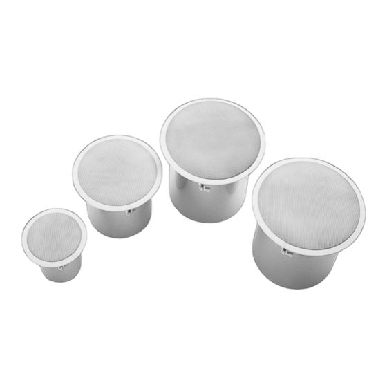
Page 6: System Overview
Features an easy 3-point mounting system for quick installations. EVID-C4.2LP The C4.2LP is the same as the C4.2 but in a low-profile installation package, ideal for tight ceiling spaces. -
Page 7: Packing List
Owner’s manual Support ring screws Terminal connector Service center card Cutout template Paint shield A (x2) B (x4) C (x2) D (x2) J (x2) F (x4) G (x2) Figure 3.1: EVID packing list Electro-Voice Installation manual 2018.09 | 11 | F.01U.177.705... -
Page 8: Product Feature Identification
Grille safety tether hole Removable input terminal connector Tap selector Terminal cover latch Rotating mounting tabs Steel back can Terminal cover locking screw Seismic tab (auxiliary support ring) Strain relief fitting Grille safety tether 2018.09 | 11 | F.01U.177.705 Installation manual Electro-Voice... - Page 9 RR-42-B Rough-in plate for new construction involving the EVID C4.2 (package of 4) RR-82 Rough-in plate for new construction involving the EVID-C4.2LP, EVID-C6.2, C8.2, and C8.2LP (package of 4) RR-810 Rough-in plate for new construction involving the EVID C8.2HC and C10.1 (package...
-
Page 10: Installation And Wiring
After the sheetrock is installed the speaker can be wired up and mounted all from below the ceiling. 2018.09 | 11 | F.01U.177.705 Installation manual Electro-Voice... -
Page 11: Step 1 - Cut The Hole
C-ring and align the rails so that the ends extend OVER the T-channel grid on the side of the tile. Secure the rails onto the C-ring tabs by inserting a screw though each tab into the rail. Figure 4.4: Secure rails to C-Ring Electro-Voice Installation manual 2018.09 | 11 | F.01U.177.705... -
Page 12: Step 3 - Attach Wiring To The Terminal Connector
There are two possible layouts for wiring a group of speakers; wiring in parallel or Daisy- Chaining. Wiring in parallel Connect the wire pair of the subsequent speaker to pins 2 and 3. When one input connector is removed, subsequent speakers will remain connected. 2018.09 | 11 | F.01U.177.705 Installation manual Electro-Voice... - Page 13 C10.1 subwoofer should be reversed. C10.1 Subwoofer C4.2 Loudspeaker C4.2LP Loudspeaker Figure 4.8: Subwoofer polarity with C4.2/C4.2LP C6.2 Loudspeaker C10.1 Subwoofer C8.2/C8.2HC/C8.2LP Loudspeaker Figure 4.9: Subwoofer polarity with C6.2 or C8.2/C8.2HC/C8.2LP Electro-Voice Installation manual 2018.09 | 11 | F.01U.177.705...
-
Page 14: Step 4 - Secure The Cable To The Speaker
Input connector (A) Figure 4.10: Plug connector into socket for the C4.2LP Reinstalling the terminal cover plate for the EVID-C4.2LP To reinstall the terminal cover plate, do the following: Thread the wire through the strain relief fitting on the terminal cover plate. -
Page 15: Step 5 - Mount The Speaker Into The Ceiling
Please note that the first clockwise quarter-turn rotates the attachment tabs outward. The remaining turns tighten the tabs down onto the back of the ceiling surface. Electro-Voice Installation manual 2018.09 | 11 | F.01U.177.705... -
Page 16: Step 6 - Connect An Auxiliary Support Line
Construction codes often require the use of this secondary support point. Caution! Ceiling mount speaker’s safety cable The safety cable should be installed with 1-3 inches (25.4-76.2 mm) of slack. 2018.09 | 11 | F.01U.177.705 Installation manual Electro-Voice... -
Page 17: Step 7 - Adjust Tap Selector
Second, press the grille into place until the front of the grille is flush with the rim of the baffle. Make sure the grille is securely seated to prevent it from vibrating loose. Electro-Voice Installation manual 2018.09 | 11 | F.01U.177.705... - Page 18 Continue the same procedure around the perimeter of the grille, loosening a portion at a time until the grille is removed. Figure 4.17: Attach the grille 2018.09 | 11 | F.01U.177.705 Installation manual Electro-Voice...
-
Page 19: Troubleshooting
Which ever condition results in greater low-frequency output is the in- polarity condition. If these suggestions do not solve your problem, contact your nearest Electro-Voice dealer or Electro-Voice distributor. Electro-Voice Installation manual 2018.09 | 11 | F.01U.177.705... -
Page 20: Technical Data
| Technical data EVID Ceiling Speaker Systems Technical data EVID C4.2 and EVID-C4.2LP Specification EVID C4.2 C4.2LP Frequency response 65 Hz - 20 kHz 60 Hz - 20 kHz Sensitivity (SPL 1 W/1 m) 86 dB Coverage pattern 130° conical Power handling (@ 8Ω) - Page 21 1.8 (70V only)/3.7/7.5/15/30 W 7.5 (70V only)/15/30/60 W LF transducer 8 in (205 mm) high-compliance driver (weatherized cone) HF transducer 1 in (25 mm) Ti-coated dome Mounting system Integrated 4-point toggle anchors Electro-Voice Installation manual 2018.09 | 11 | F.01U.177.705...
- Page 22 Cutout dimensions (diam.) 12.6 in (320 mm) Dimensions (depth x diam.) 11.9 in x 13.8 in (303 mm x 351 mm) Net weight 15.5 lb (7.0 kg) Included accessories Tile bridge, mounting ring 2018.09 | 11 | F.01U.177.705 Installation manual Electro-Voice...
- Page 23 EVID Ceiling Speaker Systems Technical data | en Specification EVID C10.1 Safety agency ratings: UL 1480 Safe for use in air handling spaces per UL 2043 Electro-Voice Installation manual 2018.09 | 11 | F.01U.177.705...
-
Page 24: Appendices
Specific EVID Ceiling Series models accommodate each job, depending on how these criteria are specified. – Room size – Coverage density desired – Coverage angle specification of the speaker – Ceiling height – Audio program material being played 2018.09 | 11 | F.01U.177.705 Installation manual Electro-Voice... -
Page 25: Ceiling Systems: Size Vs. Coverage
8-inch unit (shown in angle B). When specifying a new system, you can take advantage of the C4.2’s wider dispersion to decrease the number of speakers required to cover a given area. This will result in even greater savings. Electro-Voice Installation manual 2018.09 | 11 | F.01U.177.705... - Page 26 EVID models assuming a 4-foot listening plane height. Using these figures you can lay out a coverage pattern for the job after deciding the overlap criteria. Model C4.2 C4.2LP C6.2 14.25' 28.5' 56.5' 2018.09 | 11 | F.01U.177.705 Installation manual Electro-Voice...
-
Page 27: Use Of Subwoofers
In such a space, position the subwoofers evenly throughout the room and a few feet from the wall or corners. The added loading of the walls will enhance the response in these larger areas. Electro-Voice Installation manual 2018.09 | 11 | F.01U.177.705... - Page 28 Bosch Sicherheitssysteme GmbH Bosch Security Systems, Inc Robert-Bosch-Ring 5 12000 Portland Avenue South 85630 Grasbrunn Burnsville MN 55337 Germany www.boschsecurity.com www.electrovoice.com © Bosch Sicherheitssysteme GmbH, 2018...