
Related Manuals for ASROCK NUC BOX-1165G7


Summary of Contents for ASROCK NUC BOX-1165G7
- Page 1 NUC BOX-1165G7 NUC BOX-1135G7 NUC BOX-1115G4 NUC BOX-6305E User Manual Version 1.0 Published March 2021...
- Page 2 (including damages for loss of profits, loss of business, loss of data, interruption of business and the like), even if ASRock has been advised of the possibility of such damages arising from any defect or error in the documentation or product.
- Page 3 DISPOSE OF USED BATTERIES ACCORDING TO THE INSTRUCTIONS Contact Information If you need to contact ASRock or want to know more about ASRock, you’re welcome to visit ASRock’s website at www.ASRock.com; or you may contact your dealer for further information.
-
Page 4: Table Of Contents
Contents Chapter 1 Introduction Package Contents Product Specifications Chapter 2 Product Overview Front View Rear View Inside View Chapter 3 Hardware Installation How to Remove the Bottom Case How to Install the WiFi Module How to Remove the M.2 SSD and the Bracket How to Install the M.2 SSD How to Install the 2.5-inch Hard Drive How to Install the Memory Modules (DDR4) - Page 5 5.1.1 UEFI Menu Bar 5.1.2 Navigation Keys Main Screen Advanced Screen 5.3.1 CPU Configuration 5.3.2 Chipset Configuration 5.3.3 Storage Configuration 5.3.4 Super IO Configuration 5.3.5 ACPI Configuration 5.3.6 USB Configuration 5.3.7 Trusted Computing Hardware Health Event Monitoring Screen Security Screen Boot Screen Exit Screen Chapter 6 Software Support...
-
Page 6: Chapter 1 Introduction
NUC 1100 BOX Series Chapter 1 Introduction Because the hardware specifications might be updated, the content of this documentation will be subject to change without notice. 1.1 Package Contents • NUC 1100 BOX Series • NUC 1100 BOX Series (pre-installed motherboard) •... -
Page 7: Product Specifications
1.2 Product Specifications NUC 1100 BOX Barebone Series NUC BOX-1165G7 (I7-1165G7, QC, Max Speed up to 4.7GHz) NUC BOX-1135G7 (I5-1135G7, QC, Max Speed up to 4.2GHz) NUC BOX-1115G4 (I3-1115G4, DC, Max Speed up to 4.1GHz) NUC BOX-6305E (Celeron 6305E, DC, 1.8GHz) - Page 8 NUC 1100 BOX Series Power Unit 19V/90W Adapter Dimension 110.mm (W)x 117.5mm (D) x 47.85mm (H) VESA Bracket included , supports 75 x 75 and 100 x 100 mm Volume 0.6L (Liters) Operating 0°C~40°C Temperature * For NUC 1100 BOX Series, it is not recommended to install 2.5” HDD. If you install the 2.5” HDD, please keep the NUC 1100 BOX Series in a vertical position to ensure better cooling performance.
-
Page 9: Chapter 2 Product Overview
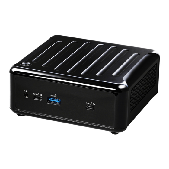
Chapter 2 Product Overview This chapter provides diagrams showing the location of important components of the NUC 1100 BOX Series. 2.1 Front View Description Audio(Mic-in, Line-out) 2 x USB 3.2 Gen2 Ports (Type C, supports DP1.2a display output) USB 3.2 Gen2 (Type A) -
Page 10: Rear View
NUC 1100 BOX Series 2.2 Rear View Description DC-IN HDMI RJ-45 (1G)* 2 x USB3.2 Gen2 Ports DisplayPort RJ-45 (2.5G)** * There are two LEDs on the LAN port. Please refer to the table below for the LAN port LED indications. ACT/LINK LED SPEED LED LAN Port... - Page 11 * There are two LEDs on the LAN port. Please refer to the table below for the LAN port LED indications. ACT/LINK LED SPEED LED LAN Port Activity / Link LED Speed LED Status Description Status Description No Link 10Mbps connection Blinking Data Activity Orange...
-
Page 12: Inside View
NUC 1100 BOX Series 2.3 Inside View Description SO-DIMM Slot SATA 3.0 Connector Mini PCIe Slot M.2 Slot Hard disk drive tray (compatible with 2.5" SATA HDD/SSD) SO-DIMM memory, hard drive and mSATA SSD are not included with this system. -
Page 13: Chapter 3 Hardware Installation
Chapter 3 Hardware Installation This chapter helps you install or remove important components. 3.1 How to Remove the Bottom Case 1. Remove the four screws on the bottom case. 2. Then lift up and remove the bottom panel.. -
Page 14: How To Install The Wifi Module
NUC 1100 BOX Series 3.2 How to Install the WiFi Module 1. Locate the WiFi Module slot on the motherboard. 2. Carefully insert the WiFi Module into the slot. 3. Tighten the screw to secure the WiFi Module to the motherboard. -
Page 15: How To Remove The M.2 Ssd And The Bracket
3.3 How to Remove the M.2 SSD and the Bracket 1. Release the screw and carefully remove the M.2 SSD. 2. Release the screw and remove the bracket from the motherboard. -
Page 16: How To Install The M.2 Ssd
NUC 1100 BOX Series 3.4 How to Install the M.2 SSD 1. Locate the M.2 slot on the motherboard. 2. Carefully insert the M.2 SSD into the slot. 3. Tighten the screw to secure the M.2 SSD to the motherboard. -
Page 17: How To Install The 2.5-Inch Hard Drive
3.5 How to Install the 2.5-inch Hard Drive 1. Remove the four screws on the bottom case. Then lift up and remove the bottom panel. 2. Attach the HDD to the hard drive mounting bracket and secure it using the four screws. - Page 18 NUC 1100 BOX Series 3. Connect the SATA Data and Power Cable to the HDD. 4. Connect the SATA Data and Power Cable to the HDD.
- Page 19 5. Connect the SATA Cable to the connector. 6. Then reinstall the bottom panel.
-
Page 20: How To Install The Memory Modules (Ddr4)
NUC 1100 BOX Series 3.6 How to Install the Memory Modules (DDR4) 1. The NUC 1100 BOX Series requires DDR4 SO-DIMM. 2. For dual channel configuration, you always need to install identical (the same brand, speed, size and chip-type) DDR4 SO-DIMM pairs. The SO-DIMM only fits in one correct orientation. -
Page 21: Chapter 4 Motherboard
Chapter 4 Motherboard 4.1 Motherboard Layout 1 : M.2 Key-M Socket (M2_M1) 2 : M.2 Key-E Socket (M2_E1) 3 : USB2.0 Connector (USB2_7_8) 4 : COM Port Header (RS232) 5 : Clear CMOS Header (CLRCMOS1) 6 : SATA3 Port (SATA3_0) 7 : SIO_AT1 8 : System Panel Header (PANEL1) Back Side :... -
Page 22: Motherboard Specifications
NUC 1100 BOX Series 4.2 Motherboard Specifications Form Dimensions NUC 4.09" x 4.02" (104 x 102mm) Factor ® Intel 11th Gen (Tiger Lake-UP3) Core™ Processors Processor I7-1185G7E QC, Max Speed up to 4.4GHz System Chipset BIOS AMI SPI 256 Mbit ®... - Page 23 1 x M.2 (KEY M, 2242/2260/2280) with PCIe Gen4 x4 and SATA3 for SSD Storage *M.2 Key M 2280(Supported by bracket) SATA 1 x SATA3.0 (6.0 Gb/s) Input PWR 12V~19V DC-In Jack AT/ATX Supported Power AT: Directly PWR on as power input ready Requirements Power On ATX: Press button to PWR on after power...
-
Page 24: Jumpers Setup
NUC 1100 BOX Series 4.3 Jumpers Setup The illustration shows how jumpers are setup. When the jumper cap is placed on pins, the jumper is “Short”. If no jumper cap is placed on pins, the jumper is “Open”. The illustration shows a 3-pin jumper whose pin1 and pin2 are “Short”... -
Page 25: Onboard Headers And Connectors
4.4 Onboard Headers and Connectors Onboard headers and connectors are NOT jumpers. Do NOT place jumper caps over these headers and connectors. Placing jumper caps over the headers and connectors will cause permanent damage of the motherboard! SATA3 Connector This Serial ATA3 (SATA3) connector supports SATA data (SATA3_0: see p.8, No. - Page 26 NUC 1100 BOX Series PLED (System Power LED): Connect to the power status indicator on the chassis front panel. The LED is on when the system is operating. The LED keeps blinking when the sys- tem is in S1 sleep state. The LED is off when the system is in S4 sleep state or powered off (S5).
- Page 27 Back Side: Power Button Header (PWR_BTN1) Fan Connector +12V (FAN1) FAN_SPEED FAN_SPEED_CONTROL Battery Connector (BAT1) ESPI Connector (ESPI1)
-
Page 28: Expansion Slots (M.2 Slots)
NUC 1100 BOX Series 4.5 Expansion Slots (M.2 Slots) There are 2 M.2 slots on this motherboard. M.2 for SSD: 1 x M.2 (KEY M, 2242/2260/2280) with PCIe Gen4 x4 and SATA3 for SSD. * M.2 Key M 2280(Supported by bracket) M.2 for Wi-Fi: 1 x M.2 (Key E, 2230) with PCIe x1, USB 2.0 and CNVi for Wireless. -
Page 29: Chapter 5 Uefi Setup Utility
Chapter 5 UEFI Setup Utility 5.1 Introduction This section explains how to use the UEFI SETUP UTILITY to configure your system. The UEFI chip on the motherboard stores the UEFI SETUP UTILITY. You may run the UEFI SETUP UTILITY when you start up the computer. Please press <F2>... -
Page 30: Navigation Keys
NUC 1100 BOX Series 5.1.2 Navigation Keys Please check the following table for the function description of each navigation key. Navigation Key(s) Function Description Moves cursor left or right to select Screens Moves cursor up or down to select items + / - To change option for the selected items <Enter>... -
Page 31: Advanced Screen
5.3 Advanced Screen In this section, you may set the configurations for the following items: CPU Configu- ration, Chipset Configuration, Storage Configuration, Super IO Configuration, ACPI Configuration, USB Configuration and Trusted Computing. Setting wrong values in this section may cause the system to malfunction. -
Page 32: Cpu Configuration
NUC 1100 BOX Series 5.3.1 CPU Configuration Intel Hyper Threading Technology To enable this feature, a computer system with an Intel processor that sup- ports Hyper-Threading technology and an operating system that includes ® ® optimization for this technology, such as Microsoft Windows 10 64-bit / 8.1 ®... - Page 33 Please note that enabling this function may reduce CPU voltage and lead to system stability or compatibility issues with some power supplies. Please set this item to [Disabled] if above issues occur. Intel Turbo Boost Technology Use this item to enable or disable Intel Turbo Boost Mode Technology. Turbo Boost Mode allows processor cores to run faster than marked fre- quency in specific conditions.
-
Page 34: Chipset Configuration
NUC 1100 BOX Series 5.3.2 Chipset Configuration VT-d ® ® Use this to enable or disable Intel VT-d technology (Intel Virtualization Technology for Directed I/O). The default value of this feature is [Disabled]. Share Memory Configure the size of memory that is allocated to the integrated graphics processor when the system boots up. -
Page 35: Storage Configuration
5.3.3 Storage Configuration SATA Controller(s) Use this item to enable or disable the SATA Controller feature. SATA Mode Selection Use this to select SATA mode. The default value is [AHCI Mode]. AHCI (Advanced Host Controller Interface) supports NCQ and other new features that will improve SATA disk perfor- mance but IDE mode does not have these advantages. -
Page 36: Super Io Configuration
NUC 1100 BOX Series 5.3.4 Super IO Configuration COM1 Configuration Use this to set parameters of COM1. WDT Timeout Reset Use this to set the Watch Dog Timer. -
Page 37: Acpi Configuration
5.3.5 ACPI Configuration Suspend to RAM Use this item to select whether to auto-detect or disable the Suspend-to- RAM feature. Select [Auto] will enable this feature if the OS supports it. Onboard LAN Power On Use this item to enable or disable onboard LAN to turn on the system from the power-soft-off mode. -
Page 38: Usb Configuration
NUC 1100 BOX Series 5.3.6 USB Configuration Legacy USB Support Enable or disable Legacy OS Support for USB 2.0 devices. If you encoun- ter USB compatibility issues it is recommended to disable legacy USB support. Select UEFI Setup Only to support USB devices under the UEFI setup and Windows/Linux operating systems only. -
Page 39: Trusted Computing
5.3.7 Trusted Computing Security Device Support Enable or disable BIOS support for security device. -
Page 40: Hardware Health Event Monitoring Screen
NUC 1100 BOX Series 5.4 Hardware Health Event Monitoring Screen In this section, it allows you to monitor the status of the hardware on your system, including the parameters of the CPU temperature, motherboard temperature, CPU fan speed, chassis fan speed, and the critical voltage. FAN1 Setting This allows you to set FAN1’s speed. -
Page 41: Security Screen
5.5 Security Screen In this section, you may set, change or clear the supervisor/user password for the system. Supervisor Password Set or change the password for the administrator account. Only the ad- ministrator has authority to change the settings in the UEFI Setup Utility. Leave it blank and press enter to remove the password. -
Page 42: Boot Screen
NUC 1100 BOX Series 5.6 Boot Screen In this section, it will display the available devices on your system for you to config- ure the boot settings and the boot priority. Boot From Onboard LAN Use this item to enable or disable the Boot From Onboard LAN feature. Setup Prompt Timeout This shows the number of seconds to wait for setup activation key. -
Page 43: Exit Screen
5.7 Exit Screen Save Changes and Exit When you select this option, it will pop-out the following message, “Save configuration changes and exit setup?” Select [OK] to save the changes and exit the UEFI SETUP UTILITY. Discard Changes and Exit When you select this option, it will pop-out the following message, “Discard changes and exit setup?”... -
Page 44: Chapter 6 Software Support
NUC 1100 BOX Series Chapter 6 Software Support 6.1 Install Operating System ® ® This motherboard supports various Microsoft Windows operating systems: 10 64-bit. Because motherboard settings and hardware options vary, use the setup procedures in this chapter for general reference only. Refer your OS documentation for more information.