Table of Contents
Advertisement
Quick Links
Advertisement
Table of Contents

Related Manuals for LG RT-44NZ31RB


Summary of Contents for LG RT-44NZ31RB
- Page 1 COLOR TV SERVICE MANUAL CHASSIS : MP-02AC MODEL : RT-44NZ31RB CAUTION BEFORE SERVICING THE CHASSIS, READ THE SAFETY PRECAUTIONS IN THIS MANUAL. TV/AV MENU INDEX...
-
Page 2: Table Of Contents
CONTENTS CONTENTS ...................... 2 SAFETY PRECAUTIONS ..................3 SERVICING PRECAUTIONS ................4 SPECIFICATIONS .................... 6 CONTROL DESCRIPTIONS................9 ADJUSTMENT INSTRUCTIONS..............12 TROUBLE SHOOTING..................21 PRINTED CIRCUIT BOARD................30 BLOCK DIAGRAM ..................39 EXPLODED VIEW ..................46 EXPLODED VIEW PARTS LIST..............47 REPLACEMENT PARTS LIST ..............48 SVC. -
Page 3: Safety Precautions
SAFETY PRECAUTIONS IMPORT ANT SAFETY NOTICE Many electrical and mechanical parts in this chassis have special safety-related characteristics. These parts are identified by the Schematic Diagram and Replacement Parts List. It is essential that these special safety parts should be replaced with the same components as recommended in this manual to prevent X-RADIATION, Shock, Fire, or other Hazards. -
Page 4: Servicing Precautions
SERVICING PRECAUTIONS CAUTION: Before servicing receivers covered by this service transistors and semiconductor "chip" components. The manual and its supplements and addenda, read and follow the following techniques should be used to help reduce the SAFETY PRECAUTIONS on page 3 of this publication. incidence of component damage caused by static by static NOTE: If unforeseen circumstances create conflict between the electricity. - Page 5 c. Quickly move the soldering iron tip to the junction of the Fuse and Conventional Resistor component lead and the printed circuit foil, and hold it Removal/Replacement there only until the solder flows onto and around both the 1. Clip each fuse or resistor lead at top of the circuit board component lead and the foil.
-
Page 6: Specifications
NOTE : Specifications and others are subject to change without notice for improvement. Scope Test and Inspection Method This specification can be applied to all the Projection television 1) performance:Follow the Standard of LG TV test related to MP-02AC Chassis. 2) Standards of Etc requirement Remark... - Page 7 Feature and Special SPEC Item Specification Remark PAL,SECAM-BG Feature RF Input PAL,SECAM-DK,PAL-IIÕ NTSC-M Rear2, Side1 (CVBS, L, R) Input 1, 2, 3 AV Input/Out Rear (CVBS,L,R) AV Out Rear,Side(Y,C) S-video S-video Rear 480i, 576i Component1 Y,Pb,Pr Input Rear 480i,576i,480P,576P,720P,1080I Component2 Rear, D-Sub 15pin PC(~SXGA)/DTV RGB Input...
- Page 8 Item Specification Remark TV, AV 1/2/3, Component 1/2, Scart (Option) RGB - PC, RGB - DTV, Scart RGB-PC(Option) TV, AV 1/2/3, Scart(AV4) Available Main Scart (Option) Sub Picture Picture 44,49 Inch (16:9), 44/49/54 Inch (4:3) Size _NA=4:3, NZ=16:9 768P @ 60Hz Display format NTSC,PC 625P @ 75Hz...
-
Page 9: Control Descriptions
MENU MUTE 9. SLEEP sets the sleep timer. 10. I/II selects the language during dual language broadcast. selects the sound output (option). 11. VCR BUTTONS control a LG video cassette recorder. POSITION SCAN STILL SIZE SLEEP LI ST I/II Q.VIEW... - Page 10 12. MULTIMEDIA POWER selects modes. Component 1, Component 2 or RGB-DTV TV/AV MULTIMEDIA 13. TURBO PICTURE BUTTON TURBO selects Turbo picture. SOUND PICTURE 14. TELETEXT BUTTONS (option) These buttons are used for teletext. For further details, see the ÔTeletextÕ section. 15.
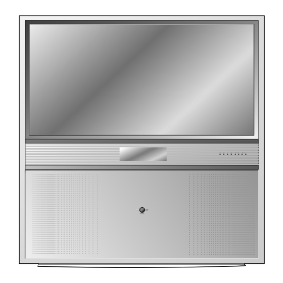
- Page 11 Front panel ¥ RT-44NZ31 series TV/AV MENU INDEX (Side panel) TV/AV MENU INDEX 1. MAIN POWER 8. INDEX switches the set on or off. switches LED DISPLAY on or off. 2. REMOTE CONTROL SENSOR (Volume Up/Down) adjusts the volume. 3. LED (Light Emitting Diode) DISPLAY adjusts menu settings.
-
Page 12: Adjustment Instructions
ADJUSTMENT INSTRUCTIONS Raster Slope/Focus 1th Adjustment 2. Preparation 1) Heat run over 60 minutes. 1. Preliminary steps 2) Pre-adjust Raster slope,Raster position,Lens focus ¢ering Magnet. 1) Turn on the power. 3) Verify that the Magnet is located 45mm from the end of PRT. 2) Receive the EU 05 CH signal. - Page 13 Centering Magnet Adjustment signal,and PAL adjustment should be done in standard mode of picture after receiving EU05 CH. 3) Press ÒIN-STARTÓ key on the adjustment remote controller 1. Preliminary steps and select Ò0.DEFLECTIONÓ 1) Tune the TV set to receive a EU 05 CH. 4) Display only the Green raster using lens covers to block Red (No PR.1:PAL B/G 175.25MHz) and Blue.
- Page 14 11) AFC ANG (Vertical slope adjustment) 6) Rotating lens right from the front side chromatic haze occurs Adjust the slope of screen to be vertical. beside Cross-hatch line changes as follows; Lens Change of chromatic aberration 12) AFC BOW (Vertical get bending adjustment) Adjust the slope to be parallel when the vertical slope get Orange ¤AScarlet banded.
- Page 15 4) Quit pattern shift mode. (Press ÒENTERÓ key) 5. Focus checking 5) Save adjusted phase/pattern position data After adjustment Red,Green & Blue lens, remove lens cover (Press Ò9Ó, Ò2Ó & ÒENTERÓ key) and receive Cross-Hatch pattern and check the overall focus. If needed,repeat above.
- Page 16 White Balance Adjustment Auto-Convergence Check 1. Test Equipment 1. PAL Auto-Convergence Check Brightness meter(CA110) 1) Receive EU05 CH signal. 2) Change the magnetometer in magnetometer. 2. Adjustment 3) Press ÒIN-STARTÓ key on R/C for adjustment and press the 1) This adjustment must be operated when it finished screen Ò9.AUTO CONVÓ...
- Page 17 CXA2180, AD9883, Default DATA 1.CXA Default Data (Decimal Data) ITEM DATA ITEM DATA ITEM DATA ITEM DATA R-Drive G-ON ABL-MOD CR-OFFS G-Drive B-ON CTI-MOD AGING-W B-Drive DCOL GAMMA AGING-B R-Cutof EXT-SW LTI-MOD SYSTEM G-Cutof SHP-FO DPIC-LE Y-OFFSE B-CutOf BLK-BTM DC-TRAN VM-DLY S-BRIGH PRE-OVE...
- Page 18 SVC Adjustment mode & Initial data Convergence Adjustment Mode 1. White Balance adjustment data (IC:CXA2180) 0.AC POSITION READ : Distance data(After auto convergence measuring) Menu Description Range Default 1.Save to 50Hz/60Hz : Save (convergence adjustment data) Red Drive ItÕs same 9,1,OK. 2.Save Control data : Save (A phase adjustment data) Green Drive ItÕs same 9,2,OK.
- Page 19 OPTION Data Adjustment Range Default Range Description Default Description 1: With Teletext 200 PR 1: 200 Program(CHINA Only) 0:100P 0:Teletext off option3 TEXT 0: Without Teletext(CHINA) 0: 100 Program 1:Teletext on 1:200P BLUACK 1: With BLUE BACK 0:OFF 0: Without BLUE BACK 1:ON DUAL 1: Save Dual Sound Condition...
- Page 20 State Language Function Default 0:ENG Only English 1:EU 5EA English/German/French/Italy/Spanish 2:EU ETC Pol./Hungary/Czech/Russia/Eng 3:PARSI English/Parsi LANG 4:ARAB URDU English/French/Arab+Urdu 5:English+Hindi English/Hindi 6:English+I+M+V English/Indonesian/Malaysian/Vietnamese 7:English+THAI English/Thai 8:English+China English/China 0:West Europe English/French/Swedish/Czech/German/Spanish/Italian 1:East Europe Polish/French/Swedish/Czech/German/Slovenian/Italian/Rumanian option4 2:Turkey EU English/French/Swedish/Turkish/German/Spanish/Italian 3:EAST EU2 English/Hungarian/Serbian/Czech/German/Polish/Spanish/Italian/ Rumanian 4:Cyrillic 1 5:Cyrillic 2...
-
Page 21: Trouble Shooting
TROUBLE SHOOTING - 21 -... - Page 22 - 22 -...
- Page 23 - 23 -...
- Page 24 - 24 -...
- Page 25 - 25 -...
- Page 26 - 26 -...
- Page 27 - 27 -...
- Page 28 - 28 -...
- Page 29 MEMO - 29 -...
-
Page 30: Printed Circuit Board
PRINTED CIRCUIT BOARD MAIN - 30 -... - Page 31 COMPONENT LOCATION GUIDE(MAIN) C010 C163..C3 C560..E4 IC503..E5 R019 ..F2 R128..A1 R565 ..F4 R665..C4 C011 C166..A1 C561..E4 IC504..D4 R020 ..F2 R131..C1 R566 ..F4 R666..C4 C012 C167..D3 C562..D4 IC505 ..F4 R021..E2 R134..C1 R567 ..F3 R670..E5 C014 C168..C3 C563..D3 IC601..D5 R022 ..F1 R135..C1 R568 ..F3 SM501A..F4 C015...
- Page 32 MAIN2 - 32 -...
- Page 33 A/V (TOP) - 33 -...
- Page 34 A/V (BOTTOM) - 34 -...
- Page 35 DIGITAL(TOP) DIGITAL(BOTTOM) - 35 -...
- Page 36 D-CON - 36 -...
- Page 37 CONT LED CVG OUT - 37 -...
- Page 38 CONT KEY POWER S/W SIDE A/V CVG INTERFACE PRI AMP - 38 -...
-
Page 39: Block Diagram
BLOCK DIAGRAM MAIN - 39 -... - Page 40 BLOCK DIAGRAM VIDEO IN/ OUT PART - 40 -...
- Page 41 BLOCK DIAGRAM COMPONENT & RGB SW Part - 41 -...
- Page 42 BLOCK DIAGRAM DPTV Input Part - 42 -...
- Page 43 BLOCK DIAGRAM Back-End Part - 43 -...
- Page 44 BLOCK DIAGRAM Sound Part - 44 -...
- Page 45 MEMO - 45 -...
-
Page 46: Exploded View
EXPLODED VIEW - 46 -... -
Page 47: Exploded View Parts List
Part No. Description 3680V00048B LENS, SEKINOS SSM-100(50) LENS ASSEMBLY 4810V00675U BRACKET, PRT ASSY RT-44NZ31RB MP02AC GLASS RED FOR SET 4810V00675V BRACKET, PRT ASSY RT-44NZ31RB MP02AC GLASS GREEN FOR SET 4810V00675W BRACKET, PRT ASSY RT-44NZ31RB MP02AC GLASS BLUE FOR SET 120-D38E... -
Page 48: Replacement Parts List
REPLACEMENT PARTS LIST LOCA. NO PART NO DESCRIPTION LOCA. NO PART NO DESCRIPTION IC209 0IMMRSS037E K4S643232H-TC60 TRAY 64M SDRAM(2M*32) IC209 0IMCRFA008A KA78M05RTM, 2P D-PAK, R/TP REGULATOR IC IC001 0ISM555000A SDA5550 MQFP100 BK MICOM TXT MC006A IC210 0IPRPFA006A RC1117S33T SOT-223 3.3VOLT REGULATOR IC002 0IKE781200F KIA78L12BP(AT) 3P 12V,150MA... - Page 49 LOCA. NO PART NO DESCRIPTION LOCA. NO PART NO DESCRIPTION Q2202 0TR150400BA CHIP 2SA1504S(ASY) KEC TRANSISTOR Q2203 0TR387500AA CHIP 2SC3875S(ALY) KEC D401 0TFSG10004A STW20NK50Z SGS-T(STM) ST TO-247 500V 17A Q2204 0TR387500AA CHIP 2SC3875S(ALY) KEC IC008 0TR830009BA BSS83 TP NON N-CHANNEL S/W TR Q2205 0TR387500AA CHIP 2SC3875S(ALY) KEC...
- Page 50 LOCA. NO PART NO DESCRIPTION LOCA. NO PART NO DESCRIPTION Q520 0TR387500AA 0TR319809AA CHIP 2SC3875S(ALY) KEC KTC3198(KTC1815) KEC TP TO92 50V 150MA Q521 0TR387500AA 0TR319809AA KTC3198(KTC1815) KEC TP TO92 50V 150MA CHIP 2SC3875S(ALY) KEC Q601 0TR387500AA CHIP 2SC3875S(ALY) KEC 0TR319809AA KTC3198(KTC1815) KEC TP TO92 50V 150MA Q602 0TR387500AA...
- Page 51 For Capacitor & Resistors, CC, CX, CK, CN : Ceramic RD : Carbon Film the charactors at 2nd and 3rd CQ : Polyestor RS : Metal Oxide Film digit in the P/No. means as CE : Electrolytic RN : Metal Film follows;...
- Page 52 For Capacitor & Resistors, CC, CX, CK, CN : Ceramic RD : Carbon Film the charactors at 2nd and 3rd CQ : Polyestor RS : Metal Oxide Film digit in the P/No. means as CE : Electrolytic RN : Metal Film follows;...
- Page 53 For Capacitor & Resistors, CC, CX, CK, CN : Ceramic RD : Carbon Film the charactors at 2nd and 3rd CQ : Polyestor RS : Metal Oxide Film digit in the P/No. means as CE : Electrolytic RN : Metal Film follows;...
- Page 54 For Capacitor & Resistors, CC, CX, CK, CN : Ceramic RD : Carbon Film the charactors at 2nd and 3rd CQ : Polyestor RS : Metal Oxide Film digit in the P/No. means as CE : Electrolytic RN : Metal Film follows;...
- Page 55 For Capacitor & Resistors, CC, CX, CK, CN : Ceramic RD : Carbon Film the charactors at 2nd and 3rd CQ : Polyestor RS : Metal Oxide Film digit in the P/No. means as CE : Electrolytic RN : Metal Film follows;...
- Page 56 100UF STD 100V M FL TP5 T403 6170VMCA26E SMPS[COIL]EER2834 1200UH RT44NZ31RB C938 0CQ1031N509 0.01UF D 100V 10% PE TP5 T404 6170VMCA67A SMPS[COIL]EI-2820 1.25UH RT-44NZ31RB C939 0CK104DK56A 0.1UF 2012 50V 10% R/TP X7R T801 6170VMCB16F SMPS[COIL]EE5555 300UH RT-44NZ31RB C941 0CK4720W510 4700P 500V K B S...
- Page 57 For Capacitor & Resistors, CC, CX, CK, CN : Ceramic RD : Carbon Film the charactors at 2nd and 3rd CQ : Polyestor RS : Metal Oxide Film digit in the P/No. means as CE : Electrolytic RN : Metal Film follows;...
- Page 58 For Capacitor & Resistors, CC, CX, CK, CN : Ceramic RD : Carbon Film the charactors at 2nd and 3rd CQ : Polyestor RS : Metal Oxide Film digit in the P/No. means as CE : Electrolytic RN : Metal Film follows;...
- Page 59 For Capacitor & Resistors, CC, CX, CK, CN : Ceramic RD : Carbon Film the charactors at 2nd and 3rd CQ : Polyestor RS : Metal Oxide Film digit in the P/No. means as CE : Electrolytic RN : Metal Film follows;...
- Page 60 For Capacitor & Resistors, CC, CX, CK, CN : Ceramic RD : Carbon Film the charactors at 2nd and 3rd CQ : Polyestor RS : Metal Oxide Film digit in the P/No. means as CE : Electrolytic RN : Metal Film follows;...
- Page 61 SW801S 140-289A PUSH,POWER SDDF3PASP013 LG C&D UL/C RT19 0RD1500H609 150 OHM 1/2 W 5.00% TA52 SWT1 140-313B TACT,TACT 2LEAD 160G(TA) LG C&D NON 0RD4701F609 4.7K OHM 1/6 W 5% TA52 SWT2 140-313B TACT,TACT 2LEAD 160G(TA) LG C&D NON RT20 0RD1000F609...
- Page 62 LOCA. NO PART NO DESCRIPTION LOCA. NO PART NO DESCRIPTION FB410 125-022K L216 6210TCE001G FERRITE NON AXIAL 62MM 1UH NY 3.5X6.0MM HH-1M3216-501 CERATEC 3216MM R/TP FB411 125-022K L218 6210TCE001G HH-1M3216-501 CERATEC 3216MM R/TP FERRITE NON AXIAL 62MM 1UH NY 3.5X6.0MM FB801 125-022K FERRITE NON AXIAL 62MM 1UH NY 3.5X6.0MM...
- Page 63 LOCA. NO PART NO DESCRIPTION LOCA. NO PART NO DESCRIPTION SG903G 6918VAX002E WSP-351M 350V 20% AXIAL TP 7.5MM SG903R 6918VAX002E WSP-351M 350V 20% AXIAL TP 7.5MM ACCESSORIES 3828VA0467D MANUAL,OWNER SMP02AC AP 100R/U/Z TX 395A 6710V00100R REMOTE CONTROLLER, MP03AB FULL SPEC MISCELLANEOUS F800 0FS5001B51D...
- Page 64 3854VA0109G - S1(1/3) 04.04.22...
- Page 65 3854VA0109G - S1(2/3) 04.04.22...
- Page 66 3854VA0109G - S2(3/3) 04.04.22...
-
Page 67: Svc. Sheet
SVC. SHEET : 3854V A0109G-S1 3854V A0109G-S2... - Page 68 Apr., 2004 P/NO : 3828VD0192A Printed in Korea...