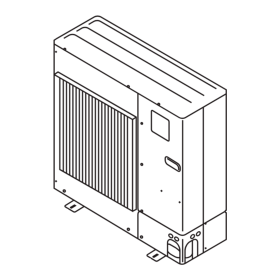
Mitsubishi Electric Mr. SLIM PUZ-A NHA3 Series Installation Manual
Hide thumbs
Also See for Mr. SLIM PUZ-A NHA3 Series:
- Installation manual (36 pages) ,
- Instruction manual (35 pages)
Table of Contents
Advertisement
Quick Links
Air-Conditioners
PUZ-A·NHA3, PUZ-A·NHA3-BS
PUZ-A·NHA4, PUZ-A·NHA4-BS
PUZ-A·NHA5, PUZ-A·NHA5-BS
PUY-A·NHA3, PUY-A·NHA3-BS
PUY-A·NHA4, PUY-A·NHA4-BS
PUY-A·NHA5, PUY-A·NHA5-BS
INSTALLATION MANUAL
For safe and correct use, read this manual and the indoor unit installation manual thoroughly before installing
the air-conditioner unit.
FOR INSTALLER
English
Français
Español
Advertisement
Table of Contents

Summary of Contents for Mitsubishi Electric Mr. SLIM PUZ-A NHA3 Series
- Page 1 Air-Conditioners PUZ-A·NHA3, PUZ-A·NHA3-BS PUZ-A·NHA4, PUZ-A·NHA4-BS PUZ-A·NHA5, PUZ-A·NHA5-BS PUY-A·NHA3, PUY-A·NHA3-BS PUY-A·NHA4, PUY-A·NHA4-BS PUY-A·NHA5, PUY-A·NHA5-BS INSTALLATION MANUAL FOR INSTALLER English For safe and correct use, read this manual and the indoor unit installation manual thoroughly before installing the air-conditioner unit. Français Español...
-
Page 2: Table Of Contents
• Use only accessories authorized by Mitsubishi Electric and ask a dealer or safety limit in the event of refrigerant leakage. Consult a dealer regarding an authorized technician to install them. If accessories are incorrectly in- the appropriate measures to prevent the allowable concentration from be- stalled, water leakage, electric shock, or fire may result. -
Page 3: Installation Location
1. Safety precautions 1.3. Before electric work Caution: • Be sure to install circuit breakers. If not installed, electric shock may result. • Be sure to ground the unit. Do not connect the ground wire to gas or water • For the power lines, use standard cables of sufficient capacity. Otherwise, a pipes, lighting rods, or telephone grounding lines. -
Page 4: Installing The Outdoor Unit
2. Installation location 2.4.2. When installing a single outdoor unit (Refer to the last page) Minimum dimensions are as follows, except for Max., meaning Maximum dimen- sions, indicated. The figures in parentheses are for A42 models. Refer to the figures for each case. Obstacles at rear only (Fig. -
Page 5: Installing The Refrigerant Piping
4. Installing the refrigerant piping 4.1. Precautions for devices that use R410A refrigerant • Refer to page 3 for precautions not included below on using air conditioners with R410A refrigerant. • Use ester oil, ether oil, alkylbenzene oil (small amount) as the refrigeration oil applied to the flared sections. - Page 6 4. Installing the refrigerant piping 4.4. Refrigerant pipe airtight testing method (1) Connect the testing tools. • Make sure the stop valves are closed and do not open them. • Add pressure to the refrigerant lines through the service port of the liquid stop valve (2) Do not add pressure to the specified pressure all at once;...
-
Page 7: Drainage Piping Work
4. Installing the refrigerant piping 4.7. For twin combination (For A24, A36 only) Refrigerant piping limitation of length, height difference are shown in the figure. (Fig. 4-8) Indoor unit Outdoor unit Multi distribution pipe (option) Height difference (Indoor unit-Outdoor unit) Max. 30 m, 100 ft Height difference (Indoor unit-Indoor unit) Max. - Page 8 A12, A18 CORD COVER S1 S2 S3 TERMINAL BED CONDUIT COVER CABLE STRAP SERVICE PANEL A24-A42 CONDUIT PLATE : accessory...
-
Page 9: Test Run
6. Electrical work 6.2. Field electrical wiring Outdoor unit model Outdoor unit power supply Single, 208/230 V, 60 Hz Single, 208/230 V, 60 Hz Single, 208/230 V, 60 Hz Single, 208/230 V, 60 Hz Single, 208/230 V, 60 Hz Single, 208/230 V, 60 Hz Breaker size 15 A 15 A... -
Page 10: Special Functions
7. Test run 7.2. Test run 7.2.1. Using SW4 in outdoor unit • After power is supplied, a small clicking noise may be heard from the inside of the outdoor unit. The electronic expansion valve is opening and closing. The unit 1) PUH Type, PUZ Type is not faulty. -
Page 11: System Control (Fig. 9-1)
9. System control (Fig. 9-1) SW 1 - 3 ~ 6 Outdoor unit Set the refrigerant address using the DIP switch of the outdoor unit. Indoor unit Wiring from the Remote Control Master remote controller This wire is connected to TB5 (terminal board for remote controller) of the indoor Subordinate remote controller unit (non-polar). - Page 12 inch Fig. 2-8 Fig. 2-7 Fig. 2-6 Fig. 2-11 Fig. 2-9 Fig. 2-10 Fig. 2-13 Fig. 2-12 Fig. 2-14 Fig. 2-15 Fig. 2-16 Fig. 2-18 Fig. 2-17...
- Page 13 This product is designed and intended for use in the residential, commercial and light-industrial environment. Please be sure to put the contact address/telephone number on this manual before handing it to the customer. HEAD OFFICE: TOKYO BLDG., 2-7-3, MARUNOUCHI, CHIYODA-KU, TOKYO 100-8310, JAPA P P N BG79U896H07 Printed in Japan...


