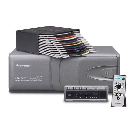
Pioneer CDX-FM1277 Service Manual
Universal multi-cd system
Hide thumbs
Also See for CDX-FM1277:
- Service manual (61 pages) ,
- Operation manual (52 pages) ,
- Installation manual (4 pages)
Table of Contents
Advertisement
Service
Manual
UNIVERSAL MULTI-CD SYSTEM
CDX-FM1277
CDX-FM1277
CDX-FM1279
- This service manual should be used together with the following manual(s):
Model No.
Order No.
CX-938
CRT2357
CONTENTS
1. SAFETY INFORMATION ............................................2
2. EXPLODED VIEWS AND PARTS LIST .......................3
4. PCB CONNECTION DIAGRAM ................................26
5. ELECTRICAL PARTS LIST ........................................34
6. ADJUSTMENT..........................................................38
PIONEER CORPORATION
PIONEER ELECTRONICS SERVICE INC.
PIONEER EUROPE NV
Haven 1087 Keetberglaan 1, 9120 Melsele, Belgium
PIONEER ELECTRONICS ASIACENTRE PTE.LTD. 253 Alexandra Road, #04-01, Singapore 159936
C PIONEER CORPORATION 2000
CDX-FM1277/X1N/UC
Mech. Module
Remarks
C8
CD Mech. Module:Circuit Description, Mech. Description, Disassembly
4-1, Meguro 1-Chome, Meguro-ku, Tokyo 153-8654, Japan
P.O.Box 1760, Long Beach, CA 90801-1760 U.S.A.
X1N/ES
X1N/UC
7. GENERAL INFORMATION .......................................48
7.1 DIAGNOSIS ........................................................48
7.1.1 TEST MODE ..............................................48
7.1.2 DISASSEMBLY .........................................52
7.2 PARTS .................................................................55
7.2.1 IC................................................................55
7.2.2 DISPLAY ....................................................57
7.3 OPERATIONAL FLOW CHART ...........................58
8. OPERATIONS AND SPECIFICATIONS.....................59
K-ZZY. DEC. 2000 Printed in Japan
ORDER NO.
CRT2590
X1N/UC
Advertisement
Table of Contents

Related Manuals for Pioneer CDX-FM1277

Summary of Contents for Pioneer CDX-FM1277
- Page 1 PIONEER CORPORATION 4-1, Meguro 1-Chome, Meguro-ku, Tokyo 153-8654, Japan PIONEER ELECTRONICS SERVICE INC. PIONEER EUROPE NV Haven 1087 Keetberglaan 1, 9120 Melsele, Belgium PIONEER ELECTRONICS ASIACENTRE PTE.LTD. 253 Alexandra Road, #04-01, Singapore 159936 C PIONEER CORPORATION 2000 CDX-FM1277/X1N/UC X1N/ES X1N/UC Remarks CD Mech.
-
Page 2: Safety Information
1. SAFETY INFORMATION - CDX-FM1277/X1N/UC and CDX-FM1279/X1N/UC CAUTION This service manual is intended for qualified service technicians; it is not meant for the casual do-it-yourselfer. Qualified technicians have the necessary test equipment and tools, and have been trained to properly and safely repair complex products such as those covered by this manual. -
Page 3: Exploded Views And Parts List
2. EXPLODED VIEWS AND PARTS LIST 2.1 PACKING CDX-FM1277,FM1279... - Page 4 33 Antenna Select Assy 34 Display Assy 35 Remote Control Assy 36 Magazine Assy 37 Angle Assy 38 Caution Card 39 Caution Card 40 Air Cushioned Bag 41 Cover Part No. CDX-FM1277/X1N/UC CDX-FM1279/X1N/UC CEA2767 CEA2767 CBH-865 CBH-865 CDE4289 CDE4289 CDE5812 CDE5812...
- Page 5 - Owner’s Manual Model CDX-FM1277/X1N/UC CDX-FM1279/X1N/UC CDX-FM1277/X1N/ES - Installation Manual Model CDX-FM1277/X1N/UC CDX-FM1279/X1N/UC CDX-FM1277/X1N/ES CDX-FM1277,FM1279 Part No. Language CRD3354 English, French CRD3355 English, French CRD3352 English, Spanish, Portuguese(B), Arabic Part No. Language CRD3356 English, French CRD3356 English, French CRD3353 English, Spanish, Portuguese(B), Arabic...
- Page 6 CDX-FM1277,FM1279 2.2 EXTERIOR...
- Page 7 26 Screw 27 Jack(CN401) 28 Plug(CN801) 29 Connector(CN802) 30 Connector(CN803) (2) CONTRAST TABLE CDX-FM1277/X1N/UC,CDX-FM1279/X1N/UC and CDX-FM1277/X1N/ES are constructed the same except for the following: Mark No. Symbol and Description 11 Upper Case 36 Display Assy 45 Grille Unit 46 Grille Assy...
- Page 8 CDX-FM1277,FM1279 2.3 CD MECHANISM MODULE...
- Page 9 83 Frame Unit CNC7921 84 Magazine Holder Unit CNC7922 CNC7923 CNC7924 87 Screw CNC7927 88 Motor Unit(M853)(TRAY) CXB4421 CNC7928 89 Screw CNC8355 90 Motor Unit(M852)(ELV) CDX-FM1277,FM1279 Part No. CNC8375 CNC8434 CNM6009 CNM6428 CNM6296 CNP5227 CNP5228 CNR1189 CNR1531 CNT1086 CNV5472 CNV5473...
- Page 10 CDX-FM1277,FM1279 Mark No. Description 91 Screw 92 Lever Unit 93 ••••• 94 Gear Unit 95 Screw 96 Pickup Unit(Service) 97 ••••• 98 ••••• 99 Screw 100 Screw 101 Photo-transistor(Q851) Spring Switch(S851,S853) 103 LED(D851) 104 Spring Switch(S852) Part No. JFZ20P025FMC CXB3938...
- Page 11 2.4 MAGAZINE ASSY - MAGAZINE ASSY SECTION PARTS LIST Mark No. Description 1 Magazine Assy 2 Tray 3 Label Part No. CXB4028 CNV5341 CRW1419...
-
Page 12: Block Diagram And Schematic Diagram
CDX-FM1277,FM1279 3. BLOCK DIAGRAM AND SCHEMATIC DIAGRAM 3.1 BLOCK DIAGRAM MECHANISM PICKUP UNIT (SERVICE) (P8) MONITOR DIODE HOLOGRAM UNIT LD(–) LASER DIODE FOCUS ACT. TRACKING ACT. CARRIAGE MOTOR SPINDLE MOTOR MOTOR PCB MOTOR SWITCH PCB HOME SW S853 DSPSW S852... - Page 13 7.2MHz 5V REGULATOR Q901 CN802 KYDT DPDT IC 901 KYDT DPDT PD6294A 1PADD1/LCH SWDACC CN901 X901 4.9152MHz DISPLAY ASSY CDX-FM1277,1279 ANTENNA SELECT UNIT CN401 RELAY CN501 RY501 Q403 Q404 CDRFIN LOUT L402 CTC1079 Q402 TP30 Q501 CN803 IP-BUS OUT LOUT...
-
Page 14: Cd Mechanism Module
CDX-FM1277,FM1279 3.2 CD MECHANISM MODULE Note: When ordering service parts, be sure to refer to “EXPLODED VIEWS AND PARTS LIST” or “ELECTRICAL PARTS LIST”. PICKUP UNIT(SERVICE) CXX1285 M854 CXB3004 M851 CXB3003 SWITCH PCB CN504-2 CSN1052 CSN1051 M853 CXB4421 MOTOR PCB... - Page 15 The > mark found on some component parts indicates the importance of the safety factor of the part. Therefore, when replacing, be sure to use parts of identical designation. CD CORE UNIT CDX-FM1277,1279 Decimal points for resistor and capacitor fixed values are expressed as : 0.022...
- Page 16 CDX-FM1277,FM1279 SYSTEM CONTROLLER...
- Page 17 SRAM IP-BUS DRIVER CDX-FM1277,1279...
- Page 18 CDX-FM1277,FM1279 - Waveforms 1 RFI 0.5V/div. 0.5µs/div. Normal mode: play REFO 3 CH1: FD 0.5V/div. 0.2s/div. 4 CH2: FOR 2V/div. Test mode: No disc, Focus close REFO REFO 8 CH1: TE 0.5V/div. 0.5ms/div. 9 CH2: TD 0.5V/div. Test mode: 32 tracks jump (REV)
- Page 19 Normal mode: Play REFO % SCKO 2V/div. 1µs/div. Normal mode: Play REFO * VD 5V/div. 50ms/div. Normal mode: No disc CDX-FM1277,FM1279 0 MD 0.5V/div. 0.1s/div. Normal mode: Play (12cm) REFO 8 CH1: TE 1V/div. 2ms/div. # CH2: TEC 1V/div. Test mode: Focus close...
- Page 20 CDX-FM1277,FM1279 ( CH1: R OUT 2V/div. 500µs/div. ) CH2: L OUT 2V/div. Normal mode: Play (1kHz 0dB) REFO REFO 1 CH1: RFI 1V/div. 0.5ms/div. ⁄ CH2: HOLD 5V/div. Normal mode: The defect part passes 800µm(B.D) REFO REFO 6 CH1: FE 0.2V/div.
- Page 21 CDX-FM1277,FM1279...
- Page 22 CDX-FM1277,FM1279 3.3 EXTENSION UNIT 19kHz LPF 6V REG. 3V REG. 5V REG. VD REGULATOR ADD ON MODE LOOP FILTER...
- Page 23 MAX AMP PILOT BUFFER AMP ILTER IP-BUS 8 9 10 11 1 2 3 4 CN901 FUSE 2A CEK1018 1K(1/2W) 33K (B) EXTENSION UNIT CDX-FM1277,1279 CN501...
- Page 24 CDX-FM1277,FM1279 3.4 ANTENNA SELECT UNIT CN401 ANTENNA SELECT UNIT TUNER ANTENNA...
- Page 25 3.5 DISPLAY ASSY CN802 CDX-FM1277,FM1279...
-
Page 26: Pcb Connection Diagram
CDX-FM1277,FM1279 4. PCB CONNECTION DIAGRAM 4.1 CD CORE UNIT NOTE FOR PCB DIAGRAMS 1. The parts mounted on this PCB include all necessary parts for several destination. For further information for respective destinations, be sure to check with the schematic dia- gram. - Page 27 CDX-FM1277,FM1279 SIDE B...
- Page 28 CDX-FM1277,FM1279 4.2 EXTENSION UNIT EXTENSION UNIT IC, Q ADJ CN901 CN701 CORD IP-BUS SIDE A CN501...
- Page 29 EXTENSION UNIT CDX-FM1277,FM1279 SIDE B IC, Q...
- Page 30 CDX-FM1277,FM1279 4.3 MECHANISM PCB MECHANISM PCB CN101 4.4 SWITCH PCB SWITCH PCB HOME D851 PICKUP UNIT M851 (SERVICE) SPDL M854...
- Page 31 4.5 MOTOR PCB MOTOR PCB 4.6 ANTENNA SELECT UNIT ANTENNA SELECT UNIT ANTENNA CN401 TUNER CDX-FM1277,FM1279...
- Page 32 CDX-FM1277,FM1279 4.7 DISPLAY ASSY SIDE A...
- Page 33 CDX-FM1277,FM1279 SIDE B...
-
Page 34: Electrical Parts List
CDX-FM1277,FM1279 5. ELECTRICAL PARTS LIST NOTE: - Parts whose parts numbers are omitted are subject to being not supplied. - The part numbers shown below indicate chip components. Chip Resistor RS1/_S___J,RS1/__S___J Chip Capacitor (except for CQS...) CKS..., CCS..., CSZS... =====Circuit Symbol and No.===Part Name... - Page 35 Ceramic Resonator 16.93MHz Radiator 10.00MHz CCSRCH271J50 CCSQCH162J50 Push Switch(EJECT) CEAL100M16 Push Switch(RESET) CCSRCH270J50 Spring Switch(MAG) CCSRCH270J50 Semi-fixed 680Ω(B) CKSRYB104K16 RESISTORS CKSRYB102K50 CKSRYB473K16 CEALNP330M10 CEAL470M6R3 CDX-FM1277,FM1279 Part No. ------------------------- CKSRYB104K16 CCSRCH180J50 CCSRCH100D50 CCSRCH330J50 CCSRCH180J50 CCSRCK1R0C50 CKSRYB103K50 CCSRCK1R0C50 CKSRYB103K50 CKSRYB103K50 CCSRCJ3R0C50 CKSRYB103K50 CKSRYB473K16 CEAL220M16...
- Page 36 CDX-FM1277,FM1279 =====Circuit Symbol and No.===Part Name ------ ------------------------------------------ =====Circuit Symbol and No.===Part Name Part No. ------ ------------------------------------------ ------------------------- RS1/16S393J RS1/16S182J RS1/16S103J RS1/16S103J RS1/16S123J RS1/16S681J RS1/16S681J RS1/16S681J RS1/16S681J RS1/16S681J RS1/16S102J RS1/16S681J RS1/16S681J RS1/16S103J RS1/16S153J RS1/16S103J RS1/16S103J RS1/16S103J RS1/16S752J RS1/16S103J RS1/16S752J RAB4C332J...
- Page 37 MA153 CSS1449 CSG1110 CSG1110 CSG1110 CSG1110 CSG1110 CSG1110 CSG1110 CEL1608 CEL1608 CAW1514 RS1/16S102J RS1/16S332J RS1/16S471J RS1/16S471J RS1/16S332J RS1/16S223J CDX-FM1277,FM1279 Part No. ------------------------- CKSRYB473K16 CSZSR100M16 CSZSR100M16 CKSRYB104K16 CKSRYB104K16 CKSRYB104K16 : Antenna Select Unit 2SC1740S 1SS133 LAU4R7K CSR1014 RD1/4PU683J RD1/4PU103J CKCYB102K50 CEAL101M10...
-
Page 38: Adjustment
CDX-FM1277,FM1279 6. ADJUSTMENT 6.1 CD ADJUSTMENT - Precautions • This unit uses a single power supply (+5V) for the reg- ulator. The signal reference potential, therefore, is connected to REFO(approx. 2.5V) instead of GND. If REFO and GND are connected to each other by mis-... - Page 39 • During exchanging discs, do not press the keys for the discs to be exchanged. CDX-FM1277,FM1279 • The following head units are exceptional so that their entering ways to the test mode are different from oth- ers.
- Page 40 CDX-FM1277,FM1279 - Flow Chart Test Mode In Sourse CD SOURCE BAND Power ON (Adjustment for T.Offset) (Not adjustment for T.Offset) 00 00 00 Display Display Power OFF BAND Focus Close/ S Curve Check 91 91 91 Display Display Power OFF BAND T.Close and...
- Page 41 6.2 CHECKING THE GRATING - Checking the Grating After Changing the Pickup Unit • Note : CD mechanism modules the grating angle of the pickup unit cannot be adjusted after the pickup unit is changed. The pickup unit in the CD mechanism module is adjusted on the production line to match the CD mechanism module and is thus the best adjusted pickup unit for the CD mechanism module.
- Page 42 Grating waveform 0˚ 45˚ 75˚ Echt Xch 20mV/div, AC Fcht Ych 20mV/div, AC 30˚ 60˚ 90˚...
- Page 43 EREF EPVO The amount of movement changes each time key 12 is pressed. maximum movement Key 12 during movement Key 12 Key 12 minimum movement CDX-FM1277,FM1279 Oscilloscope L.P.F. Examples of display TRACK FUNCTION " TRACK FUNCTION 00' 00" TRACK FUNCTION 00' 02"...
- Page 44 4. Press key 9 to set ELV/TRAY mode to TRAY. 5. Press key FF to release the clamp and return the tray to the magazine. 6. Press key 9 to enter Elevation Move mode. 7. Use key FF/REV to operate elevation and set if to the graduation of the sixth step (Fig.
- Page 45 17. Wait more than one minute after the power is turned off, then turn the power ON and insert a magazine. 18. Check if the mechanism operates correctly with the first, sixth, seventh and twelfth CDs. 19. If the mechanism operates properly, adjustment is completed. If the mechanism operates improperly, make the adjustment again. CDX-FM1277,FM1279 VR802 EREF L.P.F.
- Page 46 CDX-FM1277,FM1279 Adjust the insertion gate of magazine to the sixth scale. Fig. 1 Stopper bend of the clamp lever Engaged in the center and pressed downward. Dislocated toward the twelfth CD. Frame stopper Dislocated toward the first CD. Fig. 2 Fig.
- Page 47 6.4 MODULATOR ADJUSTMENT - Connection Diagram Antenna Jack Linear Detector (Spectrum Analyzer) FM Tuner DC V Meter VR301 CN201 EXTENSION UNIT - Adjustment CD Signal Tuning Voltage -∞ Adjustment Balance Adjustment -∞ Modulation 400Hz 0dB (*1) VR302 Adjustment 499Hz 0dB *1 : L and R are input at the same time.
-
Page 48: General Information
CDX-FM1277,FM1279 7. GENERAL INFORMATION 7.1 DIAGNOSIS 7.1.1 TEST MODE - Error Messages If a CD is not operative or stopped during operation due to an error, the error mode is turned on and cause(s) of the error is indicated with a corresponding number. This arrangement is intended at reducing nonsense calls from the users and also for facilitating trouble analysis and repair work in servicing. - Page 49 FWD-Kick REV-Kick T.Close (AGC performed) /parameter display switching Parameter display switching /T.BAL adjustment/T.Open F.Close/RF AGC/F.T.AGC F.Open Jump Off F.Mode switching /T.Close (no AGC)/Jump switching CDX-FM1277,FM1279 New test mode In-play Error Production – Time/Err.No. switching FF/TR+ – REV/TR- – Scan –...
- Page 50 CDX-FM1277,FM1279 Mechanism Test Mode (Example) BAND Back to the test mode Playing the mechanism DOWN Playing the mechanism Mechanism test mode in – TRAY/ELV select – – Operation step select Note: Eject and CD on/off is performed in the same procedure as that for the normal mode.
- Page 51 Off focus. Off focus. Off focus. Off focus. Off focus. Off focus. Off focus. Off focus. Off focus. Off focus. Off focus. Off focus. Off focus or spindle not locked. Off focus. Off focus. Off focus. SEC. 11" SEC. 56" CDX-FM1277,FM1279...
-
Page 52: Disassembly
CDX-FM1277,FM1279 7.1.2 DISASSEMBLY Removing the Upper Case (not shown) 1. Remove the nine screws. 2. Remove the Upper Case. Removing the CD Mechanism Module (Fig.5) Remove the four dampers. Remove the two springs. Disconnect the connector and then remove the CD Mechanism Module. - Page 53 Guide shaft (main) Guide shaft (sub) Door(B) Flexible card Motor bracket CRG motor Feed screw Belt Pickup unit Screw B CDX-FM1277,FM1279 Door(A) Fig.8 Erect Motor PCB (handle with care) Flexible relay card (han- dle with care) Fig.9 Screw A Lighting conductor...
-
Page 54: Connector Function Description
CDX-FM1277,FM1279 7.1.3 CONNECTOR FUNCTION DESCRIPTION ANTENNA DISPLAY 1.SWDACC 2.KYDT 3.DPDT 4.FMIPSW 5.GND IP-BUS 8 9 10 11 1 2 3 4 7.LCH 1.BUS+ 2.GND 8.ASENB 9.RCH 3.GND 10.SGNDR 4.NC 11.SGNDL 5.BUS- 6.GND POWER SUPPLY 1.GND 2.ACC 3.BATT. - Page 55 CD LSI reset output Not used Spindle lock detector input FOK signal input Not used SRAM address bus output SRAM address bus output SRAM address bus output SRAM address bus output SRAM address bus output SRAM address bus output CDX-FM1277,FM1279...
- Page 56 CDX-FM1277,FM1279 Pin No. Pin Name 65–68 A6-A3 A2 & (EPSK) A1 & (EPDI) A0 & (EPDO) asensfm ejsw CDMUTE 81–88 D0-D7 PREN PLCS disk ELVPVO ELVREF AVSS VDIN VREF AVCC EPCS *PD5638A LC35256FT-70U A0-A14 : Address input OE : Output enable...
-
Page 57: Display
CDX-FM1277,FM1279 7.2.2 DISPLAY - CAW1514... -
Page 58: Operational Flow Chart
CDX-FM1277,FM1279 7.3 OPERATIONAL FLOW CHART BATT ON VDD=5V Pin16 bsens Pin18 bsens=L POWER H Pin10 adena L Pin3 VD IN Pin96 1.3V VD IN 2.1V Pin75 mag=L DISC Search POWER L Pin10 asens Pin19 DISPPW H Pin23 Source keys operative... -
Page 59: Operations And Specifications
8.1 OPERATIONS Start the CD player Disc Number Search Disc Number Parts for connection CDX-FM1277,FM1279 1. Switch the radio on and tune to Modulating Frequencies. • The initial value is 89.1 MHz. • If your radio does not have muting, there may be some noise before power switch of control unit is ON. - Page 60 CDX-FM1277,FM1279...
-
Page 61: Specifications
Weight ... 78 g (0.2 lbs) Dimensions ...100 (W) 37 (H) 18 (D) mm [3-15/16 (W) 1-7/16 (H) 5/8 (D) in] CDX-FM1277,FM1279 Remote Controller unit Power source ... Battery (CR2025) Weight (including battery) ... 15 g (0.03 lbs) Dimensions ... 36 (W)