Table of Contents
Advertisement
Quick Links
Advertisement
Table of Contents

Related Manuals for Pilz PSEN sl-1.0p 4.1


Summary of Contents for Pilz PSEN sl-1.0p 4.1
- Page 1 PSEN sl-1.0p 4.1/4.2 PSEN sensor technology Operating Manual-1003808-EN-02...
- Page 2 Preface This document is a translation of the original document. All rights to this documentation are reserved by Pilz GmbH & Co. KG. Copies may be made for internal purposes. Suggestions and comments for improving this documentation will be gratefully received.
-
Page 3: Table Of Contents
Teaching in the actuator PSEN sl-1.0p 4.1 PSEN sl-1.0p 4.2 Installation Note regarding the free-moving actuator PSEN sl-1.0fm Installing on a swing gate Installing on a sliding gate Adjustment Operation Error display through flashing codes Operating Manual PSEN sl-1.0p 4.1/4.2 1003808-EN-02... - Page 4 Contents Dimensions in mm Technical Details Order No. 570671-570672 Technical Details Order No. 570674-570675 Supplementary data Radio approval Safety characteristic data Order reference Safety gate system Accessories EC declaration of conformity Operating Manual PSEN sl-1.0p 4.1/4.2 1003808-EN-02...
-
Page 5: Introduction
PSEN sl-1.0p 4.1/4.2 Introduction Validity of documentation This documentation is valid for the product PSEN sl-1.0p 4.1/4.2. It is valid until new docu- mentation is published. This operating manual explains the function and operation, describes the installation and provides guidelines on how to connect the product. -
Page 6: Safety
The following is deemed improper use in particular: Any component, technical or electrical modification to the product Use of the product outside the areas described in this manual Use of the product outside the technical details (see Technical details [ 27]). Operating Manual PSEN sl-1.0p 4.1/4.2 1003808-EN-02... -
Page 7: Safety Regulations
Are familiar with the basic regulations concerning health and safety / accident preven- tion, Have read and understood the information provided in this description under "Safety" Have a good knowledge of the generic and specialist standards applicable to the spe- cific application. Operating Manual PSEN sl-1.0p 4.1/4.2 1003808-EN-02... -
Page 8: Warranty And Liability
Do not remove the connector's protective cap until you are just about to connect the unit. This will prevent potential contamination. Unit features Transponder technology for presence detection Device types Pilz coding type: – PSEN sl-1.0p 4.1: fully coded – PSEN sl-1.0p 4.2: uniquely coded different actuators available (see Order reference [ 35]) –... -
Page 9: Function Description
Inputs S11 and S21 are high. Safety outputs 12 and 22 are low if at least one of the following conditions are met: The actuator is outside the response range or Inputs S11 and S21 are low. Operating Manual PSEN sl-1.0p 4.1/4.2 1003808-EN-02... - Page 10 Error display [ 23]). Magnetic guard locking device and magnet monitoring The locking magnet is switched on if S31 (control command for magnetic guard locking) is high and the actuator is detected (safety gate closed). Operating Manual PSEN sl-1.0p 4.1/4.2 1003808-EN-02...
-
Page 11: Lateral And Vertical Offset
If the safety gate is in a locked condition and is opened by force, the safety outputs will shut down. Lateral and vertical offset Max. vertical offset 5 mm Max. lateral offset: 3 mm Operating Manual PSEN sl-1.0p 4.1/4.2 1003808-EN-02... -
Page 12: Wiring
Cable type: LiYY 8x0.25 mm² (79 Ohm/km) from Pilz Max. load per safety output 100 mA 500 mA Cable length 45 m 24 m If cable lengths greater than those stated in the table are required, please contact Pilz. Operating Manual PSEN sl-1.0p 4.1/4.2 1003808-EN-02... -
Page 13: Pin Assignment
Safety output channel 1 Green Safety output channel 2 Yellow Signal output "Lock" Grey Input, channel 1 Pink 0 V UB Blue "Lock_Unlock" The wire colour also applies for the cable available from Pilz as an accessory. Operating Manual PSEN sl-1.0p 4.1/4.2 1003808-EN-02... -
Page 14: Connection To Evaluation Devices
Make sure that the selected evaluation device has the following properties: 2-channel with feasibility monitoring OSSD signals are evaluated Connection diagram, single connection 24 V Actuator Safety switch O1 (ST) I1 (FS) I2 (FS) Evaluation device FS: Failsafe ST: Standard Operating Manual PSEN sl-1.0p 4.1/4.2 1003808-EN-02... - Page 15 Connection diagram, series connection 24 V O1 (ST) Safety switch Actuator I1 (ST) O2 (ST) Safety switch Actuator I2 (ST) O3 (ST) Safety switch Actuator I3 (ST) I1 (FS) I2 (FS) Evaluation device FS: Failsafe ST: Standard Operating Manual PSEN sl-1.0p 4.1/4.2 1003808-EN-02...
- Page 16 When several units are connected in series, the required current adds with the number of interconnected safety switches. The safety switch PSEN sl-1.0p 4.1/4.2 can be connected to Pilz evaluation devices, for ex- ample. Suitable Pilz evaluation devices are, for example:...
-
Page 17: Connection Example Pnoz S3
PSEN sl-1.0p 4.1/4.2 Connection example PNOZ s3 PNOZ s3 PSENslock Connection example PNOZmulti PNOZmulti PSENslock green yellow grey Output element, PNOZmulti Legend: Input OSSD Input OSSD Signal input Lock/Unlock Operating Manual PSEN sl-1.0p 4.1/4.2 1003808-EN-02... -
Page 18: Teaching In The Actuator
System with free-moving actuator [ 30], under mechanical data) is automatically taught in as soon as it is brought into the response range. NOTICE No other actuator may be taught in once this actuator has been taught. Operating Manual PSEN sl-1.0p 4.1/4.2 1003808-EN-02... -
Page 19: Psen Sl-1.0P 4.1/4.2
(e.g. cheese-head or pan head screws) or rivets. Alignment errors of the guard must not adversely affect the safety function of the guard. INFORMATION Mounting brackets are available as accessories [ 35]. Operating Manual PSEN sl-1.0p 4.1/4.2 1003808-EN-02... -
Page 20: Note Regarding The Free-Moving Actuator Psen Sl-1.0Fm
The actuators enable a warped gate to be closed. A gap may occur on the gate as a result. Make sure that the gap remains small enough to exclude the possibility of reaching into the danger zone. Operating Manual PSEN sl-1.0p 4.1/4.2 1003808-EN-02... -
Page 21: Installing On A Swing Gate
Align the safety switch and mounting bracket with the actuator and tighten the screws. Installing on a sliding gate Align the actuator mounting bracket flush with the sliding gate and tighten the screws. Operating Manual PSEN sl-1.0p 4.1/4.2 1003808-EN-02... - Page 22 (Important: do not tighten the screws) Fix safety switch upright with a screw (a), close gate. Align mounting brackets, press firmly together and tighten screw (b). Remove the safety switch and tighten screw (c). Operating Manual PSEN sl-1.0p 4.1/4.2 1003808-EN-02...
-
Page 23: Adjustment
"Input" LED lights up yellow: the signal switches from high to low at one input, while a high signal remains on the other input (partial operation). Remedy: Open both channels of the input circuit. Operating Manual PSEN sl-1.0p 4.1/4.2 1003808-EN-02... -
Page 24: Error Display Through Flashing Codes
Once, for one second each Code for 1st digit 4 times, for one second each Code for 2nd digit Once, for one second each Code for 3rd digit 3 times, short Code for error message repeated Operating Manual PSEN sl-1.0p 4.1/4.2 1003808-EN-02... - Page 25 Check cable length and too high (cable is shorten it, if necessary (see too long) max. cable length) Other flashing codes signal an internal error. Remedy: Change device. Operating Manual PSEN sl-1.0p 4.1/4.2 1003808-EN-02...
-
Page 26: Dimensions In Mm
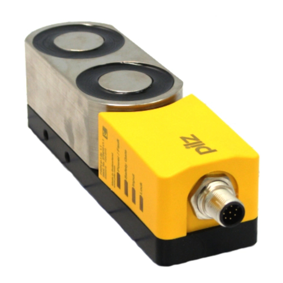
PSEN sl-1.0p 4.1/4.2 Dimensions in mm M5 (6x) 25,9 M12x1 Fig.: Safety switch and locking magnet 22,5 M5 (2x) 2,5° Fig.: Actuator Operating Manual PSEN sl-1.0p 4.1/4.2 1003808-EN-02... -
Page 27: Technical Details Order No. 570671-570672
Classification in accordance with EN 60947-5-3 PDDB PDDB Pilz coding type fully coded uniquely coded Transponder 570671 570672 Frequency band 122 kHz - 128 kHz 122 kHz - 128 kHz Max. transmitter output 15 mW 15 mW Operating Manual PSEN sl-1.0p 4.1/4.2 1003808-EN-02... - Page 28 Inputs typ. 20 ms 20 ms Inputs max. 35 ms 35 ms Actuator typ. 25 ms 25 ms Actuator max. 260 ms 260 ms Risk time in accordance with EN 60947-5-3 260 ms 260 ms Operating Manual PSEN sl-1.0p 4.1/4.2 1003808-EN-02...
- Page 29 Magnetic holding force on 1.000 N 1.000 N Magnetic holding force off 30 N 30 N Max. vertical offset 5 mm 5 mm Max. lateral offset 3 mm 3 mm Max. angular offset 2,5 deg 2,5 deg Operating Manual PSEN sl-1.0p 4.1/4.2 1003808-EN-02...
-
Page 30: Technical Details Order No. 570674-570675
TÜV, cULus Listed Sensor's mode of operation Transponder Transponder Coding level in accordance with EN ISO 14119 High High Design in accordance with EN ISO 14119 Classification in accordance with EN 60947-5-3 PDDB PDDB Operating Manual PSEN sl-1.0p 4.1/4.2 1003808-EN-02... - Page 31 Test pulse duration, safety outputs 450 µs 450 µs Switch-on delay after UB is applied 1,6 s 1,6 s Inputs typ. 20 ms 20 ms Inputs max. 35 ms 35 ms Actuator typ. 500 ms 500 ms Operating Manual PSEN sl-1.0p 4.1/4.2 1003808-EN-02...
- Page 32 Number of shocks Acceleration Duration 16 ms 16 ms Airgap creepage Overvoltage category Pollution degree Rated insulation voltage 75 V 75 V Rated impulse withstand voltage 1 kV 1 kV Protection type Housing IP67 IP67 Operating Manual PSEN sl-1.0p 4.1/4.2 1003808-EN-02...
- Page 33 22 mm 22 mm Weight of safety switch 1.120 g 1.120 g Weight of actuator 590 g 590 g Weight 1.710 g 1.710 g Where standards are undated, the 2015-04 latest editions shall apply. Operating Manual PSEN sl-1.0p 4.1/4.2 1003808-EN-02...
-
Page 34: Supplementary Data
2) this product must accept any interference received, including interference that may cause undesired operation. Changes or modifications made to this product not expressly approved by Pilz may void the FCC authorization to operate this equipment. NOTE: This equipment has been tested and found to comply with the limits for a Class A digital device, pursuant to Part 15 of the FCC Rules. -
Page 35: Order Reference
European Parliament and of the Council. The complete EC Declaration of Conformity is available on the Internet at www.pilz.com/downloads. Representative: Norbert Fröhlich, Pilz GmbH & Co. KG, Felix-Wankel-Str. 2, 73760 Ost- fildern, Germany Operating Manual PSEN sl-1.0p 4.1/4.2... - Page 36 Back cover Support Technical support is available from Pilz round the clock. Americas Australia Scandinavia Brazil +61 3 95600621 +45 74436332 +55 11 97569-2804 Spain Canada Europe +34 938497433 +1 888-315-PILZ (315-7459) Austria Switzerland Mexico +43 1 7986263-0 +41 62 88979-30...