
Related Manuals for Pico Macom MCM-30


Summary of Contents for Pico Macom MCM-30
- Page 1 MCM-30 31dB Adjustable VHF-Band Distribution Amplifier Installation and Operation Manual Operation www.picomacom.com Ph: 800-421-6511 Manual Rev. 06/03...
-
Page 2: Product Inspection
To insure proper installation and operation, take a moment to read this guide before proceeding with the installation. If you have any questions or comments about the MCM-30 31dB Adjustable VHF-Band Distribution Amplifier, please contact your dealer or have him contact the PICO MACOM Service Center at these phone numbers: 800-421-6511, 818-493-4300. - Page 3 21. Outdoor Antenna Grounding: Before attempting to install this product, be sure the antenna or cable system is grounded so as to MCM-30 provide some protection against voltage surges and built-up static charges.
- Page 4 Descriptions MCM-30 31dB Adjustable VHF-Band Distribution Amplifier 31dB Adjustable VHF-Band Distribution Amplifier Cost-Effective VHF Amplifier – 13 Off-Air Channel Range (54-216MHz) suitable for small to large MATV-SMATV systems – Very Low-Noise and Distortion – 15dB Independently adjustable VHF High-Low Band-gain controls for optimal carrier-to-noise ratio and balancing –...
-
Page 5: Specifications
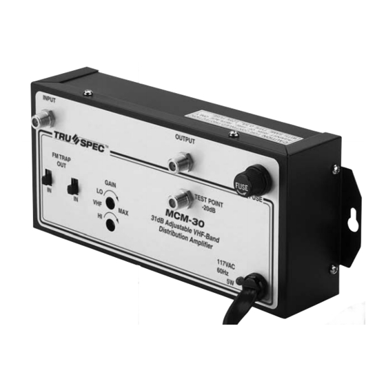
31dB Adjustable VHF-Band Distribution Amplifier INPUT SPEC FM TRAP GAIN Channel Loading Specifications Total # of Channels Ordering Information MCM-30 Specifications MCM-30 OUTPUT TEST POINT -20dB MCM-30 31dB Adjustable VHF-Band Distribution Amplifier 117VAC 60Hz Max. Input Level Max. Output Level... -
Page 6: Operation And Controls
Operation and Controls MCM-30 INPUT FM TRAP Front Panel Input: Connect input cable to this port. FM Trap: Place switch to the “IN” position to attenuate FM frequencies 88 to 96 MHz –20dB. FM Trap: Place switch to the “IN” position to attenuate FM frequencies 95 to 108 MHz –20dB. -
Page 7: Installation Procedure
Connect an F type jumper cable from the OUTPUT connector of the MCM-30 to the distribution system. Plug the power cable into a polarized electrical outlet Connect a RF signal level meter to the MCM-30 test point connection and adjust the output level to match the distribution level requirements Installation Procedure... -
Page 8: Limited Warranty
We will issue an invoice for the List Price of the loaner unit plus shipping costs. When you receive the loaner unit, pack the failed unit in the loaner unit’s box and ship it freight prepaid to Pico Macom for repair. When you receive the repaired unit, a new RMA number will be provided in the box. Carefully pack the loaner unit and affix the new RMA number on the box and ship it back to us for full credit excluding shipping costs.