Table of Contents
Advertisement
Available languages
Available languages
Quick Links
Item # 619-017, 619-030
Model # 54461, 54462
UL Model # EF200B-44
USE AND CARE GUIDE
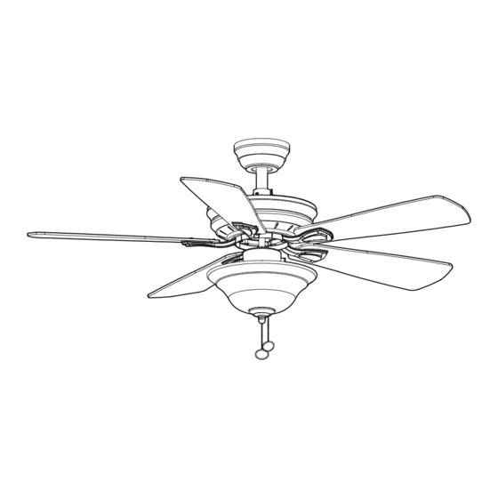
WELLSTON 44-INCH CEILING FAN
Questions, problems, missing parts? Before returning to the store,
call Hampton Bay Customer Service
8 a.m. - 6 p.m., EST, Monday-Friday.
1-877-527-0313
HAMPTONBAY.COM
THANK YOU
We appreciate the trust and confidence you have placed in Hampton Bay through the purchase of this ceiling fan. We strive to continually create
quality products designed to enhance your home. Visit us online to see our full line of products available for your home improvement needs.
Thank you for choosing Hampton Bay!
Advertisement
Chapters
Table of Contents

Related Manuals for HAMPTON BAY WELLSTON EF200B-44


Summary of Contents for HAMPTON BAY WELLSTON EF200B-44
- Page 1 THANK YOU We appreciate the trust and confidence you have placed in Hampton Bay through the purchase of this ceiling fan. We strive to continually create quality products designed to enhance your home. Visit us online to see our full line of products available for your home improvement needs.
-
Page 2: Table Of Contents
Table of Contents Table of Contents ..............2 Assembly ................7 Safety Information ............... 2 Operation ................12 Warranty ................3 Care and Cleaning ............. 13 Pre-Installation ..............3 Troubleshooting ..............13 Installation ................6 Safety Information All wiring must be in accordance with the National Electrical WARNING: To reduce the risk of personal injury, Code ANSI/NFPA 70 and local electrical codes. -
Page 3: Warranty
A certain amount of “wobble” is normal and should not be considered a defect. Servicing performed by unauthorized persons shall render the warranty invalid. There is no other express warranty. Hampton Bay hereby disclaims any and all warranties, including but not limited to those of merchantability and fitness for a particular purpose to the extent permitted by law. - Page 4 Pre-Installation (continued) HARDWARE INCLUDED NOTE: Hardware not shown to actual size. Part Description Quantity Part Description Quantity Blade attachment screws Rubber Gasket Wire connecting nut Hanger pin Pull chain Locking pin...
- Page 5 Pre-Installation (continued) PACKAGE CONTENTS Part Description Quantity Part Description Quantity Slide-on mounting bracket Light kit fitter assembly (inside canopy) Blade Ball/downrod assembly Blade bracket Canopy Glass bowl Fan-motor assembly CFL bulb, 14-watts maximum IMPORTANT: This product and/or components are governed by one or more of the following U.S. Patents: 5,947,436;...
-
Page 6: Installation
Installation MOUNTING OPTIONS WARNING: To reduce the risk of fire, electric shock NOTE: You may need a longer downrod to maintain or personal injury, mount to outlet box marked proper blade clearance when installing on a steep, sloped “Acceptable for fan support of 35lbs. (15.9 Kg) or less”, ceiling. - Page 7 Assembly - Standard Ceiling Mount Preparing for mounting Routing the wires □ □ Remove the mounting plate (A) from the canopy (C) by Route the wires exiting the top of the fan motor (D) loosening the four screws on the top of the canopy (C). through the canopy (C) and then through the ball/ □...
- Page 8 Assembly - Close-To-Ceiling Mount Close-to-Ceiling Mounting Routing the wires □ □ Remove the mounting bracket (A) from the canopy (C) by Remove three of the six screws and lock washers (every other loosening the four screws on the top of the canopy (C). one) securing the motor collar (M) to the top of the fan motor □...
-
Page 9: Assembly
Assembly - Hanging the Fan (continued) Hanging the fan Making the electrical connection WARNING: Each wire not supplied with this fan is designed to WARNING: The hook as shown is only to balance the fan while accept up to one 12-gauge house wire and two wires from the attaching wiring. - Page 10 Assembly - Hanging the Fan (continued) Mounting the fan Close-to-Ceiling mounting WARNING: The locking slots of the ceiling canopy are provided only WARNING: When using the standard ball/downrod mounting, the as an aid to mounting. Do not leave the fan assembly unattended tab in the ring at the bottom of the mounting bracket must rest in until all four canopy screws are engaged and firmly tightened.
- Page 11 Assembly - Attaching the Light Kit Attaching the light kit CAUTION: To reduce the risk of electric shock, disconnect the electrical supply circuit to the fan before installing the light kit. □ Remove the three screws (QQ) from the light kit fitter assembly (E) below the fan motor assembly (D).
-
Page 12: Operation
Operation Turn on the power and check the operation of the fan. The pull chain controls the fan speeds as follows: 1 pull - High, 2 pulls - Medium, 3 pulls - Low, 4 pulls - off The appropriate speed settings for warm or cool weather depends on factors such as the room size, ceiling height, and number of fans. -
Page 13: Care And Cleaning
Care and Cleaning WARNING: Make sure the power is off before cleaning your fan. □ Because of the fan’s natural movement, some connections may become loose. Check the support connections, brackets, and blade attachments twice a year. Make sure they are secure. It is not necessary to remove the fan from the ceiling. □... - Page 14 Questions, problems, missing parts? Before returning to the store, call Hampton Bay Customer Service 8 a.m. - 6 p.m., EST, Monday-Friday 1-877-527-0313 HAMPTONBAY.COM Retain this manual for future use.
- Page 15 GRACIAS POR TU COMPRA Apreciamos la confianza que has depositado en Hampton Bay al comprar este ventilador de techo. Nos esforzamos para continuamente crear productos de calidad diseñados para tu hogar. Visítanos por Internet para ver nuestra línea completa de productos disponibles para las necesidades de mejoras de tu hogar.
-
Page 16: Información De Seguridad
Tabla de Contenido Tabla de Contenido ............. 2 Información de Seguridad ..........2 Garantía ................3 Preinstalación ..............3 Instalación ................6 Ensamblaje ................7 Funcionamiento ..............12 Mantenimiento y Limpieza..........13 Solución de Problemas ............. 13 Información de Seguridad Todo el cableado debe cumplir con el Código Nacional de ADVERTENCIA: Para reducir el riesgo de lesiones, no Electricidad ANSI/NFPA 70 y con los códigos locales de... -
Page 17: Garantía
Cualquier servicio técnico conducido por personas no autorizadas anulará la garantía. No hay ninguna otra garantía expresa. Mediante la presente Hampton Bay se exime de cualquier garantía, incluyendo pero sin limitarse a aquellas de comercial- ización e idoneidad para un fin particular, de acuerdo a lo contemplado por la ley. - Page 18 Preinstalación (continuación) HERRAJES INCLUIDOS NOTA: No se muestra el tamaño real de los herrajes. Pieza Descripción Cantidad Pieza Descripción Cantidad Tornillos para el montaje de aspas Junta de goma Tuerca para conectar cables Interruptor de cadena Pasador de soporte Pasador de cierre...
- Page 19 Preinstalación (continuación) CONTENIDO DEL PAQUETE Pieza Descripción Cantidad Pieza Descripción Cantidad Soporte de montaje deslizante Ensamblaje del soporte del kit de luces (dentro de la cubierta) Aspa Ensamblaje de tubo bajante/bola Soporte de aspa Cubierta Tazón de vidrio Ensamblaje del motor del ventilador Bombilla CFL, máximo de 14 Watts IMPORTANTE: Este producto y/o sus componentes están protegidos por una o más de las siguientes Patentes de...
-
Page 20: Instalación
Instalación OPCIONES DE MONTAJE ADVERTENCIA: Para reducir el riesgo de incendio, descarga NOTA:Tal vez necesites un tubo bajante más largo para eléctrica o lesiones personales, monta el ventilador sobre una caja mantener la altura mínima adecuada de las aspas al eléctrica marcada como “aprobada como soporte de ventiladores de instalar el ventilador en un techo inclinado. - Page 21 Ensamblaje – Montaje Estándar en Techo Preparación para el montaje Disposición de los cables □ □ Retira la placa de montaje (A) de la cubierta (C) Inserta los cables que salen por la parte superior del aflojando los cuatro tornillos en la parte superior de la motor del ventilador (D) a través de la cubierta (C) y luego cubierta (C).
- Page 22 Ensamblaje – Montaje "Cerca del Techo" Montaje "Cerca del Techo" Disposición de los cables □ □ Retira el soporte de montaje (A) de la cubierta (C) aflojando Retira tres de los seis tornillos y arandelas de seguridad los cuatro tornillos en la parte superior de la cubierta (C). (alternados) que sujetan el collarín del motor (M) a la parte □...
-
Page 23: Ensamblaje
Ensamblaje – Cómo Colgar el Ventilador (continuación) Cómo colgar el ventilador Cómo hacer las conexiones eléctricas ADVERTENCIA: Cada cable no suministrado con este ventilador ADVERTENCIA: El gancho usado como se muestra es sólo para está diseñado para aceptar un máximo de un solo circuito eléctrico sostener el ventilador mientras se conectan los cables. - Page 24 Ensamblaje – Cómo Colgar el Ventilador (continuación) Cómo montar el ventilador Montaje "Cerca del Techo" ADVERTENCIA: Las ranuras de cierre de la cubierta del techo se ADVERTENCIA: Cuando uses el montaje del tubo bajante/bola estándar, incluyen solamente como una ayuda para el montaje. No dejes sin la pestaña en el aro en la parte inferior del soporte de montaje debe supervisión el ensamblaje del ventilador hasta que los cuatro tornillos encajar en la ranura de la bola de soporte.
- Page 25 Ensamblaje – Cómo Instalar el Kit de Luces Cómo instalar el kit de luces PRECAUCIÓN: Para disminuir el riesgo de descarga eléctrica, desconecta el circuito de energía del ventilador antes de instalar el kit de luces. □ Quita los tres tornillos (QQ) de la ensamblaje del soporte del kit de luces, debajo del ensamblaje del motor del ventilador (D).
-
Page 26: Funcionamiento
Funcionamiento Enciende la electricidad y verifica el funcionamiento del ventilador. El interruptor de cadena controla las velocidades del ventilador de la siguiente manera: Halar 1 vez: Alto, halar 2 veces: Medio, halar 3 veces: Bajo y halar 4 veces: Apagado Las configuraciones de velocidad apropiadas para clima cálido o frío dependen de factores como el tamaño de la habitación, la altura del techo y la cantidad de ventiladores. -
Page 27: Mantenimiento Y Limpieza
Mantenimiento y Limpieza ADVERTENCIA: Asegúrate de que la corriente esté apagada antes de limpiar el ventilador. □ Debido al movimiento natural del ventilador, algunas conexiones pueden aflojarse. Revisa las conexiones de soporte, soportes y accesorios de aspas dos veces al año. Verifica que estén seguros. No es necesario desmontar el ventilador del techo. □... - Page 28 ¿Preguntas, problemas o piezas faltantes? Antes de regresar a la tienda, llama al Servicio al Cliente de Hampton Bay de Lunes a Viernes entre 8 a.m. y 6 p.m., (hora del Este de EE. UU.) 1-877-527-0313 HAMPTONBAY.COM Conserva este manual para uso en el futuro.