Table of Contents
Advertisement
Quick Links
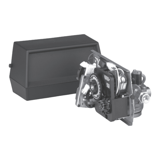
Fleck 2750 Downflow
Service Manual
TABLE OF CONTENTS
JOB SPECIFICATION SHEET ...............................................1
INSTALLATION ......................................................................2
START-UP INSTRUCTIONS ..................................................2
3200 TIMER SETTING PROCEDURE ...................................3
3210 TIMER SETTING PROCEDURE ...................................4
3200, 3210, 3220, 3230 REGENERATION CYCLE SETTING
PROCEDURE .........................................................................5
3200 TIME CLOCK TIMER ASSEMBLY .................................6
3210 METER DELAYED TIMER ASSEMBLY ........................7
3220 METER IMMEDIATE TIMER ASSEMBLY .....................8
3230 REMOTE START TIMER ASSEMBLY ...........................9
POWERHEAD ASSEMBLY (ENVIRONMENTAL) ..................10
MANUAL POWERHEAD ASSEMBLY ....................................11
CONTROL VALVE WITH 1700 INJECTOR ............................12
1600 BRINE SYSTEM ASSEMBLY ........................................13
1600 BRINE SYSTEM ASSEMBLY ........................................14
1700 SERIES BRINE SYSTEM ASSEMBLY ..........................15
1710 BRINE SYSTEM ASSEMBLY ........................................16
1" METER ASSEMBLY ...........................................................17
(OLD STYLE) .........................................................................18
(NEW STYLE) ........................................................................19
2300 SAFETY BRINE VALVE.................................................20
2310 SAFETY BRINE VALVE.................................................21
TROUBLESHOOTING ...........................................................22
GENERAL SERVICE HINTS FOR METER CONTROL .........23
WATER CONDITIONER FLOW DIAGRAMS .........................24
FLOW DATA & INJECTOR DRAW RATES ............................25
SYSTEM #4 ............................................................................26
SYSTEM #5 INTERLOCK ......................................................26
SYSTEM #6 ............................................................................26
SYSTEM #7 ............................................................................26
SYSTEM #4 IMMEDIATE & DELAYED VALVE WIRING ........28
SYSTEM #5 DUPLEX VALVE WIRING ..................................30
SYSTEM #6 DUPLEX VALVE WIRING ..................................31
SYSTEM #7 DUPLEX 230V 3-WAY VALVE WIRING.............33
SERVICE ASSEMBLIES ........................................................34
JOB SPECIFICATION SHEET
Job Number: ___________________________________________________
Model Number: _________________________________________________
Water Hardness: _______________________________________ ppm or gpg
Capacity Per Unit: _______________________________________________
Mineral Tank Size: ______________ Diameter: ________ Height: _________
Salt Setting per Regeneration: _____________________________________
1. Type of Timer:
A. 7 Day or 12 Day
B. Meter Initiated
2. Downflow:
Upflow
3. Meter Size:
A. 3/4" Std Range (125 - 2,100 gallon setting)
B. 3/4" Ext Range (625 - 10,625 gallon setting)
C. 1" Std Range (310 - 5,270 gallon setting)
D. 1" Ext Range (1,150 - 26,350 gallon setting)
E. 1-1/2" Std Range (625 - 10,625 gallon setting)
F. 1-1/2" Ext Range (3,125 - 53,125 gallon setting)
G. 2" Std Range (1,250 - 21,250 gallon setting)
H. 2" Ext Range (6,250 - 106,250 gallon setting)
I.
3" Std Range (3,750 - 63,750 gallon setting)
J. 3" Ext Range (18,750 - 318,750 gallon setting)
K. Electronic _________ Pulse Count ________ Meter Size _______
4. System Type:
A. System #4: 1 Tank, 1 Meter, Immediate, or Delayed Regeneration
B. System #4: Time Clock
C. System #4: Twin Tank
D. System #5: 2-5 Tanks, Interlock Mechanical
2-4 Tanks, Interlock Electronic
Meter per unit for Mechanical and Electronic
E. System #6: 2-5 Tanks, 1 Meter, Series Regeneration, Mechanical
2-4 Tanks, 1 Meter, Series Regeneration, Electronic
F. System #7: 2-5 Tanks, 1 Meter, Alternating Regeneration,
Mechanical
2 Tanks only, 1 Meter, Alternating Regeneration,
Electronic
G. System #9: Electronic Only, 2-4 Tanks, Meter per Valve, Alternating
H. System #14: Electronic Only, 2-4 Tanks, Meter per Valve.
Brings units on and offline based on flow.
5. Timer Program Settings:
A. Backwash: ___________________________________ Minutes
B. Brine and Slow Rinse: __________________________ Minutes
C. Rapid Rinse: _________________________________ Minutes
D. Brine Tank Refill: ______________________________ Minutes
E. Pause Time: __________________________________ Minutes
F. Second Backwash: ____________________________ Minutes
6. Drain Line Flow Control: ______________________________gpm
7. Brine Line Flow Controller: ____________________________gpm
8. Injector Size#: ____________________________________________
9. Piston Type:
A. Hard Water Bypass
B. No Hard Water Bypass
Upflow Variable
BR42327 Rev C
MY10
Advertisement
Table of Contents

Related Manuals for Pentair Pool Products Fleck 2750

Summary of Contents for Pentair Pool Products Fleck 2750
-
Page 1: Table Of Contents
Fleck 2750 Downflow Service Manual TABLE OF CONTENTS JOB SPECIFICATION SHEET JOB SPECIFICATION SHEET ..........1 Job Number: ___________________________________________________ Model Number: _________________________________________________ INSTALLATION ..............2 Water Hardness: _______________________________________ ppm or gpg START-UP INSTRUCTIONS ..........2 Capacity Per Unit: _______________________________________________ 3200 TIMER SETTING PROCEDURE ........3 Mineral Tank Size: ______________ Diameter: ________ Height: _________ 3210 TIMER SETTING PROCEDURE ........4... -
Page 2: Installation
INSTALLATION 11. Slowly place the by-pass in service position and let water Water Pressure flow into the mineral tank. When water flow stops, slowly A minimum of 20 pounds (1.4 bar) of water pressure is required open a cold water tap nearby and let run until the air is for regeneration valve to operate effectively. -
Page 3: 3200 Timer Setting Procedure
3200 TIMER SETTING PROCEDURE How To Set Days On Which Water Conditioner Is To Regenerate (Figure 2) Rotate the skipper wheel until the number “1” is at the red pointer. Set the days that regeneration is to occur by sliding tabs on the skipper wheel outward to expose trip fingers. -
Page 4: 3210 Timer Setting Procedure
3210 TIMER SETTING PROCEDURE Typical Programming Procedure Calculate the gallon capacity of the system, subtract the necessary reserve requirement and set the gallons available opposite the small white dot on the program wheel gear (Figure NOTE: Drawing shows 8,750 gallon setting. The capacity (gallons) arrow (15) shows zero gallons remaining. -
Page 5: Procedure
3200, 3210, 3220, 3230 REGENERATION CYCLE SETTING PROCEDURE How To Set The Regeneration Cycle Program How To Change The Length Of Brine Tank Refill Time The regeneration cycle program on your water conditioner has 1. The second group of holes in the program wheel been factory preset, however, portions of the cycle or program determines the length of time that your water conditioner may be lengthened or shortened in time to suit local conditions. -
Page 6: 3200 Time Clock Timer Assembly
3200 TIME CLOCK TIMER ASSEMBLY 61502-3200 Rev A Item No. Part No. Description Item No. Part No. Description 1 ....1 ..13870 ....Housing, Timer, 3200 17 ....1 ..15424 ....Spring, Detent, Timer 2 ....1 ..14265 ....Clip, Sping 18 ....1 ..15066 ....Ball, 1/4”, Delrin 3 ....3 .. -
Page 7: 3210 Meter Delayed Timer Assembly
3210 METER DELAYED TIMER ASSEMBLY 61502-3210 Rev A Item No. Part No. Description Item No. Part No. Description 1 ....1 ..13870 ....Housing, Timer, 3200 1 ..19660-1 .....Motor, 230V, 60Hz, 1/30 RPM 2 ....1 ..13802 ....Gear, Cycle Actuator 19 ....1 .. -
Page 8: 3220 Meter Immediate Timer Assembly
3220 METER IMMEDIATE TIMER ASSEMBLY 61502-3220 Rev B Item No. Part No. Description Item No. Part No. Description 1 ....1 ..13870 ....Housing, Timer 18 ....1 ..14501 ....Clutch, Drive Pinion 2 ....1 ..15431 ....Gear, Cycle Actuator, System #5 19 ....1 .. -
Page 9: 3230 Remote Start Timer Assembly
3230 REMOTE START TIMER ASSEMBLY 61502-3230R REV A Item No. Part No. Description Item No. Part No. Description 1 ....1 ..13870 ....Housing, Timer 1 ..18824-1 .....Motor, 23V, 50Hz, 1/30 RPM 2 ....1 ..14265 ....Spring Clip 1 ..18826-1 .....Motor, 24V, 50Hz, 1/30 RPM 3 ....3 .. -
Page 10: Powerhead Assembly (Environmental)
POWERHEAD ASSEMBLY (ENVIRONMENTAL) BR61501-2750 Rev E Item No. Part No. Description Item No. Part No. Description 1 ....1 ..18697-13 ...Backplate, Hinged, 2900 12 ....2 ..14923 ....Screw, Pan Hd Mach, 4-40 x 1 2 ....1 ........Timer: 3200 7 Day, 3200 12 Day, 13 ....2 .. -
Page 11: Manual Powerhead Assembly
MANUAL POWERHEAD ASSEMBLY 60409 Rev G Item No. Part No. Description 1 ....1 ..12593 ....Backplate, Manual 2 ....1 ..12592 ....Bracket, Lever Position 3 ....1 ..12596 ....Screw, Spec Mach, 1/4 - 20 x 1/2 4 ....1 ..12707 ....Washer, Spring 6 ....1 .. -
Page 12: Control Valve With 1700 Injector
CONTROL VALVE WITH 1700 INJECTOR Item No. Part No. Description Item No. Part No. Description 1 ....1 ..14749 ....Valve Body, 2750 18 ....1 ..60365-00 ...Housing, DLFC, 1/2”F x 3/4”F 2 ....6 ..10545 ....Seal, Piston 19 ....2 ..11710 ....O-ring, -215 20 ....1 .. -
Page 13: 1600 Brine System Assembly
1600 BRINE SYSTEM ASSEMBLY 60029 Rev C Item No. Part No. Description Item No. Part No. Description 1 ....1 ..10328 ....Elbow, 90 Deg. 1/4 NPT x 3/8 17 ....1 ..12552-02 ...Brine Valve Stem, 1600, w/Seat Tube 18 ....1 ..12626 ....Seat, Brine Valve 2 ....1 .. - Page 14 1600 BRINE SYSTEM ASSEMBLY 60011 Rev C Item No. Part No. Description Item No. Part No. Description 1 ....1 ..10329 ....Fitting, Tube, 3/8 Nut, Brass 16 ....2 ..10692 ....Screw, Slot Hex Hd, 10 - 24X 18-8 Stainless Steel 2 ....1 ..
-
Page 15: 1700 Series Brine System Assembly
1700 SERIES BRINE SYSTEM ASSEMBLY Item No. Part No. Description Item No. Part No. Description 1 ....1 ..14792 ....Plug, End, Brine Valve 17 ....1 ..15416 ....Tube, Brine, 2900/2750 2 ....1 ..13201 ....Quad Ring, -020 1 ..16460 ....Tube, Brine, 2850/2900s 3 ....1 .. -
Page 16: 1710 Brine System Assembly
1710 BRINE SYSTEM ASSEMBLY 60604 Rev F Item No. Part No. Description Item No. Part No. Description 1 ....1 ..41202 ....Brine Valve, 1700, Plastic, Top 20 ....1 ..16460 ....Tube, Brine, 2850, 2900s 2 ....1 ..14785-01 ...Retainer, Flow Control 1 .. -
Page 17: 1" Meter Assembly
1" METER ASSEMBLY 60391 Rev d Item No. Part No. Description 1 ....1 ..14959 ....Body, Meter, 2750 2 ....1 ..13882 ....Post, Meter Impeller 3 ....1 ..13509 ....Impeller, Meter 4 ....1 ..13847 ....O-ring, -137, Std/560CD, Meter 5A .....1 ..15218 ....Meter Cap Assembly, Brass, Hot Water 5B .....1 .. -
Page 18: 1600 Service Valve Operator (Old Style)
1600 SERVICE VALVE OPERATOR (OLD STYLE) 60150 Rev A Item No. Part No. Description 1 ....1 ..11749 ....Guide, Brine Valve Stem 2 ....1 ..10250 ....Ring, Retaining 3 ....1 ..10249 ....Spring, Brine Valve 4 ....1 ..12550 ....Quad Ring, -009 5 ....1 .. -
Page 19: 1600 Service Valve Operator (New Style)
1600 SERVICE VALVE OPERATOR (NEW STYLE) 60150 Rev A Item No. Part No. Description 1 ....1 ..11749 ....Guide, Brine Valve Stem 2 ....1 ..10250 ....Ring, Retaining 3 ....1 ..10249 ....Spring, Brine Valve 4 ....1 ..12550 ....Quad Ring, -009 5 ....2 .. -
Page 20: 2300 Safety Brine Valve
2300 SAFETY BRINE VALVE 60027 Rev D Item No. Part No. Description 1 ....1 ..60027-00 ...Safety Brine Valve, 2300, Less Elbow 2 ....1 ..10138 ....Ball, 3/8", Brass 3 ....1 ..11566 ....Ball Stop, Slow Fill 4 ....1 ..10328 ....Fitting, Elbow, 90 Deg. 1/4 NPT x 3/8 Tube 5 ....1 .. -
Page 21: 2310 Safety Brine Valve
2310 SAFETY BRINE VALVE Item No. Part No. Description 1 ....1 ..19645 ....Body, Safety Brine Valve, 2310 2 ....1 ..19803 ....Safety Brine Valve Assy 3 ....1 ..19804 ....Screw, Sckt Hd, Set, 10-24 x .75 4 ....1 ..19805 ....Nut, Hex, 10-24, Nylon Black 5 ....1 .. - Page 22 2350 SAFETY BRINE VALVE ASSEMBLY 42303 REV A Item No. Part No. Description 1 ....1 ..60038 ....Safety Brine Valve, 2350 1A .....1 ..61024 ....Actuator Assembly, 2350 Brine 2 ....1 ..60028-30 ...Float Assembly, 2350, 30” Wht ....1 ..60026-30SAN ...Float Assembly, 2350, 30”, HW 3 ....1 ..
-
Page 23: Troubleshooting
TROUBLESHOOTING Problem Cause Correction Water conditioner fails to Electrical service to unit has been Assure permanent electrical service (check fuse, regenerate. interrupted plug, pull chain, or switch) Timer is defective. Replace timer. Power failure. Reset time of day. Hard water. By-pass valve is open. -
Page 24: General Service Hints For Meter Control
GENERAL SERVICE HINTS FOR METER CONTROL Problem: Softener delivers hard water Reason: Reserve capacity has been exceeded. Correction: Check salt dosage requirements and reset program wheel to provide additional reserve. Reason: Program wheel is not rotating with meter output. Correction: Pull cable out of meter cover and rotate manually. Program wheel must move without binding and clutch must give positive clicks when program wheel strikes regeneration stop. -
Page 25: Water Conditioner Flow Diagrams
WATER CONDITIONER FLOW DIAGRAMS 4 Slow Rinse Position 1 Service Position 2 Backwash Position 5 Rapid Rinse Position 6 Brine Tank Fill Position 3 Brine Position Fleck 2750 Downflow MY10 • 25... -
Page 26: Flow Data & Injector Draw Rates
FLOW DATA & INJECTOR DRAW RATES 26 • MY10 Fleck 2750 Downflow... -
Page 27: System #4
SYSTEM #4 SYSTEM #6 Typical Tank Installation with Optional Meter Twin Series Regeneration Installation with a Remote Meter SYSTEM #7 Twin Alternator Installation with a Remote Meter SYSTEM #5 INTERLOCK Typical Twin Tank Installation with Optional 2 Meter Interlock and No Hard Water Bypass Fleck 2750 Downflow MY10 • 27... -
Page 28: System #4 Immediate & Delayed Valve Wiring
SYSTEM #4 IMMEDIATE & DELAYED VALVE WIRING 28 • MY10 Fleck 2750 Downflow... -
Page 29: System #4 Remote Signal Start Valve Wiring
SYSTEM #4 REMOTE SIGNAL START VALVE WIRING Fleck 2750 Downflow MY10 • 29... -
Page 30: System #5 Duplex Valve Wiring
SYSTEM #5 DUPLEX VALVE WIRING 40502-01 REV C 40502-02 REV C 30 • MY10 Fleck 2750 Downflow... -
Page 31: System #6 Duplex Valve Wiring
SYSTEM #6 DUPLEX VALVE WIRING 13632-01 REV L 13632-02 REV L Fleck 2750 Downflow MY10 • 31... -
Page 32: System #7 Duplex 24V/120V 3-Way Valve Wiring
SYSTEM #7 DUPLEX 24V/120V 3-WAY VALVE WIRING 19138-01 REV E 19138-02 REV E 32 • MY10 Fleck 2750 Downflow... -
Page 33: System #7 Duplex 230V 3-Way Valve Wiring
SYSTEM #7 DUPLEX 230V 3-WAY VALVE WIRING 17727-01 REV E 17727-02 REV E Fleck 2750 Downflow MY10 • 33... -
Page 34: Drain Line Flow Control
SERVICE ASSEMBLIES 24 Hour Gear Assembly: Piston Assemblies: 19205......Gear Assy, 24 Hour, Silver, 5600, 12AM 60090-HF....Piston Assy, 2750/2900 60091-HF....Piston Assy, 2750, Hot Water 60519-02 ....Gear Assy, 24 Hour, 2 Times a Day Regen 60101-00 ....Piston Assy, 2750 NHWBP Filter, 60519-03 ....Gear Assy, 24 Hour, 3 Times a Day Conversion Kit Regen 60101-01 ....Piston Assy, 2750 NHWBP... - Page 35 Fleck 2750 Downflow MY10 • 35...
- Page 36 © 2010 Pentair Residential Filtration, LLC BR42327 Rev C MY10...