Table of Contents
Advertisement
Quick Links
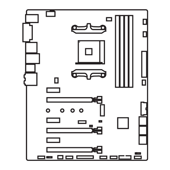
Unpacking
Thank you for buying the MSI
motherboard. Check to make sure your
®
X370 SLI PLUS
motherboard box contains the following items. If something is missing, contact your
dealer as soon as possible.
Drivers & Utilities
Motherboard User
Disc
Guide
Motherboard
I/O Shield
SATA Cable x2
SATA Cable Labels
1
Unpacking
Advertisement
Table of Contents

Related Manuals for MSI X370 SLI PLUS


Summary of Contents for MSI X370 SLI PLUS
-
Page 1: Unpacking
Unpacking Thank you for buying the MSI motherboard. Check to make sure your ® X370 SLI PLUS motherboard box contains the following items. If something is missing, contact your dealer as soon as possible. Drivers & Utilities Motherboard User Disc... -
Page 2: Safety Information
Safety Information The components included in this package are prone to damage from electrostatic discharge (ESD). Please adhere to the following instructions to ensure successful computer assembly. Ensure that all components are securely connected. Loose connections may cause the computer to not recognize a component or fail to start. Hold the motherboard by the edges to avoid touching sensitive components. -
Page 3: Quick Start
Quick Start Preparing Tools and Components AM4 CPU ® Thermal Paste CPU Fan DDR4 Memory Power Supply Unit Chassis SATA Hard Disk Drive Graphics Card SATA DVD Drive A Package of Screws Phillips Screwdriver Quick Start... -
Page 4: Installing A Processor
Installing a Processor https://youtu.be/Xv89nhFk1vc Quick Start... -
Page 5: Installing Ddr4 Memory
Installing DDR4 memory http://youtu.be/T03aDrJPyQs DIMMB2 DIMMB2 DIMMB1 DIMMA2 DIMMA2 DIMMA2 DIMMA1 Quick Start... -
Page 6: Connecting The Front Panel Header
Connecting the Front Panel Header http://youtu.be/DPELIdVNZUI HDD LED + Power LED + HDD LED - Power LED - Reset Switch Power Switch Reset Switch Power Switch JFP1 Reserved No Pin JFP1 HDD LED - HDD LED HDD LED + POWER LED - POWER LED POWER LED + Quick Start... -
Page 7: Installing The Motherboard
Installing the Motherboard Quick Start... -
Page 8: Installing Sata Drives
Installing SATA Drives http://youtu.be/RZsMpqxythc Quick Start... -
Page 9: Installing A Graphics Card
Installing a Graphics Card http://youtu.be/mG0GZpr9w_A Quick Start... -
Page 10: Connecting Peripheral Devices
Connecting Peripheral Devices Quick Start... -
Page 11: Connecting The Power Connectors
Connecting the Power Connectors http://youtu.be/gkDYyR_83I4 ATX_PWR1 CPU_PWR1 Quick Start... -
Page 12: Power On
Power On Quick Start... -
Page 13: Table Of Contents
Contents Unpacking ......................1 Safety Information ....................2 Quick Start ......................3 Preparing Tools and Components ................3 Installing a Processor ..................... 4 Installing DDR4 memory ..................5 Connecting the Front Panel Header ............... 6 Installing the Motherboard ..................7 Installing SATA Drives..................... - Page 14 ® ® Installing Drivers ....................60 Installing Utilities ....................60 LIVE UPDATE 6 ...................... 61 COMMAND CENTER ..................... 63 RAMDISK....................... 67 X-BOOST ....................... 68 MSI SMART TOOL ....................70 NETWORK GENIE ....................72 CPU-Z........................74 Regulatory Notices ....................75 Contents...
-
Page 15: Specifications
Supports ECC UDIMM memory (non-ECC mode) * 7th Gen A-series/ Athlon ™ processors support a maximum of 2400 MHz. Please refer www.msi.com for more information on compatible memory 2x PCIe 3.0 x16 slots (PCIE_2, PCIE_4) RYZEN series processors support x16/x0, x8/x8 mode ƒ... - Page 16 Continued from previous page ASMedia ASM2142 Chipset ® 1x USB 3.1 Gen2 (SuperSpeed USB 10Gbps) Type-C port ƒ on the back panel 1x USB 3.1 Gen2 (SuperSpeed USB 10Gbps) Type-A port ƒ on the back panel X370 Chipset ® 4x USB 3.1 Gen1 (SuperSpeed USB) ports available ƒ...
- Page 17 Continued from previous page 1x 24-pin ATX 12V power connector 1x 8-pin ATX 12V power connector 6x SATA 6Gb/s connectors 2x USB 2.0 connectors (support additional 4 USB 2.0 ports) 2x USB 3.1 Gen1 connectors (support additional 4 USB 3.1 Gen1 ports) 1x 4-pin CPU fan connector 1x 4-pin PUMP fan connector (supports up to 2A)
- Page 18 Continued from previous page Drivers COMMAND CENTER LIVE UPDATE 6 SUPER CHARGER MYSTIC LIGHT RAMDISK Software X-BOOST MSI SMART TOOL NETWORK GENIE Norton Internet Security Solution ™ Google Chrome , Google Toolbar, Google Drive ™ CPU-Z MSI GAMING Audio Boost Turbo M.2...
-
Page 19: Block Diagram
Block Diagram HDMI DVI-D 2 Channel DDR4 Memory 1 x M.2 PCI Express Bus PCIex4 4 x USB 3.1 Gen1 Realtek ALC892 Audio Jacks NV6795 Super I/O P/S2 Mouse / Keyboard PCIe x1 slot PCIe x1 slot PCIe x1 slot PCIe x16 slot 6 x SATA 6Gb/s (support x4 mode) -
Page 20: Rear I/O Panel
Rear I/O Panel Audio Ports USB 3.1 Gen2 PS/2 USB 3.1 Gen1 DVI-D USB 3.1 Gen1 USB 2.0 USB 3.1 Gen2 Type-C LAN Port LED Status Table Link/ Activity LED Speed LED Status Description Status Description No link 10 Mbps connection Yellow Linked Green... -
Page 21: Realtek Hd Audio Manager
Realtek HD Audio Manager After installing the Realtek HD Audio driver, the Realtek HD Audio Manager icon will appear in the system tray. Double click on the icon to launch. Device Selection Advanced Settings Jack Status Application Enhancement Main Volume Connector Strings Profiles... - Page 22 Audio jacks to headphone and microphone diagram Audio jacks to stereo speakers diagram AUDIO INPUT Audio jacks to 7.1-channel speakers diagram AUDIO INPUT Rear Front Side Center/ Subwoofer Rear I/O Panel...
-
Page 23: Overview Of Components
Overview of Components DIMMA1 DIMMB1 SYS_FAN1 DIMMA2 DIMMB2 CPU_FAN1 CPU_PWR1 CPU Socket PUMP_FAN1 SYS_FAN3 ATX_PWR1 SYS_FAN4 PCI_E1 PCI_E2 JUSB4 M2_1 JBAT1 PCI_E3 SATA▼5▲6 JTPM1 PCI_E4 SATA▼1▲2 SATA▼3▲4 PCI_E5 JCI1 PCI_E6 JFP2 JAUD1 JFP1 JLED1 JUSB3 JCOM1 JUSB2 SYS_FAN2 JLPT1 JUSB1 Overview of Components... - Page 24 Component Contents Port Name Port Type Page CPU_FAN1, PUMP_FAN1, Fan Connectors SYS_FAN1~4 CPU_PWR1, ATX_PWR1 Power Connectors CPU Socket AM4 CPU Socket DIMMA1, DIMMA2, DIMM Slots DIMMB1, DIMMB2 JAUD1 Front Audio Connector JBAT1 Clear CMOS (Reset BIOS) Jumper JCI1 Chassis Intrusion Connector JCOM1 Serial Port Connector JFP1, JFP2...
-
Page 25: Cpu Socket
This motherboard is designed to support overclocking. Before attempting to overclock, please make sure that all other system components can tolerate overclocking. Any attempt to operate beyond product specifications is not recommended. MSI does not guarantee the damages or risks caused by ®... -
Page 26: Dimm Slots
Due to AM4 CPU/memory controller official specification limitation, the frequency of memory modules may operate lower than the marked value under the default state. Please refer www.msi.com for more information on compatible memory. Overview of Components... -
Page 27: Pci_E1~6: Pcie Expansion Slots
Important If you install a large and heavy graphics card, you need to use a tool such as MSI Gaming Series Graphics Card Bolster to support its weight to prevent deformation of the slot. For a single PCIe x16 expansion... - Page 28 PCIe bandwidth table For RYZEN series processors Slot Single 2-Way 3-Way ─ ─ ─ PCI_E1 Gen 2.0 x 1 Gen 2.0 x 1 PCI_E2 Gen 3.0 x 16* Gen 3.0 x 16* Gen 3.0 x 8* Gen 3.0 x 8* Gen 3.0 x 8* ─...
- Page 29 Installing SLI graphics cards For power supply recommendations for SLI configurations, please refer to the user guide of your graphics card to make sure you meet all the system requirements. To install SLI graphics cards: Turn off your computer and disconnect the power cord, install two graphics cards into the PCI_E2 and PCI_E4 slots.
-
Page 30: M2_1: M.2 Slot (Key M)
M2_1: M.2 Slot (Key M) Video Demonstration Watch the video to learn how to use M.2 Shield. https://youtu.be/b-N28ajX_C4 Installing M.2 module Remove the screw from the base screw. Remove the base screw. Tighten the base screw into the hole of the distance to the M.2 slot as the length your M.2 module. -
Page 31: Sata1~6: Sata 6Gb/S Connectors
SATA1~6: SATA 6Gb/s Connectors These connectors are SATA 6Gb/s interface ports. Each connector can connect to one SATA device. SATA6 SATA5 SATA2 SATA1 SATA4 SATA3 Important Please do not fold the SATA cable at a 90-degree angle. Data loss may result during transmission otherwise. -
Page 32: Cpu_Pwr1, Atx_Pwr1: Power Connectors
CPU_PWR1, ATX_PWR1: Power Connectors These connectors allow you to connect an ATX power supply. CPU_PWR1 Ground +12V Ground +12V Ground +12V Ground +12V +3.3V +3.3V +3.3V -12V Ground Ground PS-ON# Ground Ground Ground ATX_PWR1 Ground Ground PWR OK 5VSB +12V +12V +3.3V Ground... -
Page 33: Jusb1~2: Usb 2.0 Connectors
JUSB1~2: USB 2.0 Connectors These connectors allow you to connect USB 2.0 ports on the front panel. USB0- USB1- USB0+ USB1+ Ground Ground No Pin Important Note that the VCC and Ground pins must be connected correctly to avoid possible damage. -
Page 34: Cpu_Fan1, Pump_Fan1, Sys_Fan1~4: Fan Connectors
CPU_FAN1, PUMP_FAN1, SYS_FAN1~4: Fan Connectors Fan connectors can be classified as PWM (Pulse Width Modulation) Mode or DC Mode. PWM Mode fan connectors provide constant 12V output and adjust fan speed with speed control signal. DC Mode fan connectors control fan speed by changing voltage. When you plug a 3-pin (Non-PWM) fan to a fan connector in PWM mode, the fan speed will always maintain at 100%, which might create a lot of noise. -
Page 35: Jaud1: Front Audio Connector
JAUD1: Front Audio Connector This connector allows you to connect audio jacks on the front panel. MIC L Ground MIC R Head Phone R MIC Detection SENSE_SEND No Pin Head Phone L Head Phone Detection JCI1: Chassis Intrusion Connector This connector allows you to connect the chassis intrusion switch cable. Normal Trigger the chassis intrusion event... -
Page 36: Jfp1, Jfp2: Front Panel Connectors
JFP1, JFP2: Front Panel Connectors These connectors connect to the switches and LEDs on the front panel. JFP1 HDD LED + Power LED + HDD LED - Power LED - Reset Switch Power Switch Reset Switch Power Switch Reserved No Pin Speaker - Buzzer + JFP2... -
Page 37: Jbat1: Clear Cmos (Reset Bios) Jumper
JBAT1: Clear CMOS (Reset BIOS) Jumper There is CMOS memory onboard that is external powered from a battery located on the motherboard to save system configuration data. If you want to clear the system configuration, set the jumpers to clear the CMOS memory. Keep Data Clear CMOS/ Reset BIOS... -
Page 38: Jcom1: Serial Port Connector
JCOM1: Serial Port Connector This connector allows you to connect the optional serial port with bracket. SOUT Ground No Pin JLED1: RGB LED connector These connectors allow you to connect the 5050 RGB LED strips. +12V 5050 LED strip Extension cable JLED1 Video Demonstration Watch the video to learn how to install 5050 RGB LED strips to RGB LED... -
Page 39: Onboard Leds
Onboard LEDs EZ Debug LED These LEDs indicate the debug status of the motherboard. CPU - indicates CPU is not detected or fail. DRAM - indicates DRAM is not detected or fail. VGA - indicates GPU is not detected or fail. BOOT - indicates the booting device is not detected or fail. -
Page 40: Bios Setup
BIOS Setup The default settings offer the optimal performance for system stability in normal conditions. You should always keep the default settings to avoid possible system damage or failure booting unless you are familiar with BIOS. Important BIOS items are continuously update for better system performance. Therefore, the description may be slightly different from the latest BIOS and should be for reference only. -
Page 41: Resetting Bios
Updating BIOS Updating BIOS with M-FLASH Before updating: Please download the latest BIOS file that matches your motherboard model from MSI website. And then save the BIOS file into the USB flash drive. Updating BIOS: Press Del key to enter the BIOS Setup during POST. - Page 42 EZ Mode At EZ mode, it provides the basic system information and allows you to configure the basic setting. To configure the advanced BIOS settings, please enter the Advanced Mode by pressing the Setup Mode switch or F7 function key. Setup Mode switch Screenshot Search...
- Page 43 Important During windows setup, the RAID driver may be required and you can find the RAID driver in MSI Driver Disc. You can use MSI SMART TOOL to build the Windows 7/ 10 installation drive that ® includes RAID driver.
-
Page 44: Advanced Mode
Advanced Mode Press Setup Mode switch or F7 function key can switch between EZ Mode and Advanced Mode in BIOS setup. Setup Mode switch Screenshot Search Language System information GAME BOOST switch Boot device priority bar BIOS menu BIOS menu selection selection Menu display... -
Page 45: Settings
SETTINGS System Status System Date Sets the system date. Use tab key to switch between date elements. The format is <day> <month> <date> <year>. <day> Day of the week, from Sun to Sat, determined by BIOS. Read-only. <month> The month from Jan. through Dec. <date>... - Page 46 fPCI Latency Timer [32] Sets latency timer of PCI interface device. [Options: 32, 64, 96, 128, 160, 192, 224, 248 PCI Bus clocks] ACPI Settings Sets ACPI parameters of onboard power LED behaviors. Press Enter to enter the sub- menu. fPower LED [Blinking] Sets shining behaviors of the onboard Power LED.
- Page 47 fSATA Mode [AHCI Mode] Sets the operation mode of the onboard SATA controller. [AHCI Mode] Specify the AHCI mode for SATA storage devices. AHCI (Advanced Host Controller Interface) offers some advanced features to enhance the speed and performance of SATA storage device, such as Native Command Queuing (NCQ) and hot-plugging.
- Page 48 Super IO Configuration Sets system Super I/O chip parameters including LPT and COM ports. Press Enter to enter the sub-menu. fSerial (COM) Port x Configuration Sets detailed configuration of serial(COM) port x. Press Enter to enter the sub- menu. fSerial (COM) Port x [Enabled] Enables or disables serial (COM) port x.
- Page 49 fSystem Power Fault Protection [Disabled] Enables or disables the system to boot up when detecting abnormal voltage input. [Enabled] Protect the system from unexpected power operating and remain the shut down status. [Disabled] Disables this function. Windows OS Configuration Sets Windows detailed configuration and behaviors. Press Enter to enter the sub- menu.
-
Page 50: Boot
fResume By PCI-E Device [Disabled] Enables or disables the wake up function of installed PCI/ PCI-E expansion cards, integrated LAN controllers or USB devices which are supported by third party integrated chips. [Enabled] Enables the system to be awakened from the power saving modes when activity or input signal of PCI/ PCIe device is detected. -
Page 51: Security
Bootup NumLock State [On] Select the keyboard NumLock state upon bootup. Info Block effect [Unlock] Sets the state of Help information block. [Unlock] Sliding effect. [Lock] Fix the Help information block on the screen. AUTO CLR_CMOS [Disabled] Enables or disables the CMOS data to be resumed automatically when the system cannot boot to OS and reboot repeatedly. -
Page 52: Save & Exit
Important When selecting the Administrator / User Password items, a password box will appear on the screen. Type the password then press Enter. The password typed now will replace any previous set password from CMOS memory. You will be prompted to confirm the password. - Page 53 Discard Changes Discard all changes and restore to the previous values. Restore Defaults Restore or load all default values. Boot Override The installed boot-able devices will appear on this menu, you can select one of them to be the boot device. BIOS Setup...
- Page 54 Important Overclocking your PC manually is only recommended for advanced users. Overclocking is not guaranteed, and if done improperly, it could void your warranty or severely damage your hardware. If you are unfamiliar with overclocking, we advise you to use GAME BOOST function for easy overclocking.
- Page 55 DigitALL Power Press Enter to enter the sub-menu. Controls the digital powers related to CPU PWM. fCPU Loadline Calibration Control [Auto] The CPU voltage will decrease proportionally according to CPU loading. Higher load-line calibration could get higher voltage and good overclocking performance, but increase the temperature of the CPU and VRM.
- Page 56 CPU Specifications Press Enter to enter the sub-menu. This sub-menu displays the information of installed CPU. You can also access this information menu at any time by pressing [F4]. Read only. fCPU Technology Support Press Enter to enter the sub-menu. The sub-menu shows the key features of installed CPU.
-
Page 57: M-Flash
M-FLASH provides the way to update BIOS with a USB flash drive. Please down-load the latest BIOS file that matches your motherboard model from MSI website, save the BIOS file into your USB flash drive. And then follow the steps below to update BIOS. -
Page 58: Oc Profile
OC PROFILE Overclocking Profile 1/ 2/ 3/ 4/ 5/ 6 Overclocking Profile 1/ 2/ 3/ 4/ 5/ 6 management. Press <Enter> to enter the sub- menu. fSet Name for Overclocking Profile 1/ 2/ 3/ 4/ 5/ 6 Name the current overclocking profile. fSave Overclocking Profile 1/ 2/ 3/ 4/ 5/ 6 Save the current overclocking profile. -
Page 59: Hardware Monitor
HARDWARE MONITOR Temperature & Speed Fan Manage Setting Buttons Voltage display Temperature & Speed Shows the current CPU temperature, system temperature and fans' speeds. Fan Manage PWM - allows you to select the PWM mode for fan operation. ƒ DC - allows you to select the DC mode for fan operation. ƒ... -
Page 60: Software Description
7/ 10 disc into your optical drive. ® Note: Due to chipset limitation, during the Windows 7 installation process, USB optical drives or USB flash drives are not supported. You can use MSI Smart Tool to install Windows ® Press the Restart button on the computer case. -
Page 61: Live Update 6
LIVE UPDATE 6 LIVE UPDATE 6 is an application for the MSI system to scan and download the latest ® drivers, BIOS and utilities. With LIVE UPDATE 6, you don’ t need to search the drivers on websites, and don’ t need to know the models of motherboard and graphics cards. - Page 62 Select the Live Update tab. Choose Automatic scan, system will automatically scan all the items and search for the latest update files. Or you can choose Manual scan and select the items you wish to scan. Click the Scan button at the bottom. It may take several moments to complete the process.
-
Page 63: Command Center
COMMAND CENTER COMMAND CENTER is an user-friendly software and exclusively developed by MSI, helping users to adjust system settings and monitor status under OS. With the help of COMMAND CENTER, making it possible to achieve easier and efficient monitoring process and adjustments than that under BIOS. In addition, the COMMAND CENTER can be a server for mobile remote control application. - Page 64 CPU Fan CPU Fan control panel provides Smart mode and Manual Mode. You can switch the control mode by clicking the Smart Mode and Manual Mode buttons on the top of the CPU Fan control panel. Manual Mode - allows you to manually control the CPU fan speed by percentage.
- Page 65 OC GENIE 4 OC GENIE 4 provides a specified CPU frequency for overclocking the CPU. Option Buttons - Advanced When click the Advanced button, The Voltage, Fan, DRAM and Sensor icons will appear. Voltage - allows you to adjust advanced voltage values of CPU and chipset. Fan - allows you to control the system fans speed.
- Page 66 Find the IP address on the SoftAP Management Setting area, and enter the IP address on your MSI COMMAND CENTER APP to link your system. ® Press Refresh on the MSI COMMAND CENTER APP to verify that monitoring and ® OC functions are working properly.
-
Page 67: Ramdisk
RAMDISK RAMDISK creates a virtual RAM drive using the available memory in your computer, the performance of the RAMDISK is faster than an SSD and hard drive. RAMDISK allows you to store any temporary information on it. Furthermore, using the RAMDISK will extend your SSD’... -
Page 68: X-Boost
X-BOOST The MSI X-BOOST allows you to select the system performance mode to meet your current system environment or supports faster storage access speed. Most of the external storage and memory cards can also benefit this feature. Easy In Easy page, you can select one system performance mode to meet the current system environment. - Page 69 STORAGE BOOST - supports faster access speed of storage device. Important Please note that you can only select one mode at a time from Easy or Advance page as MSI X-BOOST function. The improved transfer rate/ access speed will vary with the USB/ storage device. Software Description...
-
Page 70: Msi Smart Tool
USB flash drive with USB 3.0 drivers, and it can also create a SUPER RAID. Main menu After installing and activating MSI SMART TOOL, it will display a main menu for you to choose Win7 Smart Tool or SUPER RAID. Note that the SUPER RAID is only available when your system equipped with at least 3 hard-disk drives (1 system disk and 2 data disks). - Page 71 SUPER RAID This utility allows you to create a SUPER RAID in Windows system. To create a SUPER RAID: Use checkboxs to select the disks you want included in your RAID. Choose Speed Up or Backup for RAID type. y Speed Up = RAID0 y Backup = RAID1 Click Start.
-
Page 72: Network Genie
Exit - exits NETWORK GENIE. In case no icon is shown on the system tray, it is possible to activate NETWORK GENIE manually by clicking Start > Programs > MSI > NETWORK GENIE > NETWORK GENIE. NETWORK GENIE Control Panel Mode - allows you to quickly change bandwidth priorities for different applications. - Page 73 Go to Application tab. Click L to assign the low network priority to the application, and H to hight. You can also click the Lock icon to block an application network connection. Click the Save button to store your settings. Configuring Network Speed There are two parts in the Advanced tab, one is Internet Speed, and another is Delay/ Sensitivity Settings.
-
Page 74: Cpu-Z
CPU-Z CPU-Z is an utility that gathers information on some of the main devices of your system. CPU Tab - shows processor name, code name, package, specification, instructions sets, core speed and cache levels. Caches Tab - shows extended information related to the cache capabilities. Mainboard Tab - shows motherboard manufacturer, model name, chipset, BIOS version and graphic interface. -
Page 75: Regulatory Notices
EU REACH Regulation (Regulation EC No. 1907/2006 of the European Parliament and the This device complies with part 15 of the FCC Rules. Council), MSI provides the information of chemical Operation is subject to the following two conditions: substances in products at: (1) This device may not cause harmful interference, and http://www.msi.com/html/popup/csr/evmtprtt_pcm. - Page 76 MSI will comply with the product take entregar a una empresa autorizada para la recogida de back requirements at the end of life of MSI-branded estos residuos.
- Page 77 MSI si adeguerà a tale Direttiva ritirando tutti i prodotti marchiati MSI che sono stati venduti all’interno dell’Unione Europea alla fine del loro ciclo di vita.
- Page 78 Alternatively, please try the following help resources for further guidance. y Visit the MSI website for technical guide, BIOS updates, driver updates, and other information: http://www.msi.com y Register your product at: http://register.msi.com...