DUROMAX DUALFUEL XP12000EH Service Manual
Hide thumbs
Also See for DUALFUEL XP12000EH:
- User manual (68 pages) ,
- Manual (68 pages) ,
- User manual (84 pages)
Table of Contents
Advertisement
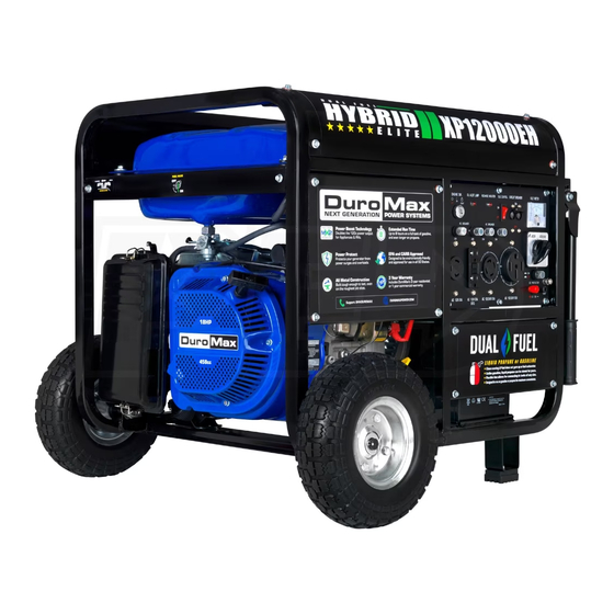
*Gasoline & Propane Tank Not Included
XP12000EH
S
E
R
V
I
C
E
M
A
N
U A
L
REV: XP12000EH-03162023
5800 Ontario Mills Pkwy
This manual provides information regarding the
Ontario, CA 91764 USA
operation and maintenance of these products. We
www.duromaxpower.com
have made every effort to ensure the accuracy of the
Call our Customer Care Team Toll Free 8-5 pm PST Mon-Fri
information in this manual. We reserve the right to
844-DUROMAX
change this product at any time without prior notice.
Advertisement
Table of Contents

Related Manuals for DUROMAX DUALFUEL XP12000EH


Summary of Contents for DUROMAX DUALFUEL XP12000EH
- Page 1 Call our Customer Care Team Toll Free 8-5 pm PST Mon-Fri information in this manual. We reserve the right to 844-DUROMAX change this product at any time without prior notice.
-
Page 3: Table Of Contents
CONTENTS Generator Components Generator Components ....................6 Maintenance and Care Maintenance Schedule ....................8 Break-In Period ....................... 9 High Altitude Operation ....................9 Changing the Carburetor Main Jet ................10 Checking the Oil ......................14 Changing the Oil ......................15 Cleaning the Air Filter .................... - Page 4 CONTENTS Generator Diagrams Common Engine Parts ....................39 Wiring Diagram ......................46 Maintenance Log Maintenance Log......................47...
-
Page 6: Generator Components
GENERATOR COMPONENTS 6. 120/240V 4-Prong 8. 120V 3-Prong 20. 120V 3-Prong Twist Lock Receptacle Twist Lock 2. Choke Lever 22. Idle Control 5. Circuit Breaker 10. Volt Meter 23. Power Boost 16. Fuel Valve 7. Ground Terminal 1. Air Filter 11. - Page 7 15. Fuel Filter Cup 3. Fuel Gauge 4. Fuel Cap 17. Spark Plug 18. Muffler 19. Propane Connector 13. Engine Switch – 3 Position Switch to “START”, “RUN”, or turn “OFF” the generator. 14. Recoil Start – Easy pull recoil start to start the engine without the electric start. 15.
-
Page 8: Maintenance And Care
MAINTENANCE AND CARE Proper routine maintenance of your generator is essential for safe, economical, and trouble-free operation. It will also help reduce air pollution. WARNING: Improper maintenance, or failure to correct a problem before operation, can cause a malfunction in which you can be seriously injured or killed. Always follow the inspection, maintenance recommendations, and schedules in this instruction manual. -
Page 9: Break-In Period
Operation at altitudes below 3,000 feet (900 meters) with a modified carburetor may cause the engine to overheat and result in serious engine damage. Note: Jet kits available for purchase upon request, please contact us at 844-DUROMAX to set up your parts order. -
Page 10: Changing The Carburetor Main Jet
MAINTENANCE AND CARE (CONTINUED) Changing the Carburetor Main Jet Unclip the cover and element Unclip and remove the air filter cover, then remove the air filter elements. NOTE: Carburetor should be drained of all gasoline prior to servicing. Unbolt element holder Remove all 6 bolts of the element holder with an 8mm socket wrench, then remove the element holder. - Page 11 Remove air filter hose Remove air filter hose clip with pliers and remove hose from behind air filter. Remove carburetor solenoid Remove both Phillips screws attaching carburetor solenoid with a standard Phillips screwdriver. Remove carburetor bowl bolt Remove the carburetor bowl bolt located under the solenoid with a 14 mm socket wrench.
- Page 13 MAINTENANCE AND CARE (CONTINUED) Changing the Carburetor Main Jet (Continued) Determine main jet location The carburetor jet is located inside the center metal tube of the carburetor. Remove main jet Remove the main jet with a flat head screwdriver. If necessary gently tap the carburetor to allow the jet and emulsion tube to fall out.
-
Page 14: Checking The Oil
MAINTENANCE AND CARE (CONTINUED) Checking the Oil Check the oil The generator is equipped with an automatic shutoff to protect it from damage due to low oil; nonetheless, you should check the oil level of the engine before each use to ensure that the engine crankcase has a sufficient amount. -
Page 15: Changing The Oil
Changing the Oil CAUTION: Worn out or dirty oil does not cool the generator properly and can lead to catastrophic engine damage. In addition to regular oil changes, it is necessary to drain the oil from the crankcase if it has become contaminated with water or dirt. -
Page 16: Cleaning The Air Filter
MAINTENANCE AND CARE (CONTINUED) Cleaning the Air Filter Routine maintenance of the air cleaner helps maintain proper airflow to the carburetor. Check that the air cleaner is free of excessive dirt after every use. CAUTION: Improper maintenance may cause less air to enter the engine or dirty air to enter the engine causing overheating and engine wear. - Page 17 Wash cleaner element Wash the sponge-like elements in household dish detergent and warm water. Dry cleaner element Pat dry on a dry cloth and allow the elements to dry completely. Add engine oil to elements Soak the dry elements in a small amount of engine oil. Ring out any excess oil.
-
Page 18: Spark Plug Maintenance
MAINTENANCE AND CARE (CONTINUED) Spark Plug Maintenance The spark plug is important for proper engine operation. SPARK PLUG A good spark plug should be intact, free of deposits, and CONSULT MANUAL properly gapped. BEFORE REMOVING CAUTION: Improper maintenance may cause reduced fuel economy, misfires, trouble starting, or damage to the spark plug threads. - Page 19 Measure plug gap Measure the plug gap with a gauge. The gap should be 0.7-0.8 mm (0.028-0.031 in). Clean and re-gap If you are re-using the spark plug, use a wire brush to clean any dirt from around the spark plug base and then re-gap the spark plug.
-
Page 20: Emptying The Gas Tank
MAINTENANCE AND CARE (CONTINUED) Emptying the Gas Tank If you have been using gasoline in your generator, before storing your generator for extended periods of time you should drain your generator fuel tank of gasoline. CAUTION: Do not store fuel from one season to another. - Page 21 Drain gas from the generator With a funnel underneath the fuel valve to catch the gas, turn the fuel valve to the “ON” position. Drain all the gas from the generator. Shut fuel valve OFF Turn the fuel valve to the “OFF” position. Replace fuel filter cup Reinstall the fuel filter cup.
-
Page 22: Cleaning The Fuel Filter Cup
MAINTENANCE AND CARE (CONTINUED) Cleaning the Fuel Filter Cup Shut fuel valve off Turn the fuel valve to the “OFF” position. Remove fuel filter cup Unscrew the fuel filter cup from the fuel valve using a wrench. Clean filter cup Clean the cup of all sediment using a rag or brush. -
Page 23: Transporting The Generator
Transporting the Generator Empty the gas tank Fully drain your gas tank as shown in “Emptying the Gas Tank” on page 20-21. Disconnect the spark plug Pull on spark plug cap to disconnect spark plug from ignition wire. CAUTION: Do not obstruct any ventilation openings and keep the generator in a cool dry area. -
Page 24: Storing The Generator For Same Day Use
MAINTENANCE AND CARE (CONTINUED) Storing the Generator for Same Day Use Turn the main breaker OFF Move the main breaker to the “OFF” position. Run the generator Allow the generator to run for 3-5 minutes. Turn the key switch OFF Turn the key switch counter-clockwise to the “OFF”... -
Page 25: Storing The Generator For Use Within 30 Days
Storing the Generator for Use Within 30 Days Turn breaker OFF and run Follow steps 1 and 2 as shown on “Storing the Generator For Same Day Use” on page 24. Shut fuel valve OFF and run dry Shut the fuel valve “OFF” and allow generator to run until it stalls out. -
Page 26: Storing The Generator For Longer Than 30 Days
MAINTENANCE AND CARE (CONTINUED) Storing the Generator for Longer Than 30 Days Turn breaker OFF and run Follow steps 1 and 2 as shown on “Storing the Generator For Same Day Use” on page 24. Shut fuel valve OFF and run dry Shut the fuel valve “OFF”... - Page 27 Drain the carburetor Remove drain bolt from carburetor and drain small amount of fuel in carburetor bowl. Remove spark plug Remove spark plug as shown in “Spark Plug Maintenance” on page 18. Add oil to cylinder Add 2 tablespoons of 10W-30 motor oil directly into the spark plug hole, and pull the recoil to lubricate cylinder.
-
Page 28: Check And Adjust Valve Clearance
MAINTENANCE AND CARE (CONTINUED) Check and Adjust Valve Clearance The engine intake and exhaust valve clearance should be checked and if necessary adjusted every 300 hours of use or 12 month period, whichever comes first. CAUTION: If the valve clearance isn’t maintained, this can cause the engine to run less efficiently and potentially cause engine damage. - Page 29 Set valves to top dead center Place screwdriver into spark plug hole to help determine the position of the piston, then slowly pull the recoil rope until the piston rises to the top position and both valves are closed (compression step). Check intake valve clearance The intake valve is on the right side of the cylinder head.
-
Page 30: Specifications
SPECIFICATIONS Model Number XP12000EH AC Rated Wattage (Gasoline) 9,500 W AC Rated Wattage (Propane) 9,025 W AC Surge Wattage (Gasoline) 12,000 W AC Surge Wattage (Propane) 11,400 W AC Rated Voltage 120/240V Dimensions 29”L x 30”W x 26”H Weight 224 lbs Recommended Oil 10W-30 Engine Displacement... -
Page 31: Torque Values
Torque Values Part Description Torque Value Oil Drain Bolt 18.5 ± 1.5 ft. lbs. (24 ± 2 N·m) Crankcase Cover Bolt 20.5 ± 1.5 ft. lbs. (28 ± 2 N·m) Flywheel Nut 70 ± 3 ft. lbs. (95 ± 4 N·m) Ignition Coil Bolt 7.5 ±... -
Page 33: Troubleshooting
TROUBLESHOOTING Problem Description Solution Engine switch is “OFF” Set engine switch to “ON” Fuel valve is “CLOSED” Turn the fuel valve to “OPEN” Choke is open Close the choke The engine is out of fuel Add fuel The engine will not Fuel is old or contaminated Change fuel start... -
Page 34: Changing/Inspecting The Carbon Brushes
TROUBLESHOOTING (CONTINUED) Changing/Inspecting the Carbon Brushes The carbon brushes in conjunction with the AVR regulates power from the generator. The carbon brushes are wearable parts and should be inspected every 250 running hours. Remove generator cover Remove the 2 bolts of the generator cover then pull the cover off the generator. - Page 35 Install new brush Install new carbon brush with bolt. Connect AVR wires Insert and connect the 2 wires from the AVR, be sure to connect + and – correctly. Replace generator cover Replace the back cover of the generator and secure it with the 2 bolts.
-
Page 36: Changing/Inspecting The Avr
TROUBLESHOOTING (CONTINUED) Changing/Inspecting the AVR The carbon brushes in conjunction with the AVR regulates power from the generator. If the generator is overheated or overloaded, the AVR may be damaged and require replacement. Remove generator cover Remove the 2 bolts of the generator cover then pull the cover off the generator. - Page 37 Disconnect wires from brush Remove the 2 wires from the AVR on the carbon brush. Install new AVR Install the new AVR with the 2 bolts. Reconnect wires to brush Insert and connect the 2 wires from the AVR, be sure to connect + and –...
- Page 38 TROUBLESHOOTING (CONTINUED) Changing/Inspecting the AVR (Continued) Replace generator cover Replace the back cover of the generator and secure it with the 2 bolts.
- Page 39 COMMON ENGINE PARTS Common Engine Parts 1. Flywheel Fan DJ188F-16002-A 2. Flywheel Assembly DJ192F-16200-G 3. Oil Seal 93512 4. Starter Motor Assembly DJ188F-18600-A 5. Crankcase Assembly 270203 6. Oil Drain Plug DJ188F-11004-A 7. Oil Sensor Amplifier 245104 8. Air Filter Assembly DJ192FD-14200 9.
- Page 40 COMMON ENGINE PARTS (CONTINUED) Common Engine Parts (Continued) 10. Breather Tube DJ188FD-11013-A 11. Valve Cover DJ188F-11300-B 12. Valve Cover Gasket DJ188F-11011-A 13. Spark Plug 97108 14. Cylinder Head Assembly 271005 15. Cylinder Head Gasket DJ192F-11010-C 16. Muffler/Cylinder Head Gasket DJ188F-14006-A 17.
- Page 41 22. Camshaft Assembly DJ192F-13100-C 23. Crankshaft Assembly DJ192F-12100-BB 24. Balancing Shaft Assembly DJ192F-12004-A 25. Crankcase Cover Gasket DJ192F-11003-B 26. Bearing GB276-89-6207 27. Crankcase Cover DJ190F-11001-B 28. Oil Cap/Dipstick 265604-295 29. Oil Seal 93512 30. Recoil Assembly 274727-072 31. Ignition Coil Assembly 97663...
- Page 42 COMMON ENGINE PARTS (CONTINUED) Common Engine Parts (Continued) 32. Air Filter/Carburetor Gasket DJ188F-14027-A 33. Propane Feed Hose 517914 34. Carburetor 272805 35. Carburetor/ Spacer Gasket DJ188F-14005-B 36. Spacer Gasket DJ192FD-14004-A 37. Gasoline Feed Hose 14034 38. Spacer/Cylinder Gasket DJ188F-14003-B 39. Throttle Return Spring DJ188F-15008-A 40.
- Page 43 45. Breather Valve 245405 46. Breather Valve Gasket DJ168F-14804-A 47. Fuel Valve Assembly 518614 48. Fuel Tank 700827-072 49. Fuel Filter 518801 50. Fuel Tank Cap 14306 51. Stator and Rotor Assembly 750041 52. Stator Support DF6500H-33005-A 53. Brush Assembly DF3800H-33001-A 54.
- Page 44 COMMON ENGINE PARTS (CONTINUED) Common Engine Parts (Continued) 57 58 59 60 61 62 56. Key Switch Assembly 34203-002 57. Main Circuit Breaker 6434-35 58. Voltage Meter 6416 59. 120V 30A Outlet 34204-002 60. 120V 20A GFCI Outlet 34204-007 61. 240V 30A Outlet 6241 62.
- Page 45 68. Wheel 523679 69. Cotter Pin 548201 70. Axle DF6500H-31018-I 71. Axle Nut GBT6187-N-12 72. Vibration Pad 531903 73. Support Leg DF6500H-31020-A 74. Handle Assembly 526901-010 75. Handle Grips 528601 76. Positive Battery Cable 512001 77. Battery 31110-Y9X0110-0000 78. Negative Battery Cable 512013 79.
- Page 46 WIRING DIAGRAM...
- Page 47 MAINTENANCE LOG Maintenance Log As a best practice it’s recommended to keep a log of the engine hours and maintenance to ensure your engine is always operating to its full potential. Date Engine Hours Maintenance Performed...
- Page 48 MAINTENANCE LOG (CONTINUED) Date Engine Hours Maintenance Performed...
- Page 49 Date Engine Hours Maintenance Performed...
- Page 50 MAINTENANCE LOG (CONTINUED) Date Engine Hours Maintenance Performed...
- Page 51 Date Engine Hours Maintenance Performed...
- Page 52 MAINTENANCE LOG (CONTINUED) Date Engine Hours Maintenance Performed...
- Page 54 5800 Ontario Mills Parkway Ontario, CA 91764 United States 844-DUROMAX REV: XP12000EH-03162023...