Table of Contents
Advertisement
Quick Links
SPLIT-TYPE, HEAT PUMP AIR CONDITIONERS
SPLIT-TYPE, AIR CONDITIONERS
SERVICE MANUAL
Indoor unit
[Model names]
PKA-A12GA
PKA-A18GA
PKA-A24FA
PKA-A30FA
PKA-A36FA
PKA-A12GAL
PKA-A18GAL
PKA-A24FAL
PKA-A30FAL
PKA-A36FAL
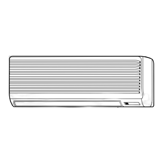
INDOOR UNIT
PKA-A12GA
PKA-A18GA
PKA-A12GAL PKA-A18GAL
TEMP.
ON/OFF
WIRED REMOTE
CONTROLLER
[Service Ref.]
PKA-A12GA
PKA-A12GA
PKA-A18GA
PKA-A18GA
PKA-A24FA
PKA-A24FA
PKA-A30FA
PKA-A30FA
PKA-A36FA
PKA-A36FA
PKA-A12GAL PKA-A12GAL
PKA-A18GAL PKA-A18GAL
PKA-A24FAL
PKA-A24FAL
PKA-A30FAL
PKA-A30FAL
PKA-A36FAL
PKA-A36FAL
Model name indication
WIRELESS REMOTE
CONTROLLER
PKA-A12GA
1
2
PKA-A18GA
1
2
PKA-A24FA
1
2
PKA-A30FA
1
2
PKA-A36FA
1
2
PKA-A12GAL
1
2
PKA-A18GAL
1
2
PKA-A24FAL
1
2
PKA-A30FAL
1
2
PKA-A36FAL
1
2
CONTENTS
1. TECHNICAL CHANGES ..................................... 2
2. REFERENCE MANUAL ...................................... 2
3. SAFETY PRECAUTION ...................................... 3
4. PART NAMES AND FUNCTIONS ....................... 5
5. SPECIFICATIONS ............................................... 9
6. NOISE CRITERION CURVES ........................... 11
7. OUTLINES AND DIMENSIONS ........................ 12
8. WIRING DIAGRAM ............................................ 15
9. REFRIGERANT SYSTEM DIAGRAM ................. 19
10. TROUBLE SHOOTING ...................................... 20
11. SPECIAL FUNCTION ......................................... 35
12. DISASSEMBLY PROCEDURE .......................... 38
13. RoHS PARTS LIST ............................................ 44
March 2013
No.OC369
REVISED EDITION-E
Revision:
• The indicated No. of
CORNER COVER (page
50) in the illustration have
been corrected in REVISED
EDITION-E.
• Please void OC369
REVISED EDTION-D.
NOTE:
• This manual describes only
service data of the indoor
units.
• RoHS compliant products
have <G> mark on the spec
name plate.
• For servicing RoHS compli-
ant products, refer to the
RoHS PARTS LIST.
Advertisement
Table of Contents

Related Manuals for Mitsubishi Electric PKA-A12GA


Summary of Contents for Mitsubishi Electric PKA-A12GA
-
Page 1: Table Of Contents
SPLIT-TYPE, AIR CONDITIONERS March 2013 No.OC369 REVISED EDITION-E SERVICE MANUAL Indoor unit Revision: [Model names] [Service Ref.] • The indicated No. of PKA-A12GA PKA-A12GA PKA-A12GA PKA-A12GA CORNER COVER (page 50) in the illustration have PKA-A18GA PKA-A18GA PKA-A18GA PKA-A18GA been corrected in REVISED EDITION-E. -
Page 2: Technical Changes
TECHNICAL CHANGES PKA-A12GA PKA-A12GA PKA-A18GA PKA-A18GA PKA-A24FA PKA-A24FA PKA-A30FA PKA-A30FA PKA-A36FA PKA-A36FA PKA-A12GAL PKA-A12GAL PKA-A18GAL PKA-A18GAL PKA-A24FAL PKA-A24FAL PKA-A30FAL PKA-A30FAL PKA-A36FAL PKA-A36FAL • Indoor controller board (I.B) has been changed (11. SPECIAL FUNCTION is added). PKA-A12GA PKA-A12GA PKA-A18GA PKA-A18GA PKA-A24FA... -
Page 3: Safety Precaution
SAFETY PRECAUTION 3-1. ALWAYS OBSERVE FOR SAFETY Before obtaining access to terminals, all supply circuits must be disconnected. 3-2. CAUTIONS RELATED TO NEW REFRIGERANT Cautions for units utilizing refrigerant R410A Use a vacuum pump with a reverse flow check Use new refrigerant pipes. valve. - Page 4 [2] Additional refrigerant charge When charging directly from cylinder · Check that cylinder for R410A on the market is syphon type. · Charging should be performed with the cylinder of syphon stood vertically. (Refrigerant is charged from liquid phase.) Unit Gravimeter [3] Service tools Use the below service tools as exclusive tools for R410A refrigerant.
-
Page 5: Part Names And Functions
PART NAMES AND FUNCTIONS Indoor Unit PKA-A12GA Filter Air intake grille PKA-A18GA Air intake PKA-A12GAL PKA-A18GAL PKA-A12GA PKA-A18GA PKA-A12GAL PKA-A18GAL PKA-A12GA PKA-A18GA PKA-A12GAL PKA-A18GAL Auto vane Guide vane Air outlet Indoor Unit PKA-A24FA PKA-A30FA PKA-A36FA Filter Air intake grille PKA-A24FAL Removes dust and dirt from the intake air. - Page 6 Wired remote controller Once the controllers are set, the same operation mode can be repeated by simply pressing the ON/OFF button. ON/OFF button Temperature setting buttons Down Fan Speed button Timer Menu button (Monitor/Set button) Filter button (<Enter> button) Mode button (Return button) Test Run button TEMP.
- Page 7 Wired remote controller Display Section Day-of-Week “Sensor” indication For purposes of this explanation, Shows the current day of the week. Displayed when the remote controller all parts of the display are shown. sensor is used. During actual operation, only Time/Timer Display the relevant items will be lit.
- Page 8 Wireless remote controller CHECK TEST RUN display Indicate that the unit is being checked or test-run. MODEL SELECT display display Blinks when model is selected. Lights up while the signal is transmitted to the indoor unit when the button is pressed. Temperature setting display Indicates the desired temperature setting which is set.
-
Page 9: Specifications
SPECIFICATIONS PKA-A12GA / PKA-A12GAL Service Ref. (1)(2) (1)(2) Single phase, 60Hz, 208/230V Power supply(phase, cycle, voltage) Max. Fuse Size Min. Circuit Ampacity External finish Munsell 0.70Y 8.59/0.97 Heat exchanger Plate fin coil Fan(drive) Line flow (direct) Fan motor output 0.030 Fan motor 0.33... - Page 10 Service Ref. PKA-A30FA / PKA-A30FAL (1)(2) (1)(2) Power supply (phase, cycle, voltage) Single phase, 60Hz, 208/230V Max. Fuse Size Min. Circuit Ampacity External finish Munsell 3.4Y 7.7/0.8 Heat exchanger Plate fin coil Fan (drive) Line flow (direct) Fan motor output 0.045 Fan motor 0.43...
-
Page 11: Noise Criterion Curves
NOISE CRITERION CURVES PKA-A12GA PKA-A12GA PKA-A24FA PKA-A24FA PKA-A12GAL PKA-A12GAL PKA-A30FA PKA-A30FA PKA-A18GA PKA-A18GA PKA-A24FAL PKA-A24FAL PKA-A18GAL PKA-A18GAL PKA-A30FAL PKA-A30FAL PKA-A12GA PKA-A24FA SPL(dB) LINE NOTCH PKA-A12GAL High PKA-A30FA NOTCH SPL(dB) LINE Medium1 PKA-A18GA PKA-A24FAL High Medium2 PKA-A18GAL PKA-A30FAL NC-70 NC-70 NC-60... -
Page 12: Outlines And Dimensions
OUTLINES AND DIMENSIONS INDOOR UNIT PKA-A12GA PKA-A18GA PKA-A12GAL PKA-A18GAL Unit :inch(mm) PKA-A12GA PKA-A18GA PKA-A12GAL PKA-A18GAL PKA-A12GA PKA-A18GA PKA-A12GAL PKA-A18GAL Right side 28-5/32(715) Air intake 8-27/32(225) Left side Front view 3-5/32(80) 13-3/8(340) 11-1/32(280) 9-3/16(233) Less than 19/32(15) Air intake Air intake Knockout hole for left piping Refrigerant pipe Drain pipe Wiring hole. - Page 13 INDOOR UNIT PKA-A24FA PKA-A30FA PKA-A24FAL PKA-A30FAL Unit :inch(mm) PKA-A24FA PKA-A30FA PKA-A24FAL PKA-A30FAL PKA-A24FA PKA-A30FA PKA-A24FAL PKA-A30FAL Top side 9-1/4(235) 9-1/4(235) 9-1/4(235) 9-1/4(235) 1-25/32(45) 1-25/32(45) 1-25/32(45) Right side Front view 55-1/8(1400) 9-1/4(235) Left side 42-29/32(1090) Air intake Knockout hole for right piping Terminal block Terminal block Knockout hole...
- Page 14 INDOOR UNIT PKA-A36FA PKA-A36FAL PKA-A36FA PKA-A36FAL Unit :inch(mm) PKA-A36FA PKA-A36FAL Top side 9-1/4(235) 9-1/4(235) 9-1/4(235) 9-1/4(235) 9-1/4(235) 1-25/32(45) 1-25/32(45) 1-25/32(45) 1-25/32(45) Right side Knockout hole Front view for right piping Left side 66-1/8(1680) 9-1/4(235) 53-15/16(1370) Air intake Knockout hole Terminal block Less than 9/16(15) for left piping Bolt...
-
Page 15: Wiring Diagram
WIRING DIAGRAM PKA-A12GA PKA-A18GA PKA-A12GAL PKA-A18GAL PKA-A12GA PKA-A18GA PKA-A12GAL PKA-A18GAL [LEGEND] SYMBOL NAME SYMBOL NAME SYMBOL NAME INDOOR POWER BOARD WIRELESS REMOTE CONTROLLER BOARD CAPACITOR<FAN MOTOR> INDOOR CONTROLLER BOARD FAN MOTOR RECEIVING UNIT BUZZER FUSE FUSE (6.3A/250V) VANE MOTOR LED1 VARISTOR TERMINAL BLOCK<INDOOR/OUTDOOR... - Page 16 PKA-A12GA PKA-A18GA PKA-A12GAL PKA-A18GAL [LEGEND] SYMBOL NAME SYMBOL NAME SYMBOL NAME INDOOR POWER BOARD LED2 POWER SUPPLY<R.B> WIRELESS REMOTE CONTROLLER BOARD INDOOR CONTROLLER BOARD LED3 TRANSMISSION<INDOOR-OUTDOOR> RECEIVING UNIT FUSE FUSE (6.3A/250V) BUZZER CAPACITOR<FAN MOTOR> VARISTOR FAN MOTOR LED1 LED<RUN INDICATOR >...
- Page 17 PKA-A24FA PKA-A30FA PKA-A36FA PKA-A24FAL PKA-A30FAL PKA-A36FAL PKA-A24FA PKA-A30FA PKA-A36FA PKA-A24FAL PKA-A30FAL PKA-A36FAL [LEGEND] SYMBOL NAME SYMBOL NAME SYMBOL NAME INDOOR POWER BOARD CAPACITOR<FAN MOTOR> WIRELESS REMOTE CONTROLLER BOARD INDOOR CONTROLLER BOARD FAN MOTOR RECEIVING UNIT FUSE FUSE (6.3A/250V) VANE MOTOR BUZZER VARISTOR TERMINAL BLOCK<INDOOR/OUTDOOR...
- Page 18 PKA-A24FA PKA-A30FA PKA-A36FA PKA-A24FAL PKA-A30FAL PKA-A36FAL [LEGEND] SYMBOL NAME SYMBOL NAME SYMBOL NAME INDOOR POWER BOARD LED2 POWER SUPPLY<R.B> WIRELESS REMOTE CONTROLLER BOARD LED3 TRANSMISSION<INDOOR-OUTDOOR> INDOOR CONTROLLER BOARD RECEIVING UNIT FUSE FUSE (6.3A/250V) CAPACITOR<FAN MOTOR> BUZZER VARISTOR FAN MOTOR LED1 LED<RUN INDICATOR >...
-
Page 19: Refrigerant System Diagram
REFRIGERANT SYSTEM DIAGRAM PKA-A12GA PKA-A18GA PKA-A24FA PKA-A30FA PKA-A36FA PKA-A12GAL PKA-A18GAL PKA-A24FAL PKA-A30FAL PKA-A36FAL PKA-A12GA PKA-A18GA PKA-A24FA PKA-A30FA PKA-A36FA PKA-A12GAL PKA-A18GAL PKA-A24FAL PKA-A30FAL PKA-A36FAL PKA-A12GA PKA-A18GA PKA-A24FA PKA-A30FA PKA-A36FA PKA-A12GAL PKA-A18GAL PKA-A24FAL PKA-A30FAL PKA-A36FAL Strainer Heat exchanger Refrigerant GAS pipe connection... -
Page 20: Troubleshooting
TROUBLESHOOTING 10-1. TROUBLESHOOTING <Error code display by self-diagnosis and actions to be taken for service (summary)> Present and past error codes are logged and displayed on the wired remote controller or controller board of outdoor unit. Actions to be taken for service and the trouble reoccurrence at field are summarized in the table below. Check the contents below before investigating details. - Page 21 10-2. MALFUNCTION-DIAGNOSIS METHOD BY REMOTE CONTROLLER <In case of trouble during operation> When a malfunction occurs to the air conditioner, both indoor unit and outdoor unit will stop and operation lamp blinks to inform unusual stop. < Malfunction-diagnosis method at maintenance service> [Procedure] 1.
- Page 22 • Refer to the following tables for details on the check codes. [Output pattern A] Beeper sounds Beep Beep Beep Beep Beep Beep Beep OPERATION · · · Repeated INDICATOR lamp blinking pattern Approx. 2.5 sec. 0.5 sec. 0.5 sec. 0.5 sec.
- Page 23 • On wireless remote controller The continuous buzzer sounds from receiving section of indoor unit. Blink of operation lamp • On wired remote controller Check code displayed in the LCD. • If the unit cannot be operated properly after the test run has been performed, refer to the following table to find out the cause. Symptom Cause Wired remote controller...
- Page 24 Note: Refer to the manual of outdoor unit for the details of display 10-3. SELF-DIAGNOSIS ACTION TABLE such as F, U, and other E. Abnormal point and detection method Countermeasure Error Code Cause 1 Defective thermistor 1–3 Check resistance value of thermistor. Room temperature thermistor (TH1) 1 The unit is in 3-minute resume characteristics...
- Page 25 Abnormal point and detection method Countermeasure Error Code Cause Freezing/overheating protection is (Cooling or drying mode) (Cooling or drying mode) operating 1 Clogged filter (reduced airflow) 1 Check clogs of the filter. 1 Freezing protection (Cooling mode) 2 Short cycle of air path 2 Remove blockage.
- Page 26 Abnormal point and detection method Countermeasure Error Code Cause Pipe temperature thermistor / 1 Defective thermistor 1–3 Check resistance value of thermistor. Condenser-Evaporator (TH5) characteristics 1 The unit is in 3-minute resume protec- 2 Contact failure of connector For characteristics, refer to (P1) above. 2 Check contact failure of connector (CN29) tion mode if short/open of thermistor is (CN29) on the indoor controller...
- Page 27 Abnormal point and detection method Countermeasure Error Code Cause 1 Contact failure, short circuit or, Indoor/outdoor unit communication * Check LED display on the outdoor control error (Signal receiving error) circuit board. (Connect A-control service miswiring (converse wiring) of 1 Abnormal if indoor controller board tool, PAC-SK52ST.) indoor/outdoor unit connecting cannot receive any signal normally for 6...
- Page 28 10-4. TROUBLESHOOTING OF PROBLEMS Note: Refer to the manual of outdoor unit for the detail of remote controller. Phenomena Cause Countermeasure (1)LED2 on indoor controller board • When LED1 on indoor controller board is also off. 1 Power supply of rated voltage is not supplied to out- 1 Check the voltage of outdoor power is off.
- Page 29 Note: Refer to the manual of the outdoor unit for the detail of remote controller. Phenomena Cause Countermeasure (1) LED2 on indoor controller board • When LED1 on indoor controller board is lit. 1 Check again the setting of refrigerant is off.
- Page 30 10-5. EMERGENCY OPERATION 10-5-1. When wireless remote controller has troubles or its battery is exhausted 1. Emergency operation is available in such a case using emergency operation switch equipped next to the receiver of indoor unit. 2. To start operation •...
- Page 31 10-6. HOW TO CHECK THE PARTS PKA-A12/ 18GA PKA-A24/ 30/ 36FA PKA-A12/ 18GAL PKA-A24/ 30/ 36FAL PKA-A12/ 18GA PKA-A24/ 30/ 36FA PKA-A12/ 18GAL PKA-A24/ 30/ 36FAL PKA-A12/ 18GA PKA-A24/ 30/ 36FA PKA-A12/ 18GAL PKA-A24/ 30/ 36FAL Parts name Check points Room temperature Disconnect the connector then measure the resistance with a tester.
- Page 32 10-7. TEST POINT DIAGRAM 10-7-1. Indoor controller board PKA-A12GA PKA-A18GA PKA-A24FA PKA-A30FA PKA-A36FA PKA-A12GAL PKA-A18GAL PKA-A24FAL PKA-A30FAL PKA-A36FAL PKA-A12GA PKA-A18GA PKA-A24FA PKA-A30FA PKA-A36FA PKA-A12GAL PKA-A18GAL PKA-A24FAL PKA-A30FAL PKA-A36FAL PKA-A12GA PKA-A18GA PKA-A24FA PKA-A30FA PKA-A36FA PKA-A12GAL PKA-A18GAL PKA-A24FAL PKA-A30FAL PKA-A36FAL LED1 LED2 CN22 Power supply (I.B)
- Page 33 10-7-2. Indoor power board PKA-A12GA PKA-A12GAL PKA-A12GA PKA-A12GAL PKA-A12GA PKA-A12GAL PKA-A18GA PKA-A18GAL PKA-A18GA PKA-A18GAL PKA-A18GA PKA-A18GAL PKA-A24FA PKA-A24FAL PKA-A24FA PKA-A24FAL PKA-A24FA PKA-A24FAL PKA-A30FA PKA-A30FAL PKA-A30FA PKA-A30FAL PKA-A30FA PKA-A30FAL PKA-A36FA PKA-A36FAL PKA-A36FA PKA-A36FAL PKA-A36FA PKA-A36FAL CN2S Connect to the indoor controller board (CN2D) between 1 to 3 12.6-13.7V DC (Pin1 (+))
- Page 34 PKA-A12,18GAL (1)(2) settings 1 2 3 4 5 PKA-A24,30,36FA (1)(2) PKA-A24,30,36FAL (1)(2) MODELS Service board 1 2 3 4 5 PKA-A12GA (1)(2) PKA-A12GAL (1)(2) 1 2 3 4 5 PKA-A18GA (1)(2) Capacity PKA-A18GAL (1)(2) settings 1 2 3 4 5...
-
Page 35: Special Function
SPECIAL FUNCTION 11-1. ROTATION FUNCTION (AND BACK-UP FUNCTION, 2ND STAGE CUT-IN FUNCTION) 11-1-1. Operation (1) Rotation function (and Back-up function) Outline of functions · Operating the unit of main and sub alternately according to the interval setting. (Rotation function) * The setting of main/sub unit depends on the refrigerant address. (The setting of dip switch on the outdoor unit) Refrigerant address "00"... - Page 36 11-1-2. How to perform the operation of rotation function (Back-up function, 2nd stage cut-in function) Set by wired remote controller. (Maintenance monitor) NOTE It is necessary to set the same content to both main unit and sub unit. Every time indoor controller board is replaced for servicing, it is necessary to set each function. (1) Request Code List Rotation setting Setting No.
- Page 37 (2) Setting method of each function by wired remote controller B: Refrigerant address C: Data display area D: Request code display area 1. Stop running the air-conditioner( ). 2. Press the TEST button ( ) for 3 seconds so that [Maintenance mode] appears on the screen (at After a while, [00] appears in the refrigerant address number display area.(at 3.
-
Page 38: Disassembly Procedure
DISASSEMBLY PROCEDURE PKA-A12GA PKA-A18GA PKA-A12GA PKA-A18GA PKA-A12GA PKA-A18GA PKA-A12GAL PKA-A18GAL PKA-A12GAL PKA-A18GAL PKA-A12GAL PKA-A18GAL OPERATION PROCEDURE PHOTOS & ILLUSTRATION Figure 1 Hook 1. REMOVING THE LOWER SIDE OF THE INDOOR UNIT FROM THE INSTALLATION PLATE (1) Remove the left / right corner box of the indoor unit. - Page 39 OPERATION PROCEDURE PHOTOS & ILLUSTRATION 4. REMOVING THE POWER BOARD Photo 4 (1) Remove the front panel. (See Photo 1) (2) Remove the electrical parts box (2 screws). (See Photo 2) Power board (3) Disconnect the whole connector in the control board. (4) After lifting the controller case with pressing its convex section, remove the controller case and the control board simultaneously.
- Page 40 OPERATION PROCEDURE PHOTOS & ILLUSTRATION 9. REMOVING THE FAN MOTOR Photo 9 (1) Remove the terminal block cover. Motor cover (2) Disconnect the connector <yellow> of the wireless remote controller board. (3) Remove the front panel. (See Photo 1) (4) Remove the electrical parts box. (See Photo 8) (5) Remove the nozzle assembly.
- Page 41 PKA-A24FA PKA-A30FA PKA-A24FAL PKA-A30FAL PKA-A36FA PKA-A36FAL PKA-A24FA PKA-A30FA PKA-A24FAL PKA-A30FAL PKA-A36FA PKA-A36FAL PKA-A24FA PKA-A30FA PKA-A24FAL PKA-A30FAL PKA-A36FA PKA-A36FAL OPERATING PROCEDURE PHOTOS & ILLUSTRATION 1. REMOVING THE LOWER SIDE OF THE INDOOR UNIT Figure 1 FROM THE INSTALLATION PLATE (1) Remove the 2 screws. Hanger of indoor unit Hang the indoor unit hangers to the catches on the instal- lation plate.
- Page 42 OPERATING PROCEDURE PHOTOS & ILLUSTRATION Relay (9) Remove the screws of the indoor controller board case, Photo 3 and pull out the indoor controller board case. Then the indoor power board, the fan motor capacitor Indoor and the heater relay can be serviced. Capacitor power board Indoor controller...
- Page 43 OPERATING PROCEDURE PHOTOS Screw 8. Removing the line flow fan and the fan motor Photo 7 Line flow fan (1) Remove the left and right side panels. Fan motor (2) Remove the grills. (3) Remove the electrical parts box. (4) Remove the drain pan. (5) Loosen the screw that fixes the line flow fan to the fan motor.
-
Page 44: Rohs Parts List
RoHS PARTS LIST ELECTRICAL PARTS PKA-A12GA PKA-A12GAL PKA-A12GA PKA-A12GAL PKA-A18GA PKA-A18GAL PKA-A18GA PKA-A18GAL Part number that is circled is not shown in the figure. Q'ty/set Wiring Recom- Remarks Parts No. Parts Name Specifications PKA-A12,18 Diagram mended (Drawing No.) Symbol Q'ty... - Page 45 RoHS PARTS LIST From the previous page Q'ty/set Wiring Recom- Remarks Specifications Parts No. Parts Name Diagram mended PKA-A12,18 (Drawing No.) Symbol Q'ty T7W E41 716 TERMINAL BLOCK 3P(L1, L2, GR) TERMINAL BLOCK 3P(S1, S2, S3) T7W E17 255 CAPACITOR ×...
- Page 46 RoHS PARTS LIST ELECTRICAL PARTS PKA-A24FA PKA-A30FA PKA-A24FAL PKA-A30FAL PKA-A24FA PKA-A30FA PKA-A24FAL PKA-A30FAL Part number that is circled is not shown in the figure. Q'ty/set Wiring Recom- PKA-A Remarks Part Name Diagram mended Part No. Specification (Drawing No.) 24 30 24 30 24 30 24 30 Symbol Q'ty BEARING MOUNT...
- Page 47 RoHS PARTS LIST From the previous page Q'ty/set Recom- Wiring PKA-A Remarks Part No. Part Name Specification Diagram mended (Drawing No.) 24 30 24 30 24 30 24 30 Symbol Q'ty T7W E35 313 INDOOR POWER BOARD 2P(1, 2) TERMINAL BLOCK 3P(S1, S2, S3) TERMINAL BLOCK T7W E41 716...
- Page 48 RoHS PARTS LIST ELECTRICAL PARTS PKA-A36FA PKA-A36FAL PKA-A36FA PKA-A36FAL Part number that is circled is not shown in the figure. Q'ty/set Wiring Recom- Remarks mended Part No. Part Name PKA-A36 Diagram Specification (Drawing No.) Q'ty Symbol BEARING MOUNT LEFT LINEFLOW FAN T7W H27 480 HEAT EXCHANGER T7W E25 529...
- Page 49 RoHS PARTS LIST From the previous page Q'ty/set Wiring Recom- Remarks Diagram mended Part No. Part Name Specification PKA-A36 (Drawing No.) Symbol Q'ty T7W E35 313 INDOOR POWER BOARD R01 E48 246 TERMINAL BLOCK 2P(1, 2) R01 E18 246 TERMINAL BLOCK 3P(S1, S2, S3) T7W E41 716 TERMINAL BLOCK...
- Page 50 RoHS PARTS LIST STRUCTURAL PARTS PKA-A12GA PKA-A12GA PKA-A18GA PKA-A18GA PKA-A12GAL PKA-A12GAL PKA-A18GAL PKA-A18GAL TEMP. ON/OFF Q'ty/set Wiring Recom- Remarks Parts Name Parts No. Specifications PKA-A12/18 Diagram mended (Drawing No.) Symbol Q'ty /GAL R01 08Y 808 BACK PLATE R01 08Y 658...
- Page 51 RoHS PARTS LIST STRUCTURAL PARTS PKA-A24FA PKA-A30FA PKA-A24FAL PKA-A30FAL PKA-A24FA PKA-A30FA PKA-A24FAL PKA-A30FAL TEMP. ON/OFF Part number that is circled is not shown in the figure. Q'ty/set Wiring Recom- Remarks Part No. PKA-A24/30 Part Name Specifications Diagram mended (Drawing No.) Symbol Q'ty /FAL...
- Page 52 RoHS PARTS LIST STRUCTURAL PARTS PKA-A36FA PKA-A36FAL PKA-A36FA PKA-A36FAL TEMP. ON/OFF Part number that is circled is not shown in the figure. Q'ty/set Wiring Recom- Remarks PKA-A36 Diagram mended Part Name Specification Part No. (Drawing No.) Symbol Q'ty /FAL LEFT SIDE PANEL UNDER PLATE NOSE R01 A17...
- Page 53 OC369E...
- Page 54 HEAD OFFICE : TOKYO BLDG., 2-7-3, MARUNOUCHI, CHIYODA-KU, TOKYO 100-8310, JAPAN CCopyright 2006 MITSUBISHI ELECTRIC CORPORATION Distributed in Mar. 2013 No.OC369 REVISED EDITION-E Distributed in Apr. 2009 No.OC369 REVISED EDITION-D PDF 7 Distributed in Oct. 2007 No.OC369 REVISED EDITION-C PDF 9 Distributed in Jun.