Table of Contents
Advertisement
Quick Links
Quick Installation Guide
SBC-776
Intel FC-PGA 370-pin Pentium III with LCD, Audio, Compact flash,
Ultra II Wide SCSI, LAN, 2 COMs, & 4 USB
Notice:
This guide is designed for experienced users to
setup the system within the shortest time. For
detailed information, please always refer to the
electronic user's manual.
Safety Precautions
Warning! Always completely disconnect the power cord
from your chassis whenever you work with the
hardware. Do not make connections while the
power is on. Sensitive electronic components can
be damaged by sudden power surges. Only
experienced electronics personnel should open
the PC chassis.
Caution!
Always ground yourself to remove any static
charge before touching the CPU card. Modern
electronic devices are very sensitive to static
electric charges. As a safety precaution, use a
grounding wrist strap at all times. Place all
electronic components in a static-dissipative
surface or static-shielded bag when they are not
in the chassis.
Part no. 2007077600 1st Ed. Printed in Taiwan Dec. 2000
SBC-776 Installation Guide
1
Advertisement
Table of Contents

Related Manuals for Aaeon SBC-776


Summary of Contents for Aaeon SBC-776
- Page 1 As a safety precaution, use a grounding wrist strap at all times. Place all electronic components in a static-dissipative surface or static-shielded bag when they are not in the chassis. Part no. 2007077600 1st Ed. Printed in Taiwan Dec. 2000 SBC-776 Installation Guide...
- Page 2 VGA or AGP VGA Select Header Clear CMOS Selection Watchdog Function Select RS-232/422/485 COM 2 Setting DiskOnChip Address Selection Function Select CPU/DIMM Speed Select LCD Panel's Voltage Setting RS-232/422/485 COM2 Setting JP10 LCD or VGA Enable Header BC-599/596 SBC-776 Installation Guide...
- Page 3 ATX Power Supply CN24 Speaker/Buzzer CN25 System FAN 1 Connector CN26 CPU Fan Connector CN27 System FAN 2 Connector CN28 LCD Backlight Power Connector CN29 TFT LCD Panel Connector CN31 PS/2 Keyboard Header CN32 PS/2 Mouse Header SBC-776 Installation Guide...
-
Page 4: Locating Jumpers And Connectors
SBC-776 Locating Jumpers and Connectors CN24 JP10 CN12 CN28 CN29 CN30 CN10 CN33 CN21 CN11 CN32 BC-599/596 SBC-776 Installation Guide... - Page 5 Quick Installation Guide Locating Jumpers and Connectors SBC-776 Installation Guide...
-
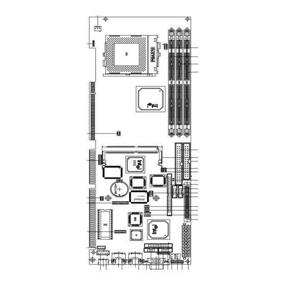
Page 6: Mechanical Drawing
SBC-776 Mechanical Drawing BC-599/596 SBC-776 Installation Guide... - Page 7 Quick Installation Guide Mechanical Drawing SBC-776 Installation Guide...
-
Page 8: Vga Or Agp Vga Header Select (Jp 1)
You can use JP2 to clear the CMOS data if necessary. To reset the CMOS data, place a jumper on JP2 for just a few seconds, then remove the jumper. Clear CMOS (J2P) Clear CMOS Protect 1 2 3 1 2 3 *default BC-599/596 SBC-776 Installation Guide... - Page 9 The mainboard is equipped with a watchdog timer that resets the CPU or generates an interrupt if processing comes to a standstill for whatever reason. This feature ensures system reliability in industrial stand-alone and unmanned environments. Reset IRQ15 SBC-776 Installation Guide...
- Page 10 SBC-776 RS-232/422/485 COM 2 (JP4 &JP9) Setting The SBC-776 COM 2 serial port can be selected as RS-232/422/485 by setting JP4. *RS-232 3 6 9 12 2 4 6 1 3 5 1 4 7 10 *RS-485 3 6 9 12...
- Page 11 JP5 controls the memory address of the Flash Disk. *D400H 1 3 5 2 4 6 *DC00H 1 3 5 2 4 6 *CE00H 1 3 5 2 4 6 *D000H 1 3 5 2 4 6 SBC-776 Installation Guide...
- Page 12 *D800H 1 3 5 2 4 6 *C800H 1 3 5 2 4 6 These addresses might conflict with the ROM BIOS of other peripheral boards, Please select the appropriate memory address to avoid memory conflicts. BC-599/596 SBC-776 Installation Guide...
-
Page 13: Function Select Header (Jp 6)
Speaker The mainboard can drive an 8Ω external speaker at 0.5 watts. If there is no external speaker, the SBC-776 provides an onboard buzzer as an alternative. LED interface The front panel LED indicator for hard disk access is an active low signal (24 mA sink rate). -
Page 14: Cpu/Dimm Speed Select Header (Jp 7)
SBC-776 CPU/DIMM Speed Select Header (JP 7) CPU/133 DIMM/133 CPU/133 DIMM/100 CPU/100 DIMM/100 CPU/66 DIMM/100 BC-599/596 SBC-776 Installation Guide... - Page 15 Quick Installation Guide Auto Detect Default SBC-776 Installation Guide...
-
Page 16: Lcd Panel's Voltage Setting (Jp 8)
*LCD Panel power: +5V; Backlight power: +12V 1 3 5 2 4 6 *LCD Panel power: +3.3V; Backlight power: +5V 1 3 5 2 4 6 *LCD Panel power: +3.3V; Backlight power: +12V 1 3 5 2 4 6 BC-599/596 SBC-776 Installation Guide... -
Page 17: Lcd Or Vga Enable Header (Jp10)
CN6 is a 15-pin, dual-in-line header used for conventional CRT displays. A simple one-to-one adapter can be used to match CN6 to a standard 15-pin D-SUB connector commonly used for VGA. VGA display connector (CN6) Signal Signal GREEN BLUE DDDA H-SYNC V-SYNC DDCK SBC-776 Installation Guide... -
Page 18: Ide Hard Drive Connector (Cn7)
DATA 0 DATA 15 SIGNAL GND IDEPDREQR IO WRITE IO READ IO CHANNEL READY 28 IDEPDACKX IRQ14 IOCS16 ADDR 1 P66DET ADDR 0 ADDR 2 HARD DISK SELECT 0 HARD DISK SELECT 1 IDE ACTIVE MGND BC-599/596 SBC-776 Installation Guide... -
Page 19: Usb Connector (Cn9, Cn10)
Quick Installation Guide USB connector (CN9, CN10) The SBC-776 provides two USB (Universal Serial Bus) interfaces, which give complete plug and play, hot attach/detach for up to 127 external devices. The USB interfaces comply with USB specifica- tion Rev. 1.0, and can be disabled in the system BIOS setup. -
Page 20: Audio Connector (Cn11)
SBC-776 Audio Connector (CN11) On board SBC-776, there is a 14-pin header for audio capability. The pin definition is provided below. Audio connector (CN 11) Signal Signal MIC IN MIC VCC CD IN GND LINE IN L CD IN L I/P... -
Page 21: Floppy Drive Connector (Cn12)
Floppy drive connector (CN12) Signal Signal DENSITY SELECT DRIVE TYPE INDEX MOTOR 0 DRIVE SELECT 1 DRIVE SELECT 2 MOTOR 1 DIRECTION STEP WRITE DATA WRITE GATE TRACK 0 WRITE PROTECT READ DATA HEAD DELECT DISK CHANGE SBC-776 Installation Guide... -
Page 22: Parallel Port Irq
Parallel port connector (CN14) Normally, the parallel port is used to connect the board to a printer. The SBC-776 includes an onboard parallel port, accessed through CN14, a 26-pin flat-cable connector. A traditional DB-25 connector cable is needed to install the printer to the board. The cable has a 26-pin connector on one end and a DB-25 connector on the other. - Page 23 Two of them are the D-Sub type, pin definition show as below, for another two, please refer to page ?. COM 1 RS-232 (CN15) Signal Signal SDCDB1X SDSRB1X SRXDB1 SRTSB1X STXDB1 SCTSB1X SDTRB1X SRIB1X COM 1 RS-232 (CN16) Signal Signal SDCDB2X SDSRB2X SRXDB2 SRTSB2X STXDB2 SCTSB2X SDTRB2X SRIB2X SBC-776 Installation Guide...
- Page 24 SBC-776 SCSI-2 68-PinConnector (CN 21) SBC-776 has a 68 pin connector for the Ultra 2 SCSI connection. Please pay attention when connecting the SCSI device, because you must determine the last device on the SCSI chain. FUNCTION FUNCTION SD+12 SD-12...
- Page 25 * The on board Intel 82559XX fast ethernet controller supports 10Mb/s and 100Mb/s N-way auto-negotiation operation. Green LED: 100M LAN speed Yellow LED: 10M LAN speed 100Base-Tx Ethernet connector (CN22) Signal Green LED: 100M LAN speed Yellow LED: 10M LAN speed 100Base-Tx Ethernet connector (CN20) Signal SBC-776 Installation Guide...
- Page 26 -12V POWER ON +5 V POWER OK +5VSB +12V Speaker/Buzzer (CN 24) You can choose to use the internal buzzer on the SBC-776 baord, or you may use your own external speaker. Speaker/Buzzer (CN24) Speaker On Board Buzzer CN24 BC-599/596...
- Page 27 Plug in the fan cable to the 3-pin fan connector onboard. The fan connector is marked CN26. CPU fan power connector (CN26) Signal +12V Fan speed sensor System fan 1 connector (CN 25) Signal +12V Fan speed sensor System fan 2 connector (CN27) Signal +12V Fan speed sensor SBC-776 Installation Guide...
-
Page 28: Lcd Backlight Power Connector (Cn 28)
LCD Backlight Power Connector (CN 28) LCD Backlight Power Connector (CN 28) Signal BLKVCC TFT LCD panel connector (CN 29) LCD panel connector (CN 29) Signal Signal BLKVCC BLKVCC LDCVCC LCDVCC ENA VEE SHF CLK VSYNC HSYNC FPBLEN BC-599/596 SBC-776 Installation Guide... -
Page 29: Ps/2 Keyboard Header (Cn31)
Signal Signal KB CLOCK KB DATA PS/2 Mouse Header (CN 32) Onboard there is a 4-pin header for keyboard connection, the pin definition is provided below. PS/2 Mouse Header (CN 32) Signal Signal MS CLOCK MS DATA SBC-776 Installation Guide... - Page 30 SBC-776 BC-599/596 SBC-776 Installation Guide...