
Related Manuals for N.A.T. powerBridge NAMC-EXT

Summary of Contents for N.A.T. powerBridge NAMC-EXT
- Page 1 NAMC-EXT – Technical Reference Manual NAMC-EXT NAMC-EXT-PS AMC Extender Module Technical Reference Manual V1.6 HW Revision 1.5...
- Page 2 NAMC-EXT – Technical Reference Manual The NAMC-EXT has been designed by: N.A.T. GmbH Konrad-Zuse-Platz 9 D-53227 Bonn-Oberkassel Phone: ++49 / 228 / 965 864 - 0 Fax: ++49/ 228 / 965 864 - 10 Internet: http://www.nateurope.com Version 1.6 © N.A.T. GmbH...
- Page 3 NAMC-EXT – Technical Reference Manual Disclaimer The following documentation, compiled by N.A.T. GmbH (henceforth called N.A.T.), represents the current status of the product´s development. The documentation is updated on a regular basis. Any changes which might ensue, including those necessitated by updated specifications, are considered in the latest version of this documentation.
-
Page 4: Table Of Contents
NAMC-EXT – Technical Reference Manual Table of Contents TABLE OF CONTENTS ..................4 LIST OF TABLES ....................5 LIST OF FIGURES ....................5 CONVENTIONS ....................6 INTRODUCTION ................... 7 OVERVIEW ....................9 ..................9 LOCK IAGRAM ..................10 OCATION IAGRAM .....................12 IMENSIONS BOARD FEATURES .................. -
Page 5: Table Of Contents
NAMC-EXT – Technical Reference Manual List of Tables Table 1: List of used abbreviations ..............6 Table 2: AMC Port Definition for N.A.T. AMC Modules ..........14 Table 3: J1/JP1: AMC Connectors – Pin Assignment ..........16 Table 4: Wire Bridges ..................19 Table 5: NAMC-EXT: Board Specifications ............20 List of Figures... -
Page 6: List Of Tables
NAMC-EXT – Technical Reference Manual Conventions If not otherwise specified, addresses and memory maps are written in hexadecimal notation, identified by 0x. The following table gives a list of the abbreviations used in this document. Table 1: List of used abbreviations Abbreviation Description Advanced Mezzanine Card... -
Page 7: Introduction
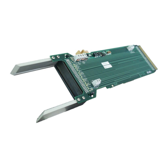
NAMC-EXT – Technical Reference Manual 1 Introduction The NAMC-EXT is an extender card for standard AMCs, single width, double height. It can be plugged onto any ATCA carrier board supporting AMC standards. It is also designed to meet the requirements of μTCA systems. It eases debugging of AMC boards by enabling the user to access the module under test from both sides, install debug port cables, and allow access for measurement of power supplies. -
Page 8: Figure 2: Mechanical Installation In A Chassis
NAMC-EXT – Technical Reference Manual Mechanical installation of the NAMC-EXT is shown in the figure below. Figure 2: Mechanical Installation in a Chassis For detailed information about the dimensions of the NAT-EXT, please refer to chapter 2.3. Version 1.6 © N.A.T. GmbH... -
Page 9: Overview
NAMC-EXT – Technical Reference Manual 2 Overview The NAMC-EXT is a passive extender board, it does not contain any circuitry. The NAMC-EXT-PS features an on-board +3.3V power supply for generating Management Power from Payload Power, so the module under test can be operated with an external +12V power supply only. -
Page 10: Location Diagram
NAMC-EXT – Technical Reference Manual 2.2 Location Diagram The following figures highlight the position of the important components. Depending on the board type it might be that the board does not include all components named in the location diagrams. This applies in particular to the optional +3.3V power supply of the NAMC-EXT-PS. -
Page 11: Figure 5: Namc-Ext - Location Diagram (Bottom Left Side)
NAMC-EXT – Technical Reference Manual Figure 5: NAMC-EXT – Location Diagram (bottom left side) Version 1.6 © N.A.T. GmbH... -
Page 12: Dimensions
NAMC-EXT – Technical Reference Manual 2.3 Dimensions The main function of the NAMC-EXT is to allow access for measuring and debugging purposes to a standard AMC. Hence connector JP1 (that picks up the AMC) and all measuring points are located on the extended part outside the chassis. To allow this it is inevitable that the extended area varies from the outlines defined in the AMC.0 specification, whereas the part that fits into the chassis still complies with the defined dimensions. -
Page 13: Figure 6: Namc-Ext - Dimensions
NAMC-EXT – Technical Reference Manual Figure 6: NAMC-EXT – Dimensions Version 1.6 © N.A.T. GmbH... -
Page 14: Board Features
NAMC-EXT – Technical Reference Manual 3 Board Features 3.1 Bus Interface All AMC ports connected 3.2 Power Supply The NAMC-EXT draws very little power from the carrier supplies. Current drawn from +3.3V and +12V is less than 10mA each. Power planes for GND, payload power and management power. Both power supplies drive signalling LEDs. -
Page 15: Hardware
NAMC-EXT – Technical Reference Manual 4 Hardware 4.1 AMC Port Definition Table 2: AMC Port Definition for N.A.T. AMC Modules Port # Port Mapping Port used as Strategy CLK1 Universal Clock Signal, depends on used AMC Clocks CLK2 Universal Clock Signal, depends on used AMC CLK3 Universal Clock Signal, depends on used AMC Common... -
Page 16: Connectors, Jumpers And Wire Bridges
NAMC-EXT – Technical Reference Manual 4.2 Connectors, Jumpers and Wire Bridges There are 2 connectors and 3 wire bridges on the NAMC-EXT. Connector J1 is a direct connector and fits into the ATCA or TCA AMC slot. Connector JP1 is the socket into which the device under test is plugged. -
Page 17: J1/Jp1: Amc Connectors
NAMC-EXT – Technical Reference Manual 4.2.1 J1/JP1: AMC Connectors Table 3: J1/JP1: AMC Connectors – Pin Assignment Pin # AMC-Signal AMC-Signal Pin # /PS1 PWR_IPMB /TRST RESVD RESVD Tx20+ Tx20- Tx0+ Rx20+ Tx0- Rx20- Rx0+ Tx19+ Rx0- Tx19- Rx19+ Rx19- Tx1+ Tx18+ Tx1-... - Page 18 NAMC-EXT – Technical Reference Manual Pin # AMC-Signal AMC-Signal Pin # Rx4+ Rx14+ Rx4- Rx14- Tx5+ Tx13+ Tx5- Tx13- Rx5+ Rx13+ Rx5- Rx13- IPMB_SCL Tx12+ Tx12- Tx6+ Rx12+ Tx6- Rx12- Rx6+ Tx11+ Rx6- Tx11- Tx7+ Rx11+ Tx7- Rx11- Rx7+ Tx10+ Rx7- Tx10- IPMB_SDA...
-
Page 19: Jumper Jp2
NAMC-EXT – Technical Reference Manual 4.2.2 Jumper JP2 The setting of jumper JP2 defines the source for /AMC_ENABLE signal. The default position (right aligned) means the signal is connected to the backplane. In the left aligned position the signal is pulled down locally on the extender board. 4.2.3 Jumper JP3 (NAMC-EXT-PS only) The setting of jumper JP3 defines the source of Management Power. -
Page 20: Wire Bridges
NAMC-EXT – Technical Reference Manual 4.2.4 Wire Bridges The wire bridges BR1 and BR2 connect the supply voltages. The supply current can be measured between both contacts of one bridge if the respective wire bridge is opened. Please note: Instead of using a simple ampere meter it is recommended to insert a shunt resistor (e.g. -
Page 21: Board Specifications
NAMC-EXT – Technical Reference Manual 5 Board Specifications Table 5: NAMC-EXT: Board Specifications AMC-Module Extender for Standard Advanced Mezzanine Cards, single width, double height Power Consumption +3.3V / 0.01A typical +12V / 0.01A typical (NAMC-EXT only) Operating Temperature -40°C - +85°C Storage Temperature -40°C - +85°C Humidity... -
Page 22: Installation
NAMC-EXT – Technical Reference Manual 6 Installation 6.1 Safety Note To ensure proper functioning of the NAMC-EXT during its usual lifetime take the following precautions before handling the board. CAUTION Electrostatic discharge and incorrect board installation and uninstallation can damage circuits or shorten their lifetime. -
Page 23: Statement On Environmental Protection
NAMC-EXT – Technical Reference Manual 6.3 Statement on Environmental Protection 6.3.1 Compliance to RoHS Directive Directive 2011/65/EU of the European Parliament and of the Council of 8 June 2011 on the "Restriction of the use of certain Hazardous Substances in Electrical and Electronic Equipment"... -
Page 24: Compliance To Ce Directive
NAMC-EXT – Technical Reference Manual If you have any questions on the policy of N.A.T. regarding the Directive 2011/65/EU of the European Parliament and of the Council of 8 June 2011 on the "Restriction of the use of certain Hazardous Substances in Electrical and Electronic Equipment"... -
Page 25: Known Bugs / Restrictions
NAMC-EXT – Technical Reference Manual 7 Known Bugs / Restrictions none Version 1.6 © N.A.T. GmbH... -
Page 26: Appendix A: Document's History
NAMC-EXT – Technical Reference Manual Appendix A: Document’s History Revision Date Description Author 05.01.2007 initial revision 14.03.2007 adapted to HW Release 1.3 and to AMC Spec R. 2.0 02.05.2007 adapted to HW Release 1.4 26.06.2007 altered naming of signals to be board-independent 10.06.2008 adapted to HW Release 1.5 14.11.2011...