Table of Contents
Advertisement
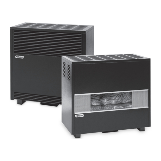
OWNER'S MANUAL
INSTALLATION INSTRUCTIONS
VENTED ROOM HEATERS
ENCLOSED FRONT MODEL NUMBERS (natural gas)
2001622A
/
3501522A
5001922A
/
6501522A
ENCLOSED FRONT MODEL NUMBERS (propane gas)
2001621A
/
3501521A
/
5001921A
/
6501521A
/
FIREPLACE FRONT MODEL NUMBERS (natural gas)
3502522A
/
3502922A
5002922A
/ 6502522A /
FIREPLACE FRONT MODEL NUMBERS (propane gas)
3502521A
/
3502921A
/ 5002521A
5002921A /
6502521A
SAVE THIS MANUAL FOR FUTURE REFERENCE.
READ THIS OWNER'S MANUAL CAREFULLY BEFORE YOU
INSTALL YOUR NEW WILLIAMS WALL FURNACE.
WARNING: Do not install any of these furnaces
(natural or propane gas) in mobile/manufactured homes,
trucks or recreational vehicles.
WARNING: This product can expose you to
chemicals including epichlorohydrin which is known to
the State of California to cause cancer and birth defects
and/or other reproductive harm. For information go to
www.p65warnings.ca.gov
WARNING: Improper installation, adjustment,
alteration, service or maintenance can cause injury or
property damage. Refer to this manual. For assistance or
for additional information consult a qualified installer or,
service agency.
250 West Laurel Street, Colton CA 92324 • WWW.WFC-FC.COM • 1-888-444-1212
TM
/
3501922A
/
5001522A
/
6501922A
3501921A
/
5001521A
6501921A
/
5002522A
6502922A
/
6502921A
VISITEZ NOTRE SITE WEB POUR LA VERSION FRANÇAISE DE CE MANUEL
VISITE NUESTRA PÁGINA WEB PARA LA VERSIÓN EN ESPAÑOL DE ESTE MANUAL
https://www.williamscomfortprod.com/products/furnaces/
ENCLOSED
MODEL
WARNING: If the information in these instructions
is not followed exactly, a fire or explosion may result
causing property damage, personal injury or loss of life.
- Do not store or use gasoline or other flammable vapors
and liquids in the vicinity of this or any other appliance.
WHAT TO DO IF YOU SMELL GAS:
• Open all windows.
• Do not try to light any appliance.
• Do not touch any electrical switch; do not use
any phone or cell phone in your building.
• Extinguish any open flame.
• Immediately call your gas supplier from a neighbor's
phone. Follow the gas supplier's instructions.
• If you cannot reach the gas supplier, call the fire
department.
– Installation and service must be performed by a
qualified installer, service agency or the gas supplier.
FIREPLACE
MODEL
Advertisement
Table of Contents

Related Manuals for Williams 3501522A


Summary of Contents for Williams 3501522A
- Page 1 FIREPLACE READ THIS OWNER’S MANUAL CAREFULLY BEFORE YOU MODEL INSTALL YOUR NEW WILLIAMS WALL FURNACE. WARNING: If the information in these instructions is not followed exactly, a fire or explosion may result causing property damage, personal injury or loss of life.
-
Page 2: Your Williams Warranty
WARRANTY The manufacturer, Williams Furnace Co., warrants this wall furnace Some states do not allow limitation on how long an implied or heater to the original purchaser under the following conditions: warranty lasts, and some states do not allow the exclusion or... -
Page 3: Table Of Contents
CONTENTS Quick reference, YOUR WILLIAMS WARRANTY here’s how to: INSTALLATION RECORD INSTALLING YOUR FURNACE TABLE OF CONTENTS Furnace locations SAFETY RULES OPERATING YOUR FURNACE Igniting your furnace for the first time. INTRODUCTION INSTALLING YOUR FURNACE CARING FOR YOUR HEATER Learn how to keep your new BASIC MATERIALS NEEDED Williams Furnace operating. -
Page 4: Safety Rules
SAFETY RULES 9. Install the furnace vent directly to the outdoors, so WARNING: Read these rules and the instructions that harmful gases will not collect inside the building. carefully. Failure to follow these rules and instructions Follow the venting instructions for your type of could cause a malfunction of the furnace. -
Page 5: Introduction
INTRODUCTION Please read our instructions before you install and use Combustion air is drawn in from the room where the your heater. This will help you obtain the full value from heater is located and is vented out of the heater vertically this heater. -
Page 6: Installing Your Furnace
INSTALLING YOUR FURNACE Basic Tools Needed Unpacking Your Heater Hand drill or properly grounded electric drill Examine all packing material carefully. Look for loose parts before discarding. Store all parts where they cannot 1/8 inch and 3/16 inch drill bit (metal) ... - Page 7 Optional floor boards are available from Williams. 7. Do not place the heater where curtains, draperies, or any other material may come into contact with any part of the heater.
- Page 8 INSTALLING YOUR FURNACE NOTE: Minimum fresh air opening is 1 square inch FIGURE 2 - LEFT SIDE GAS INLET per 1,000 BTU/hr. GAS PIPING State and local authorities have established codes regulating the installation of gas burning equipment. Consult your gas supplier or gas company for complete information.
-
Page 9: Combustion & Ventilation Air
FIGURE 4 - ENCLOSED MODEL fuel burning appliances. Any use of appliances that pull air out of the house (clothes dryers, exhaust fans, fireplaces, etc.) increases this problem and appliances could be starving for air. In addition, these energy measures mean that your home will retain more water vapor or a higher relative humidity. -
Page 10: Installing Your Furnace
INSTALLING YOUR FURNACE If you have kitchen and bathroom exhaust fans, turn LOUVERS / GRILLES AND SCREENS COVERING them off and check for spillage. FREE AREA OPENINGS If spillage stops, do not use exhaust fans until you If a screen is used to cover the opening(s), it must not be can supply fresh air by a permanent duct. - Page 11 Refer to figure as shown on page 11, Figure. 9, which shows WARNING: Danger of property damage, bodily grille installation. Using the previous example, the two injury or loss of life. The adjoining unconfined space connecting rooms plus the closet must equal at least 500 must have adequate air infiltration as defined in sq.
-
Page 12: Thermostat Installation
(Sold Separately) appearance, fasten the thermostat base to the wall through the mounting holes with screws provided. Williams’ heaters are operated by a millivolt type thermostat. Current to the thermostat is supplied by the Replace the thermostat cover. pilot generator. Do not connect to electricity. Anticipator Do not run wire in any location where it might be settings are not required. - Page 13 Vent Installation taping lightly with a screwdriver. It will also be necessary to cut the inside panel insulation about a ½-inch in diameter for clearance to the knockout. Cut the thermostat wire to the desired length. This heater must be properly connected to a venting system. This heater is equipped with a vent safety shutoff system to protect Connect the thermostat wires to the terminal screws against improper venting of combustion products.
-
Page 14: Typical Methods Of Safely Venting The Heater
INSTALLING YOUR HEATER 3. Use vent pipe of the same size as the outlet on back enclosure is recommended. Use type B, vent pipe and of heater. In no case should a different size vent maintain at least a one inch clearance to combustibles. be used. - Page 15 FIGURE 16 - VENTING INTO AN OUTSIDE FIGURE 14 - VENTING INTO A MASONRY CHIMNEY TYPE “B” GAS VENT FIGURE 16 B - ALTERNATE VENTING FIGURE 15 - STRAIGHT UP VENTING WITH TYPE “B” GAS VENT VENTED ROOM HEATERS...
-
Page 16: Start-Up Procedure
OPERATING YOUR HEATER Start-Up Procedure CHECK THE GAS INPUT (NATURAL GAS ONLY) Start the heater using the procedures in the section “Operating Your Heater”. WARNING: Natural gas heating value (BTU per cubic foot) can vary significantly. Therefore, it is the WARNING: Danger of bodily injury or death. -
Page 17: For Your Safety
FIGURE 18 - BURNER FLAME CHARACTERISTICS WARNING: Natural gas heating value (BTU per cubic foot) can vary significantly; therefore, it is the installer’s responsibility to see that the BTU input to the heater is adjusted properly. Failure to do so could cause combustion chamber failure, asphyxiation, fire or explosion, resulting in property damage, bodily injury or death. - Page 18 OPERATING YOUR HEATER Use only your hand to push in or turn the gas control • If the pilot will not stay lit after several tries, turn the knob. Never use tools. If the knob will not push in or gas control knob to “OFF”...
-
Page 19: Caring For Your Heater
CARING FOR YOUR HEATER HEATER AREA WARNING: DUE TO HIGH SURFACE Keep the area near the heater clear and free from TEMPERATURES - KEEP CHILDREN, CLOTHING, combustible materials, gasoline and other flammable FURNITURE OR ANY COMBUSTIBLE MATERIAL AWAY liquids and vapors. FROM THE HEATER. -
Page 20: Cleaning Burner Compartment
CARING FOR YOUR HEATER Cleaning burner compartment FIGURE 21 - LOG MOUNTING Because cold air is attracted to the flame during heater operation, a build up of lint from carpeting, bedding, dust, etc. in the burner area will occur. It is necessary to clean this area regularly. -
Page 21: Installations In The State Of Massachusetts
MFG. DATE CODE PART NUMBER PART DESCRIPTION All parts listed herein may be ordered from your equipment supplier. The model number of your Williams wall furnace will be found on the nameplate near gas valve, inside control compartment. VENTED ROOM HEATERS... -
Page 22: Blower Accessory 2102
BLOWER ACCESSORY 2102 Mounting the Blower WIRING Note: All electrical work must conform to your local codes and ordinances or in their absence, with National Electrical Code, ANSI/NFPA 70. If you are not familiar with wiring codes in general, have a competent electrician do this job. -
Page 23: Furnace Accessory Replacement Parts 200 Models
FURNACE ACCESSORY REPLACEMENT PARTS 200 MODELS MODEL NUMBERS 2001622A 2001621A REF. REPLACEMENT PART DESCRIPTION 2001622A 2001621A Wrapper Assembly K000275 K000275 Draft Diverter Assembly K000274 K000274 Combustion Chamber 8957 8957 Base Plate K000265 K000265 Valve Bracket K000850 K000850 Control Valve P323011 P322660 Burner K000851... - Page 24 EXPLODED VIEW & REPLACEMENT PARTS VENTED ROOM HEATERS...
-
Page 25: Furnace Accessory Replacement Parts 350/500/650 Models
FURNACE ACCESSORY REPLACEMENT PARTS 350 / 500 / 650 MODELS MODEL NUMBERS NATURAL 3501522A 3501922A 5001522A 5001922A 6501522A 6501922A PROPANE 3501521A 3501921A 5001521A 5001921A 6501521A 6501921A REF. REPLACEMENT PART 3501522A 3501521A 5001522A 5001521A 6501522A 6501521A DESCRIPTION 3501922A 3501921A 5001922A 5001921A... - Page 26 EXPLODED VIEW & REPLACEMENT PARTS VENTED ROOM HEATERS...
- Page 27 BLOWER ACCESSORY KIT 2102 FOR 350 / 500 / 650 MODELS MODEL NUMBERS 3501522A 3501922A 3501521A 3501921A 3502522A 3502922A 3502521A 3502921A 5001522A 5001922A 5001521A 5001921A 5002522A 5002922A 5002521A 5002921A 6501522A 6501922A 6501521A 6501921A 652522A 6502922A 6502521A 6502921A REF. REPLACEMENT PART DESCRIPTION...
-
Page 28: Blower Assembly 2102
EXPLODED VIEW & REPLACEMENT PARTS L L O O HI HI VENTED ROOM HEATERS... -
Page 29: Troubleshooting Your Furnace
TROUBLESHOOTING YOUR FURNACE For qualified service technicians. ISSUE POSSIBLE CAUSE(S) CORRECTIVE ACTION 1. Pilot will not stay lit A. Generator producing Check pilot flame – it must impinge on the generator from 1/4 to 3/8-inches . after following insufficient millivolts. Be sure the thermocouple is fully inserted in its bracket. - Page 30 ISSUE POSSIBLE CAUSE(S) CORRECTIVE ACTION D. Incorrect vent pipe. the draft hood as possible to allow venting to begin before any restriction is encountered. The use of too many offsets may also prevent proper venting. Use listed B/W type vent pipe. DO NOT use transite or any other type of ceramic pipe for venting.
-
Page 31: Service Record
SERVICE RECORD DATE MAINTENANCE PERFORMED COMPONENTS REQUIRED VENTED ROOM HEATERS... - Page 32 www.williamscomfortprod.com | 888-444-1212 | 250 West Laurel Street, Colton CA 92324 USA Subject to change without notice | © 2021 P500556_B 04/22...