
Related Manuals for NANOTEC SMCI33

Summary of Contents for NANOTEC SMCI33
- Page 1 Technical Manual Stepper motor control SMCI33 NANOTEC ELECTRONIC GmbH & Co. KG Tel. +49 (0)89-900 686-0 Gewerbestraße 11 +49 (0)89-900 686-50 D-85652 Landsham near Munich, Germany info@nanotec.de...
- Page 2 Technisches Handbuch SMCI33 Editorial Editorial © 2010 ® Nanotec Electronic GmbH & Co. KG Gewerbestraße 11 D-85652 Landsham / Pliening, Germany Tel.: +49 (0)89-900 686-0 Fax: +49 (0)89-900 686-50 Internet: www.nanotec.de All rights reserved! MS-Windows 2000/XP/Vista/7 are registered trademarks of the Microsoft Corporation.
- Page 3 For criticisms, proposals and suggestions for improvement, please contact the above address or send an email to: info@nanotec.com Additional manuals Please also note the following manuals from Nanotec: NanoPro Configuration of controllers with the User Manual...
-
Page 4: Table Of Contents
Technisches Handbuch SMCI33 Contents Contents Overview ..........................5 Connection and commissioning ..................6 Connection diagram ....................... 6 Commissioning........................8 Connections and circuits ....................10 Inputs and outputs (I/O): Connector X1 ................10 Encoder connection: Connector X2 ..................12 Stepper motor connection: Connector X3................13 Voltage supply connection: Connector X4 ................ -
Page 5: Overview
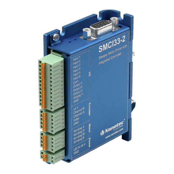
Overview Overview Introduction The stepper motor control SMCI33 is an extremely compact and cost-effective constant current power output stage with integrated Closed-Loop current control. Due to the great capacity and functions available, it offers designers and developers a rapid and simple method of resolving numerous drive requirements with less programming effort. -
Page 6: Connection And Commissioning
Connection diagram Introduction To operate a stepper motor with the SMCI33 stepper motor control, the wiring must be implemented according to the following connection diagram. Inputs (Pin 1 to 6) on the connector X1 and the encoder input (connector X2) can be used optionally. - Page 7 Technisches Handbuch SMCI33 Connection and commissioning Connection diagram SMCI33 Issue: V 2.2...
-
Page 8: Commissioning
This section describes the main first steps you need to take to be able to quickly begin working with the SMCI33 if you are using the NanoPro software from a PC. You will find more detailed information in the separate NanoPro manual. - Page 9 Select the <Communication> tab. In the field "Port", select the COM port to which The number of the COM the SMCI33 is connected. port to which the controller is connected can be found in the device manager of your Windows PC. (System control/system/hardware).
-
Page 10: Connections And Circuits
Technisches Handbuch SMCI33 Connections and circuits Connections and circuits Inputs and outputs (I/O): Connector X1 Introduction An overview of the assignments can be found in the wiring diagram in Section 2.1). This section looks in detail at the assignment, functions and circuits of the connector The connectors and sockets used are from Phoenix, order number: FK-MC 2/4/5/12. - Page 11 NanoPro. Input circuits All inputs (apart from the "Analogue In" input) are electrically isolated by optocouplers from the voltage supply of the SMCI33 and designed for 5 - 24 V input signals at an input current of 10 mA. Note: The voltage must not exceed 24 V.
-
Page 12: Encoder Connection: Connector X2
The following encoder resolutions can normally be processed by the controller: 192, 200, 256, 400, 500, 512, 1000, 1024, 2000, 2048. Recommended: Where possible, use Nanotec encoders with the order number WEDS/WEDL-5541 Xxx. If an encoder is not used, the "Disable" mode must be set in the "Error correction" tab in the "Rotation Direction Mode"... -
Page 13: Stepper Motor Connection: Connector X3
Connections and circuits Stepper motor connection: Connector X3 General information The motor is connected to the SMCI33 with a 4-wire cable. Twisted wire pair cables with braided shields are recommended. Danger of electrical surges Mixing up the connections can destroy the output stage! See also the data sheet of the connected stepper motor. -
Page 14: Voltage Supply Connection: Connector X4
Voltage supply connection: Connector X4 Permissible operating voltage The permissible operating voltage for the SMCI33 stepper motor control lies between +24 and +48 V DC; it must not exceed 50 V or fall below 21 V . A charging condenser with minimum 4700 µF (10000 µF) must be provided for the operating voltage to prevent exceeding the permissible operating voltage (e.g. -
Page 15: Rs485 Network: Connector X5
These network connections are set up via the RS485 interface. D-sub socket connector A 9 pin D-Sub socket connector is located on the top of the SMCI33 (connector X5). The connector X5 provides the optional connection to the RS485 network. - Page 16 Technisches Handbuch SMCI33 Connections and circuits Circuit diagram RS485 network Issue: V 2.2...
-
Page 17: Operating Modes
Technisches Handbuch SMCI33 Operating modes Operating modes Introduction Depending on the travel profile, the motor can be operated using different operation modes. Due to the great capacity and functions available, it offers designers and developers a rapid and simple method of resolving numerous drive requirements with less programming effort. - Page 18 Technisches Handbuch SMCI33 Operating modes Operation mode Application Clock direction mode, left Use this mode when you wish to operate the motor with a superordinate controller (e.g. CNC controller). Clock direction mode, right In the clock direction mode, the motor is operated via...
-
Page 19: Troubleshooting
Red LED on Overtemperature of power Switch off controller and allow to the SMCI33 electronics > 75 °C cool. lit up. The error is reset when the SMCI33 is disconnected from the power supply unit. Undervoltage Check voltage supply. Issue: V 2.2... -
Page 20: Technical Data
Adjustable up to max. 3 A/phase Continuous current 2 A/phase Current drop Adjustable 0 to 80% of phase current Interfaces • SMCI33-1: USB standard • SMCI33-2 RS-485 (4-wire) 115200 baud (adjustable) 1 start bit, 8 data bits, 1 stop bit... - Page 21 Technisches Handbuch SMCI33 Technical data SMCI33 dimensions A complete set of datasheets is available for downloading at www.nanotec.de. Connectors The following connectors are available on the SMCI33: • Connectors X1, X2, X3 and X4: Phoenix connector, type MICRO COMBICON • Connector X5: SMCI33-1: Mini-USB Type B –...
-
Page 22: Index
Protective circuits.......... 20 Connector X3..........13 Connector X4..........14 Rotation monitoring......... 6 Connector X5..........15 RS485 network ..........15 Encoder .............6, 12 SMCI33 functions..........5 Encoder connection diagram......12 Stepper motor ..........13 Input circuits ..........11 Two-wire operation ........15 Inputs and outputs (I/O).........10 Variants............5 NanoJ ..............6...