
Related Manuals for Tempco TPC40042


Summary of Contents for Tempco TPC40042
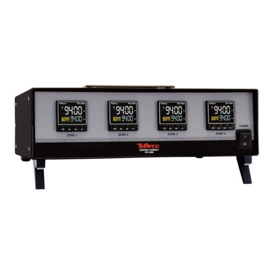
- Page 1 USER MANUAL TPC40042 - Power Control Console (4 zones) with TEC-9400 (PID + Fuzzy Logic Process Controller) Manual TPC40042 D1306.TE-401-402-404-405 Revision 2/22/2019 Revision 10/22 • D1400...
-
Page 3: Specifications
5. It is strongly recommended that a process should incorporate a Limit Control like a Tempco TEC-910 which will shut down the equipment at a preset process condition in order to avoid possible damage to products or systems. -
Page 4: Operation
2. Set your desired temperature setpoint by using the up and down arrow buttons on the TEC-9400 temperature controllers. 3. Refer to the following pages for complete operation and page 4 for auto-tuning of the TEC-9400 temperature controllers. SPARE/REPLACEMENT PARTS Tempco Description Part Number EHD-124-299 Fuses (2), rated 1 Amps/250V, 5 x 20mm, slow acting BUSS S505-1-R. - Page 5 TEC-9400 Front Panel Keys and Display KEYPAD OPERATION SCROLL KEY: This key is used to scroll through a menu to select a parameter to be viewed or adjusted. UP KEY: This key is used to increase the value of the selected parameter. DOWN KEY: This key is used to decrease the value of the selected parameter.
-
Page 6: Menu Flowchart
Menu Flowchart The Menu has been divided in to 5 groups. They are as follows: User Menu - Below Setup Menu - Page 5 Manual Mode Menu - Page 7 Auto-Tuning Mode Menu - Page 7 Calibration Mode Menu (not recommended, calibration section has been removed) Manual Mode Auto-Tuning Mode Calibration Mode Setup... - Page 7 1.1.2 Setup Menu The setup menu has been categorized in to eight categories. They are listed below. *5. User Select Menu 1. Basic Menu - Below *6. Communication Menu 2. Output Menu) - Page 6 *3. Alarm Menu *7. Current Transformer Menu *4.
- Page 8 1.1.2.2 Output Menu (oUT) In the setup menu, when the upper display says “SET”, use the key to get “oUT” in the lower display. Then, use the key to cycle through the “oUT” menu parameters (Note Chart on pg. 9) OUT1 - Pg.
- Page 9 1.1.3 Manual Mode Menu – (Use for Temporary Operation if Sensor Fails) (Also refer to pg. 18) Press and hold the “ ” key for approx. 6sec until the “HAND” parameter is shown in the upper display. Then, press and hold the “ ”...
-
Page 10: Parameter Description
1.2 Parameter Description (*Parameters that are not applicable are not shown) Parameter Default Register Parameter Description Range Notation Value Address Set Point 1 Low: SP1L 77.0° F High: SP1H (Used for Output 1) (25.0° C) 0 J_tC: J type Thermocouple 1 K_tC: K type Thermocouple 2 T_tC: T type Thermocouple 3 E_tC: E type Thermocouple... - Page 11 (*Parameters that are not applicable are not shown) Parameter Default Register Parameter Description Range Address Notation Value Basic 0 None: No Display Menu 1 MV1: Display MV1 2 MV2: Display MV2 DISP Secondary display selection 3 tIMR: Display Dwell Time 4 PRoF: display Profile Status Proportional band value 18.0°...
- Page 12 (*Parameters that are not applicable are not shown) Parameter Default Register Parameter Description Range Notation Value Address Basic Ramp rate Low: 0.0 Menu High: 900.0°F (See Pg. 13) Low: 0 PL1L Output 1 Low Power limit High:PL1H or 50% Output Menu Low: PL1L PL1H...
-
Page 13: User Security
Programming Press and hold for 5 seconds, then release to enter the setup menu. Press and release to cycle through the list of parameters. The upper display indicates the parameter symbol, and the lower display indicates the value of the selected parameter. User Security There are two parameters, PASS (password) and CODE (security code), which will control the lockout program. -
Page 14: Control Output
Control Output There are 4 kinds of control modes can be configured as shown below. 2.3.1 Heat Only ON-OFF Control – (Used for Solonoids and Valves) Select REVR for OUT1, Set PB to 0. O1HY is used to adjust the hysteresis for ON-OFF control. - Page 15 2.3.3 Heat only PID Control – (Default for Electric Heaters) Select REVR for OUT1. PB and TI should not be zero. Perform Auto-Tuning for initial startup. If the control result is not satisfactory, use manual tuning or try Auto-Tuning a second time to improve the control performance.
-
Page 16: Digital Filter
User Calibration - Display Offset Each unit is calibrated in the factory before shipment. The user can still modify the calibration in the field. The basic calibration of the controller is highly stable and set for life. User calibration allows the user to offset the permanent factory calibration in order to: ! Calibrate the controller to meet a user reference standard. -
Page 17: Failure Transfer
Note: The Filter is available only for the process value (PV), and is performed for the displayed value only. The controller is designed to use an unfiltered signal for control even when a filter is applied. If a lagged (filtered) signal is used for control; it may produce an unstable process. 2-4.Filter Characteristics Failure Transfer The controller will enter failure mode if one of the following conditions occurs:... - Page 18 2.8.1 Auto-Tuning Operation Steps 1. The system is set up to run under real-world conditions. 2. “PB and “TI” settings should not be set to zero. 3. The LOCK parameter should be set to NONE. 4. Set the set point to a normal operating value, or a lower value if overshooting beyond the normal process value will cause damage.
-
Page 19: Manual Tuning
Manual Tuning In certain applications, using Auto-Tuning may be inadequate for the control requirement, or, the process moves too slowly to Auto-tune accurately. If this is the case, the user can try manual tuning. If the control performance by using Auto-Tuning is still unsatisfactory, the following guidelines can be applied for further adjustment of PID values. -
Page 20: Manual Control
2.10 Manual Control To enable manual control, ensure the LOCK parameter is set to NONE. (Hand Control) appears on the display. Press and hold until Press and hold until the “MANU” indicator begins to flash. The lower display will show Indicates the output control variable for output 1, and indicates the control variable for output 2. -
Page 21: Error Code
6.4 Error Code The description of the Error code is explained below Error Code Display Symbol Description & Reason Corrective Action Check and correct setup values of OUT2, PB1, PB2, Illegal setup values used: COOL is TI1, TI2 and OUT1. IF OUT2 is needed for cooling used for OUT2 when DIRT (cooling control, the controller should use PID mode (PB≠... -
Page 22: Technical Support
800-323-6859 Note: Information in this manual was deemed correct at the time of printing. The policy of Tempco is one of continuous development and product improvement, and we reserve the right to modify specifications and designs without prior notice. Not responsible for typographical errors. - Page 24 Radiant Heaters Strip Heaters Flexible Heaters Tubular Heaters Process Heaters Instrumentation Temperature Control Temperature Sensors 607 N. Central Avenue Wood Dale, IL 60191-1452 USA P: 630-350-2252 Toll Free: 800-323-6859 F: 630-350-0232 E: info@tempco.com www.tempco.com © Copyright 2022 TEHC. All Rights Reserved...