Table of Contents
Advertisement
Advertisement
Table of Contents

Related Manuals for Asus ROG STRIX Z790-E GAMING WIFI


Summary of Contents for Asus ROG STRIX Z790-E GAMING WIFI
- Page 1 ROG STRIX Z790-E GAMING WIFI...
- Page 2 Product warranty or service will not be extended if: (1) the product is repaired, modified or altered, unless such repair, modification of alteration is authorized in writing by ASUS; or (2) the serial number of the product is defaced or missing.
-
Page 3: Table Of Contents
Contents Safety information ....................... v About this guide ......................vi ROG STRIX Z790-E GAMING WIFI specifications summary ......... vii Package contents ...................... xii Chapter 1: Product Introduction Before you proceed ................... 1-1 Motherboard layout ..................1-2 Chapter 2: Basic Installation Building your PC system ................ - Page 4 Appendix Q-Code table ......................A-1 Notices ........................A-5 Warranty ......................... A-16 ASUS contact information ..................A-18 Service and Support ..................... A-18...
-
Page 5: Safety Information
Safety information Electrical safety • To prevent electrical shock hazard, disconnect the power cable from the electrical outlet before relocating the system. • When adding or removing devices to or from the system, ensure that the power cables for the devices are unplugged before the signal cables are connected. If possible, disconnect all power cables from the existing system before you add a device. -
Page 6: About This Guide
Refer to the following sources for additional information and for product and software updates. ASUS website The ASUS website (www.asus.com) provides updated information on ASUS hardware and software products. Optional documentation Your product package may include optional documentation, such as warranty flyers, that may have been added by your dealer. -
Page 7: Rog Strix Z790-E Gaming Wifi Specifications Summary
ROG STRIX Z790-E GAMING WIFI specifications summary Intel Socket LGA1700 for 13 Gen Intel Core™ Processors & 12 ® ® Intel Core™, Pentium Gold and Celeron Processors* ® ® ® Supports Intel Turbo Boost Technology 2.0 and Intel Turbo Boost Max ®... - Page 8 ROG STRIX Z790-E GAMING WIFI specifications summary 1 x Intel 2.5Gb Ethernet ® Ethernet ASUS LANGuard Wi-Fi 6E 2x2 Wi-Fi 6E (802.11 a/b/g/n/ac/ax) Wireless & Bluetooth ® Supports 2.4/5/6GHz frequency band* Bluetooth v5.3 ® * WiFi 6E 6GHz regulatory may vary between countries.
- Page 9 ROG STRIX Z790-E GAMING WIFI specifications summary Fan and Cooling related 1 x 4-pin CPU Fan header 1 x 4-pin CPU OPT Fan header 1 x 4-pin AIO Pump header 5 x 4-pin Chassis Fan headers Power related 1 x 24-pin Main Power connector...
- Page 10 ROG STRIX Z790-E GAMING WIFI specifications summary ASUS EZ DIY - BIOS FlashBack™ button - BIOS FlashBack™ LED - Clear CMOS button - CPU Socket lever protector - ProCool II - Pre-mounted I/O shield - SafeSlot Special Features - SafeDIMM...
- Page 11 Form Factor 12 inch x 9.6 inch (30.5 cm x 24.4 cm) • Specifications are subject to change without notice. Please refer to the ASUS website for the latest specifications. • MyASUS offers a variety of support features such as helping to troubleshoot issues, optimizing product performance, integrating ASUS software, and recovery drive creation.
-
Page 12: Package Contents
Package contents Check your motherboard package for the following items. Motherboard 1 x ROG STRIX Z790-E GAMING WIFI motherboard Cables 2 x SATA 6Gb/s cables 1 x Thermal pad for M.2 Additional Cooling Kit 1 x DDR5 fan holder 1 x VRM fan holder... -
Page 13: Chapter 1: Product Introduction
• The pin definitions in this chapter are for reference only. The pin names depend on the location of the header/jumper/connector. • For more information on installing your motherboard, please scan the QR code below: ROG STRIX Z790-E GAMING WIFI... -
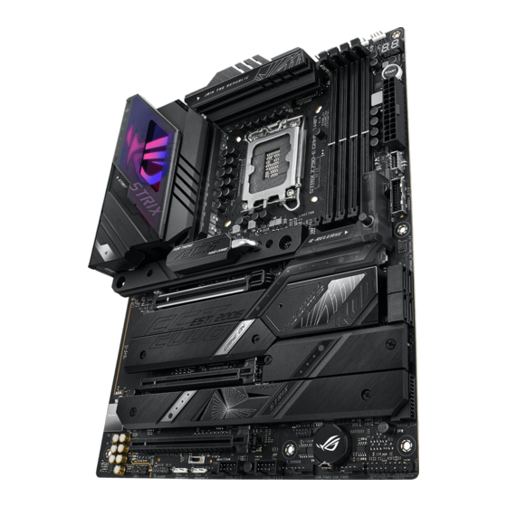
Page 14: Motherboard Layout
Motherboard layout Chapter 1: Product Introduction... - Page 15 16. Start button 1-18 17. System Panel header 1-19 18. Thermal Sensor header 1-20 19. Thunderbolt™ header 1-21 20. Q-Code LED 1-22 21. Q-LEDs 1-23 22. BIOS FlashBack™ LED 1-23 23. 8-pin Power Plug LED 1-24 ROG STRIX Z790-E GAMING WIFI...
- Page 16 Contact your retailer immediately if the PnP cap is missing, or if you see any damage to the PnP cap/socket contacts/motherboard components. ASUS will shoulder the cost of repair only if the damage is shipment/ transit-related.
- Page 17 (Double Data Rate 5) memory modules. A DDR5 memory module is notched differently from a DDR, DDR2, DDR3, or DDR4 module. DO NOT install a DDR, DDR2, DDR3, or DDR4 memory module to the DDR5 slot. Recommended memory configurations ROG STRIX Z790-E GAMING WIFI...
- Page 18 (D/C) from the same vendor. Check with the vendor to get the correct memory modules. • Visit the ASUS website for the latest QVL. Chapter 1: Product Introduction...
- Page 19 Expansion slots Unplug the power cord before adding or removing expansion cards. Failure to do so may cause you physical injury and damage motherboard components. ROG STRIX Z790-E GAMING WIFI...
- Page 20 Fan and Pump headers The Fan and Pump headers allow you to connect fans or pumps to cool the system. • DO NOT forget to connect the fan cables to the fan headers. Insufficient air flow inside the system may damage the motherboard components. These are not jumpers! Do not place jumper caps on the fan headers! •...
- Page 21 • If you want to use two or more high-end PCI Express x16 cards, use a PSU with 1000W power or above to ensure the system stability. ROG STRIX Z790-E GAMING WIFI...
- Page 22 M.2 slot The M.2 slot allows you to install M.2 devices such as M.2 SSD modules. • Intel & 12 Gen Processors: ® - M.2_1 supports PCIE 5.0 x4 mode M Key design and type 2242 / 2260 / 2280 / 22110 storage devices.
- Page 23 1, 5, and 10 configuration with the Intel Rapid Storage Technology through the onboard ® Intel Z790 chipset. ® Before creating a RAID set, refer to the RAID Configuration Guide. You can download the RAID Configuration Guide from the ASUS website. ROG STRIX Z790-E GAMING WIFI 1-11...
- Page 24 USB 3.2 Gen 2x2 Type-C Front Panel connector ® The USB 3.2 Gen 2x2 Type-C connector allows you to connect a USB 3.2 Gen 2x2 ® Type-C module for additional USB 3.2 Gen 2x2 ports on the front panel. The USB 3.2 ®...
- Page 25 2.0 ports. The USB 2.0 header provides data transfer speeds of up to 480 Mb/s connection speed. DO NOT connect a 1394 cable to the USB connectors. Doing so will damage the motherboard! The USB 2.0 module is purchased separately. ROG STRIX Z790-E GAMING WIFI 1-13...
- Page 26 Addressable Gen2 header The Addressable Gen2 header allows you to connect individually addressable RGB WS2812B LED strips or WS2812B based LED strips. The Addressable Gen2 header supports WS2812B addressable RGB LED strips (5V/ Data/Ground), with a maximum power rating of 3A (5V), and the addressable headers on this board can handle a combined maximum of 500 LEDs.
- Page 27 When the Alternative PCIe Mode switch is set to 2 step, the PCIe signal from the CPU will be Gen3, and LED2 will light up yellow. • The nearby LEDs indicate which PCIe mode is currently selected. ROG STRIX Z790-E GAMING WIFI 1-15...
- Page 28 Aura RGB header The Aura RGB header allows you to connect RGB LED strips. The Aura RGB header supports 5050 RGB multi-color LED strips (12V/G/R/B), with a maximum power rating of 3A (12V). Before you install or remove any component, ensure that the power supply is switched off or the power cord is detached from the power supply.
- Page 29 HD Audio. Connect one end of the front panel audio I/O module cable to this header. We recommend that you connect a high-definition front panel audio module to this connector to avail of the motherboard’s high-definition audio capability. ROG STRIX Z790-E GAMING WIFI 1-17...
- Page 30 Start button Press the Start button to power up the system, or put the system into sleep or soft-off mode (depending on the operating system settings). Chapter 1: Product Introduction 1-18...
- Page 31 The chassis intrusion sensor or switch sends a high-level signal to the header when a chassis component is removed or replaced, the signal is then generated as a chassis intrusion event. ROG STRIX Z790-E GAMING WIFI 1-19...
- Page 32 Thermal Sensor header The Thermal Sensor header allows you to connect a sensor to monitor the temperature of the devices and the critical components inside the motherboard. Connect the thermal sensor and place it on the device or the motherboard’s component to detect its temperature.
- Page 33 Please visit the official website of your purchased Thunderbolt™ card for more details on compatibility. The Thunderbolt™ card can only be used when installed to the PCIEX16(G4)_2 slot. Ensure to install your Thunderbolt™ card to the PCIEX16(G4)_2 slot. ROG STRIX Z790-E GAMING WIFI 1-21...
- Page 34 Q-Code LED The Q-Code LED design provides you with a 2-digit error code that displays the system status. • The Q-Code LEDs provide the most probable cause of an error code as a starting point for troubleshooting. The actual cause may vary from case to case. •...
- Page 35 BIOS FlashBack™ LED The BIOS FlashBack™ LED lights up or blinks to indicate the status of the BIOS FlashBack™. Refer to the BIOS update utility section for more information on using the BIOS FlashBack™ feature. ROG STRIX Z790-E GAMING WIFI 1-23...
- Page 36 8-pin Power Plug LED The 8-pin Power Plug LED lights up to indicate that the 8-pin power plug is not connected. Chapter 1: Product Introduction 1-24...
-
Page 37: Building Your Pc System
CPU designed for LGA1155, LGA1156, LGA1151, and LGA1200 sockets on the LGA1700 socket. • ASUS will not cover damages resulting from incorrect CPU installation/removal, incorrect CPU orientation/placement, or other damages resulting from negligence by the user. Take caution when lifting the load... - Page 38 Ensure to remove the CPU Socket lever protector on the lever latch before locking the lever latch under the retention tab. Failure to do so may cause damages to your system when installing the cooling system. Chapter 2: Basic Installation...
-
Page 39: Cooling System Installation
Ensure to remove the CPU Socket lever protector on the lever latch before installing the cooling system, failure to do so may cause damages to your system. To install a CPU heatsink and fan assembly ROG STRIX Z790-E GAMING WIFI... - Page 40 Intel ® 700 series motherboard. • Additional holes for LGA1200 compatible cooling systems are also available on ASUS’ Intel 700 series motherboards, ® however, we still strongly advise consulting with your cooling system vendor or manufacturer on the compatibility and...
- Page 41 • If you wish to install an AIO cooler, we recommend installing the AIO cooler after installing the motherboard into the chassis. AIO_PUMP CPU_FAN CPU_OPT ROG STRIX Z790-E GAMING WIFI...
-
Page 42: Dimm Installation
2.1.3 DIMM installation To remove a DIMM Chapter 2: Basic Installation... -
Page 43: M.2 Installation
Use a Phillips screwdriver when removing or installing the screws or screw stands mentioned in this section. • The M.2 is purchased separately. Completely loosen the screws on the heatsinks. Lift and remove the heatsinks. ROG STRIX Z790-E GAMING WIFI... - Page 44 Install your M.2 to your M.2 slot. The steps may differ between installing M.2 of different lengths, please refer to the different types and their installation steps below: • To install an M.2 to M.2_1 slot For 22110 length A. Remove the pre-installed M.2 Q-latch at the 2280 length screw hole by rotating the handle counterclockwise then pushing it towards the M.2 slot and removing it from the latch hole.
- Page 45 NOT install the bundled rubber for M.2 backplate when installing a double- sided M.2 storage device. Thermal pad Bundled rubber for M.2 backplate E. Install your M.2 to the M.2 slot. F. Rotate the M.2 Q-Latch clockwise to secure the M.2 in place. ROG STRIX Z790-E GAMING WIFI...
- Page 46 For 2280 length A. Rotate and adjust the M.2 Q-latch at the 2280 position so that the handle points away from the M.2 slot. B. Remove the plastic film from the thermal pad. C. (optional) Remove the thermal pad of the 2260 M.2 length screw hole and install the bundled rubber for M.2 backplate if you are installing a single sided M.2 storage device.
- Page 47 C. Remove the thermal pad of the M.2 length screw hole you wish to install your M.2 to, then install the M.2 Q-latch. D. Rotate and adjust the M.2 Q-latch so that the handle points away from the M.2 slot. Thermal pad M.2 Q-Latch ROG STRIX Z790-E GAMING WIFI 2-11...
- Page 48 E. (optional) Remove the thermal pad of the 2242 M.2 length screw hole and install the bundled rubber for M.2 backplate if you are installing a single sided M.2 storage device. DO NOT install the bundled rubber for M.2 backplate when installing a double-sided M.2 storage device. Follow this step only if you wish to install a single sided M.2 storage device to type 2260.
- Page 49 B. Rotate and adjust the M.2 Q-latch so that the handle points away from the M.2 slot. C. Install your M.2 to the M.2 slot. D. Rotate the M.2 Q-Latch clockwise to secure the M.2 in place. Bundled rubber for M.2 OPTIONAL ROG STRIX Z790-E GAMING WIFI 2-13...
- Page 50 For 2242, 2260 length A. (optional) Remove the M.2 rubber. Follow this step only if you wish to install an M.2 to type 2242. B. Install the M.2 Q-Latch to the M.2 length screw hole you wish to install your M.2 to.
- Page 51 If the thermal pad on the M.2 heatsink becomes damaged and needs to replaced, we recommend replacing it with a thermal pad with a thickness of 1.25mm. Replace the heatsinks. Secure the heatsinks using the screws removed previously. ROG STRIX Z790-E GAMING WIFI 2-15...
-
Page 52: Additional Cooling Kit Installation
2.1.5 Additional cooling kit installation To install the VRM fan holder • You may install a 12V (1A, 12W), 40mm x 40mm fan onto the fan holder if you require additional cooling for your motherboard. • The fan is purchased separately. To install the DDR5 fan holder •... -
Page 53: Motherboard Installation
I/O panel. Place nine (9) screws into the holes indicated by circles to secure the motherboard to the chassis. DO NOT over tighten the screws! Doing so can damage the motherboard. ROG STRIX Z790-E GAMING WIFI 2-17... -
Page 54: Atx Power Connection
2.1.7 ATX power connection Ensure to connect the 8-pin power plug or both 8-pin power plugs. Chapter 2: Basic Installation 2-18... -
Page 55: Sata Device Connection
2.1.8 SATA device connection ROG STRIX Z790-E GAMING WIFI 2-19... -
Page 56: Front I/O Connector
2.1.9 Front I/O connector To install the front panel connector To install USB 3.2 Gen 2x2 Type-C ® connector USB 3.2 Gen 2x2 Type-C ® This connector will only fit in one orientation. Push the connector until it clicks into place. To install USB 3.2 Gen 1 connector USB 3.2 Gen 1 USB 3.2 Gen 1... -
Page 57: Expansion Card Installation
2.1.10 Expansion card installation To install PCIe x16 cards ROG STRIX Z790-E GAMING WIFI 2-21... - Page 58 To install Thunderbolt™ series card 6-pin PCIe power connector USB Type-C ® port connects to Thunderbolt devices MiniDP in port connects to DP out port on the motherboard or a VGA card USB 2.0 header Thunderbolt™ header The Thunderbolt™ card can only be used when installed to the PCIEX16(G4)_2 slot. Ensure to install your Thunderbolt™...
- Page 59 This should release the expansion card so that you can remove it with ease. The illustration below is for reference only. The motherboard and PCIe Slot Q-Release button may differ between models, but the steps for using the PCIe Slot Q-Release remain the same. ROG STRIX Z790-E GAMING WIFI 2-23...
-
Page 60: Wi-Fi Moving Antenna Installation
2.1.11 Wi-Fi moving antenna installation Installing the ASUS Wi-Fi moving antenna Connect the bundled ASUS Wi-Fi moving antenna connector to the Wi-Fi ports at the back of the chassis. • Ensure that the ASUS Wi-Fi moving antenna is securely installed to the Wi-Fi ports. -
Page 61: Rear I/O Top Cover Installation
Rear I/O top cover installation This motherboard features a removable rear I/O top cover which you can remove or replace according to your needs. Removing the rear I/O top cover Replacing the rear I/O top cover ROG STRIX Z790-E GAMING WIFI 2-25... -
Page 62: Bios Update Utility
• Updating BIOS may have risks. If the BIOS program is damaged during the process and results to the system’s failure to boot up, please contact your local ASUS Service Center. Chapter 2: Basic Installation... - Page 63 For more information on using the BIOS FlashBack™ feature, please refer to https://www.asus.com/support/, or by scanning the QR code below. ROG STRIX Z790-E GAMING WIFI 2-27...
-
Page 64: Clear Cmos Button
Clear CMOS button The Clear CMOS button located on the rear I/O allows you to clear the Real Time Clock (RTC) RAM in the CMOS, which contains the date, time, system passwords, and system setup parameters. To erase the RTC RAM: Turn OFF the computer and unplug the power cord. -
Page 65: Motherboard Rear And Audio Connections
We strongly recommend that you connect your devices to ports with matching data transfer rate. For example connecting your USB 3.2 Gen 1 devices to USB 3.2 Gen 1 ports for faster and better performance for your devices. ROG STRIX Z790-E GAMING WIFI 2-29... -
Page 66: Audio I/O Connections
* Intel 2.5Gb Ethernet port LED indications ® Activity Link LED Speed LED ACT/LINK SPEED Status Description Status Description No link No link GREEN Linked 100 Mbps / 10 Mbps connection BLINKING Data activity LAN port GREEN 2.5 Gbps connection ORANGE 1 Gbps connection ** Audio 2, 4, 5.1 or 7.1-channel configuration... - Page 67 The rear panel Lime (Line out) port does not support spatial audio. If you wish to use spatial audio make sure to connect your audio output device to the audio jack on the front panel of your chassis. Connect to 2-channel Speakers Connect to 4-channel Speakers ROG STRIX Z790-E GAMING WIFI 2-31...
- Page 68 Connect to 5.1-channel Speakers Connect to 7.1-channel Speakers Chapter 2: Basic Installation 2-32...
-
Page 69: Starting Up For The First Time
While the system is ON, press the power button for less than four seconds to put the system on sleep mode or soft-off mode, depending on the BIOS setting. Press the power button for more than four seconds to let the system enter the soft-off mode regardless of the BIOS setting. ROG STRIX Z790-E GAMING WIFI 2-33... - Page 70 Chapter 2: Basic Installation 2-34...
-
Page 71: Chapter 3: Bios And Raid Support
Knowing BIOS The new ASUS UEFI BIOS is a Unified Extensible Interface that complies with UEFI architecture, offering a user-friendly interface that goes beyond the traditional keyboard- only BIOS controls to enable a more flexible and convenient mouse input. You can easily navigate the new UEFI BIOS with the same smoothness as your operating system. -
Page 72: Bios Setup Program
BIOS setup program Use the BIOS Setup to update the BIOS or configure its parameters. The BIOS screen include navigation keys and brief onscreen help to guide you in using the BIOS Setup program. Entering BIOS at startup To enter BIOS Setup at startup, press <Delete> or <F2> during the Power-On Self Test (POST). -
Page 73: Asus Ez Flash 3
ASUS EZ Flash 3 The ASUS EZ Flash 3 feature allows you to update the BIOS without using an OS-based utility. Ensure to load the BIOS default settings to ensure system compatibility and stability. Select the Load Optimized Defaults item under the Exit menu or press hotkey <F5>. -
Page 74: Asus Crashfree Bios 3
ASUS CrashFree BIOS 3 The ASUS CrashFree BIOS 3 utility is an auto recovery tool that allows you to restore the BIOS file when it fails or gets corrupted during the updating process. You can restore a corrupted BIOS file using a USB flash drive that contains the BIOS file. -
Page 75: Raid Configurations
For more information on configuring your RAID sets, please refer to the RAID Configuration Guide which you can find at https://www.asus.com/support, or by scanning the QR code. RAID definitions RAID 0 (Data striping) optimizes two identical hard disk drives to read and write data in parallel, interleaved stacks. - Page 76 Chapter 3: BIOS Setup...
-
Page 77: Appendix
CPU self test failed or possible CPU cache error CPU micro-code is not found or micro-code update is failed Internal CPU error Reset PPI is not available Reserved for future AMI error codes 5C – 5F (continued on the next page) ROG STRIX Z790-E GAMING WIFI... -
Page 78: Q-Code Table
Q-Code table Code Description S3 Resume is stared (S3 Resume PPI is called by the DXE IPL) S3 Boot Script execution Video repost OS S3 wake vector call E4 – E7 Reserved for future AMI progress codes S3 Resume Failed S3 Resume PPI not Found S3 Resume Boot Script Error S3 OS Wake Error... - Page 79 Reserved for ASL (see ASL Status Codes section below) Ready To Boot event Legacy Boot event Exit Boot Services event Runtime Set Virtual Address MAP Begin Runtime Set Virtual Address MAP End Legacy Option ROM Initialization System Reset (continued on the next page) ROG STRIX Z790-E GAMING WIFI...
- Page 80 Q-Code table Code Description USB hot plug PCI bus hot plug Clean-up of NVRAM Configuration Reset (reset of NVRAM settings) Reserved for future AMI codes B8– BF CPU initialization error System Agent initialization error PCH initialization error Some of the Architectural Protocols are not available PCI resource allocation error.
-
Page 81: Notices
RF exposure compliance. HDMI Trademark Notice The terms HDMI, HDMI High-Definition Multimedia Interface, HDMI Trade dress, and the HDMI Logo are trademarks or registered trademarks of HDMI Licensing Administrator, Inc. ROG STRIX Z790-E GAMING WIFI... - Page 82 Compliance Statement of Innovation, Science and Economic Development Canada (ISED) This device complies with Innovation, Science and Economic Development Canada licence exempt RSS standard(s). Operation is subject to the following two conditions: (1) this device may not cause interference, and (2) this device must accept any interference, including interference that may cause undesired operation of the device.
- Page 83 Tenez cet appareil à distance du ventre des femmes enceintes et du bas-ventre des adolescents. ROG STRIX Z790-E GAMING WIFI...
- Page 84 ASUS products sold in Vietnam, on or after September 23, 2011,meet the requirements of the Vietnam Circular 30/2011/TT-BCT. Các sản phẩm ASUS bán tại Việt Nam, vào ngày 23 tháng 9 năm2011 trở về sau, đều phải đáp ứng các yêu cầu của Thông tư 30/2011/TT-BCT của Việt Nam.
- Page 85 Accessories that came with this product have been designed and verified for the use in connection with this product. Never use accessories for other products to prevent the risk of electric shock or fire. 安全上のご注意 付属品は当該専用品です。 他の機器には使用しないでください。 機器の破損もしくは、 火災や感 電の原因となることがあります。 ROG STRIX Z790-E GAMING WIFI...
- Page 86 ASUSTek Computer Inc. hereby declares that this device is in compliance with the essential requirements and other relevant provisions of The Radio Equipment Regulations 2017 (S.I. 2017/1206). Full text of UKCA declaration of conformity is available at https://www.asus.com/support/. The WiFi operating in the band 5150-5350MHz shall be restricted to indoor use for the country listed below:...
- Page 87 إعالن التوافق المبسط الصادر عن االتحاد األوروبي 2014/53/EU. La déclaration de conformité de l’UE peut être téléchargée à partir du site internet suivant : https://www.asus.com/support/. أن هذا الجهاز يتوافق مع المتطلبات األساسية واألحكامASUSTek Computer تقر شركة /35/4102. يتوفر النص الكامل إلعالن التوافقEU األخرى ذات الصلة الخاصة بتوجيه...
- Page 88 Käesolevaga kinnitab ASUSTek Computer Inc, et seade vastab direktiivi zahtjevima i ostalim odgovarajućim odredbama direktive 2014/53/EU. Cijeli 2014/53/EÜ olulistele nõuetele ja teistele asjakohastele sätetele. EL tekst EU izjave o sukladnosti dostupan je na https://www.asus.com/support/. vastavusdeklaratsiooni täistekst on saadaval veebisaidil https://www.asus.com/support/.
- Page 89 (IE), Lietuvā (LT), Vācijā (DE), Nīderlandē (NL), Spānijā (ES). 5945 a 6425 MHz na Bélgica (BE), Bulgária (BG), Chipre (CY), República Checa (CZ), Estónia (EE), França (FR), Islândia (IS), Irlanda (IE), Lituânia (LT), Alemanha (DE), Países Baixos (NL), Espanha (ES). ROG STRIX Z790-E GAMING WIFI A-13...
- Page 90 Direktive 2014/53/EU. Polno 5150-5350 MHz arasındaki WiFi çalışması, tabloda listelenen ülkeler için besedilo izjave EU o skladnosti je na voljo na https://www.asus.com/ iç mekân kullanımıyla kısıtlanacaktır. support/. Düşük Güç İç Mekan (LPI) Wi-Fi 6E cihazları: WiFi, ki deluje v pasovnem območju 5150–5350 MHz, mora biti v državah,...
- Page 91 5150 - 5350 MHz 20 dBm WiFi 5470 - 5725 MHz 19 dBm 5725 - 5850 MHz 11 dBm 5945 - 6425 MHz 21 dBm Bluetooth 2402 - 2480 MHz 13 dBm * Receiver category 1 ROG STRIX Z790-E GAMING WIFI A-15...
-
Page 92: Warranty
• ASUS offers a voluntary manufacturer’s Commercial Guarantee. • ASUS dragovoljno nudi komercijalno proizvođačko jamstvo. • ASUS reserves the right to interpret the provisions of the ASUS • ASUS zadržava prava na tumačenje odredbi ASUS komercijalnog Commercial Guarantee. jamstva. •... - Page 93 • ASUS tilbyr som produsent en frivillig kommersiell garanti. • Bảo hành thương mại này của ASUS được cung cấp độc lập và ngoài • ASUS forbeholder seg retten til å tolke bestemmelsene i ASUS sin Bảo đảm pháp lý theo luật định và không có cách nào ảnh hưởng đến kommersielle garanti.
-
Page 94: Asus Contact Information
Address: 1F., No. 15, Lide Rd., Beitou Dist., Taipei City 112 ASUS COMPUTER INTERNATIONAL (America) Address: 48720 Kato Rd., Fremont, CA 94538, USA ASUS COMPUTER GmbH (Germany and Austria) Address: Harkortstrasse 21-23, 40880 Ratingen, Germany ASUSTeK (UK) LIMITED Address: 1st Floor, Sackville House, 143-149 Fenchurch Street, London, EC3M 6BL,...