Table of Contents
Troubleshooting

Related Manuals for PowCon PD62

Summary of Contents for PowCon PD62
- Page 1 OM-180 059 February 1997 Eff. w/Serial Number KG220625 Processes MIG (GMAW) Welding Flux Cored (FCAW) Welding (Gas- and Self-Shielding) Submerged (SAW) Welding Description Wire Feeder (Use with CV Power Sources) PD62 & PD64...
- Page 3 Declaration of Conformity for European Community (CE) Products NOTE This information is provided for units with CE certification (see rating label on unit). PowCon Incorporated Manufacturer’s Name: 8123 Miralani Drive Manufacturer’s Address: San Diego, CA 92126 USA PD60 Declares that the product:...
-
Page 5: Section 1 − Safety Precautions - Read Before Using
SECTION 1 − SAFETY PRECAUTIONS - READ BEFORE USING som _nd_5/97 1-1. Symbol Usage Means Warning! Watch Out! There are possible hazards with this procedure! The possible hazards are shown in the adjoining symbols. This group of symbols means Warning! Watch Out! possible Y Marks a special safety message. - Page 6 ARC RAYS can burn eyes and skin. BUILDUP OF GAS can injure or kill. D Shut off shielding gas supply when not in use. Arc rays from the welding process produce intense visible and invisible (ultraviolet and infrared) rays D Always ventilate confined spaces or use that can burn eyes and skin.
-
Page 7: Principal Safety Standards
1-3. Additional Symbols For Installation, Operation, And Maintenance FIRE OR EXPLOSION hazard. MOVING PARTS can cause injury. D Do not install or place unit on, over, or near D Keep away from moving parts such as fans. combustible surfaces. D Keep all doors, panels, covers, and guards D Do not install unit near flammables. -
Page 8: Emf Information
1-5. EMF Information Considerations About Welding And The Effects Of Low Frequency 1. Keep cables close together by twisting or taping them. Electric And Magnetic Fields 2. Arrange cables to one side and away from the operator. Welding current, as it flows through welding cables, will cause electro- magnetic fields. -
Page 9: Section 1 − Consignes De Securite − Lire Avant Utilisation
SECTION 1 − CONSIGNES DE SECURITE − LIRE AVANT UTILISATION som _nd_fre 5/97 1-1. Signification des symboles Signifie Mise en garde ! Soyez vigilant ! Cette procédure présente des risques de danger ! Ceux-ci sont identifiés par des symboles adjacents aux directives. Ce groupe de symboles signifie Mise en garde ! Soyez vigilant ! Il y a des Y Identifie un message de sécurité... - Page 10 LES RAYONS DE L’ARC peuvent pro- LES ACCUMULATIONS DE GAZ ris- voquer des brûlures dans les yeux et quent de provoquer des blessures ou sur la peau. même la mort. Le rayonnement de l’arc du procédé de soudage D Fermer l’alimentation du gaz protecteur en cas de génère des rayons visibles et invisibles intenses non utilisation.
-
Page 11: Dangers Supplémentaires En Relation Avec L'installation, Le Fonctionnement Et La Maintenance
1-3. Dangers supplémentaires en relation avec l’installation, le fonctionnement et la maintenance Risque D’INCENDIE OU DES ORGANES MOBILES peuvent D’EXPLOSION. provoquer des blessures. D Ne pas placer l’appareil sur, au-dessus ou à proxi- D Rester à l’écart des organes mobiles comme le mité... -
Page 12: Principales Normes De Sécurité
1-4. Principales normes de sécurité Safety in Welding and Cutting, norme ANSI Z49.1, de l’American Wel- Safe Handling of Compressed Gases in Cylinders, CGA Pamphlet P-1, ding Society, 550 N.W. Lejeune Rd, Miami FL 33126 de la Compressed Gas Association, 1235 Jefferson Davis Highway, Suite 501, Arlington, VA 22202. -
Page 13: Section 2 − Definitions
SECTION 2 − DEFINITIONS 2-1. Warning Label Definitions Warning! Watch Out! There are possible hazards as shown by the symbols. Drive rolls can injure fingers Welding wire and drive parts are at welding voltage during operation − keep hands and metal objects away. -
Page 14: Rating Label For Ce Products
2-2. Rating Label For CE Products S/N: 50/60 IP 23 10.0 X 100 % Ref. S-178 794-A 2-3. Symbols And Definitions NOTE Some symbols are found only on CE products. Amperes Volts Alternating Current Duty Cycle Degree Of Hertz Circuit Breaker Wire Feed Protection Output... -
Page 15: Section 3 − Installation
SECTION 3 − INSTALLATION 3-1. Specifications Wire Welding Type of Input Welding Power Wire Feed Overall Diameter Circuit Weight Power Source Type Speed Range Rating Dimensions Range Rating Standard: 50 To Length: 26-1/2 in 100 Volts, .023 To 1/8 in 780 ipm (1.3 To (673 mm) 24 Volts AC... -
Page 16: Site Selection
3-2. Site Selection Wire Feeder Lifting Eye Rubber Feet Slot Choose slot that allows all rubber feet to sit securely on top of welding power source. Wire Spool/Reel Gas Cylinder (Customer Supplied) Welding Power Source Y Do not put feeder where welding wire hits cylinder. -
Page 17: Equipment Connection Diagrams
3-4. Equipment Connection Diagrams Welding Power Source Contactor Control/Power Cord Positive (+) Weld Cable Negative (−) Weld Cable Workpiece Voltage Sensing Lead (Optional) Wire Feeder ATC-24 Control (Optional) Use with welding power sources supplying 115 volts ac power. 10 Gas Hose 11 Gas Cylinder ST-152 319 / ST-152 320 OM-180 059 Page 13... -
Page 18: Rear Panel Connections And Rotating Drive Assembly
3-5. Rear Panel Connections And Rotating Drive Assembly Customer Supplied Gas Hose Shielding Gas Valve Fitting Requires fitting with 5/8-18 right- hand threads. Optional Reed Relay Tools Needed: Connection 9/16, 5/8, 11/16 in Power Switch 3/16 in Voltage Sensing Lead 14-Pin Cord Weld Cable Weld Cable Terminal... -
Page 19: Pin Plug Information
3-6. 14-Pin Plug Information Pin* Pin Information 24 volts ac with respect to socket G. Contact closure to A completes 24 volts ac contactor control circuit. Circuit common. +10 volts dc output to remote control with respect to socket D. Remote control circuit common. -
Page 20: Installing And Threading Welding Wire
3-8. Installing And Threading Welding Wire If necessary, move hub and spool support so wire runs straight from Tools Needed: the spool through the drive rolls. Install wire spool. Adjust tension nut so wire is taut when wire feed stops. 3/16, 5/64 in Install wire guides and anti-wear guide. -
Page 21: Optional Equipment Dip Switch Settings
3-9. Optional Equipment DIP Switch Settings X Means switch can be in either position. . Means switch must be in this position. Option Interface Standard Settings Spot Time Range Selection Long Spot Time 0-5 Seconds Short Spot Time 0-2.5 Seconds Digital Meter Functions Standard Standard... - Page 22 3-10. Changing Optional Digital Voltage Control For Use With A PowCon Inverter-Type Power Source Digital Voltage Control Board Connections For Standard Digital Voltage Control Board Connections For Use With PowCon Inverter-Type Weld- ing Power Source Change plug connections shown. Calibration Potentiometer R31...
-
Page 23: Section 4 − Operation
Press To Set Button (Optional) When a digital voltage control is used with a To start weld, press and release gun trigger Press and hold button to preset Schedule B PowCon inverter-type welding power within three seconds after an arc has been wire feed speed and/or voltage. -
Page 24: Overload Protection And Optional Side Panel Controls
4-2. Volts Meter Display Voltage Control Type Volts Meter Weld Not Weld Display Hold See Note Weld value for 15 seconds, then 0 or OCV Standard 1-Turn Control Monitor Actual 0 or OCV Digital 10-Turn Control Hold See Note Weld value for 15 seconds, then preset Monitor Actual Preset... -
Page 25: Section 5 − Maintenance & Troubleshooting
SECTION 5 − MAINTENANCE & TROUBLESHOOTING 5-1. Routine Maintenance Y Disconnect power before maintaining. 3 Months Clean Repair Or Replace Replace Tighten Unreadable Cracked Weld Labels Weld Terminals Cable Replace 14-Pin Cord Cracked Hose And Cable Parts Fittings 6 Months Blow Out Or Clean Vacuum Inside. -
Page 26: Troubleshooting
5-2. Troubleshooting Y Disconnect power before troubleshooting Trouble Remedy Wire feeds, shielding gas flows, but elec- Check interconnecting cord connections. If secure, check cord for continuity and repair or replace (see trode wire is not energized. Sections 3-4 and 3-5). Wire feeder is on, meter(s) do not light Check and reset CB1 (see Section 4-3). -
Page 27: Section 6 − Electrical Diagrams
SECTION 6 − ELECTRICAL DIAGRAMS SB-164 371 Figure 6-1. Circuit Diagram For Wire Feeder OM-180 059 Page 23... - Page 28 Figure 6-2. Circuit Diagram For Wire Feeder With Optional Equipment OM-180 059 Page 24...
- Page 29 SD-173 659 OM-180 059 Page 25...
-
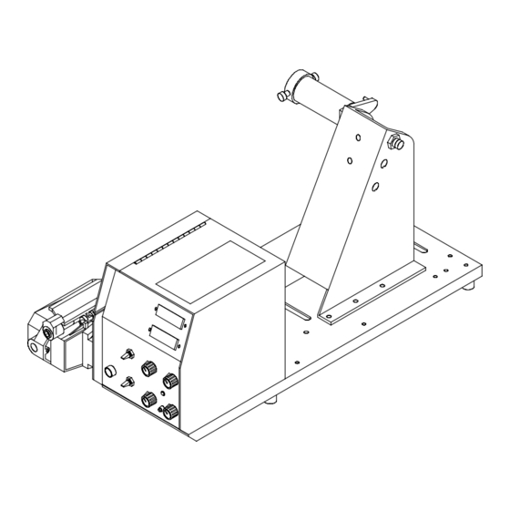
Page 30: Section 7 − Parts List
SECTION 7 − PARTS LIST Fig 7-3 Fig 7-2 ST-136 987-G Figure 7-1. Main Assembly OM-180 059 Page 26... - Page 31 Item Part Description Quantity Figure 7-1. Main Assembly ....141 753 HUB & SPINDLE ASSEMBLY, (consisting of) ..... . .
- Page 32 Fig 7-4 *See option that is applicable ST-142 438-E Figure 7-2. Control Box OM-180 059 Page 28...
- Page 33 Item Dia. Part Description Quantity Mkgs. Figure 7-2. Control Box (Fig 7-1 Item 16) ... . . 048 282 CONNECTOR w/SOCKETS, (consisting of) ..... . .
- Page 34 Item Dia. Part Description Quantity Mkgs. Figure 7-2. Control Box (Fig 7-1 Item 16) (Continued) ..PLG7 ..115 092 CONNECTOR & SOCKETS, (consisting of) ..... . .
- Page 35 Item Dia. Part Description Quantity Mkgs. Figure 7-3. Drive Assembly, Wire (Fig 7-1 Item 25) Drive Drive Roll Roll ....010 668 SCREW, cap stl sch .250-20 x 1.500 .
- Page 36 Item Dia. Part Description Quantity Mkgs. Figure 7-3. Drive Assembly, Wire (Fig 7-1 Item 25) Drive Drive (Continued) Roll Roll ....010 837 PIN, spring CS .093 x .625 .
- Page 37 Item Dia. Part Description Quantity Mkgs. Figure 7-4. Control Panel (Fig 7-2 Item 7) ♦121 893 ... . . SWITCH, tgl SPDT 6A 125VAC ....... . .
- Page 38 OM-180 059 Page 34...
- Page 39 This claim is valid for 60 days thereafter. of the time and place of delivery by PowCon. The This warranty is valid for all equipment manufactured limited warranty is for the periods indicated below, by PowCon after March 25, 1996.
-
Page 40: Owner's Record
Owner’s Record Please complete and retain with your personal records. Model Name Serial/Style Number Purchase Date (Date which equipment was delivered to original customer.) Distributor Address City State Resources Available Always provide Model Name and Serial/Style Number. Welding Supplies and Consumables Contact your Distributor for: Options and Accessories Personal Safety Equipment...