
Related Manuals for NDT James Instruments Cementometer L


Summary of Contents for NDT James Instruments Cementometer L
- Page 1 T-C-20 Cementometer™ L Operating Instructions Original Instructions: Revision: May 2019...
-
Page 2: Table Of Contents
Table of Contents T-C-20 General Overview ............. 3 Fine Aggregate ............. 5 Coarse Aggregate ............7 Mixing your Sample ............. 8 Menu Items ............... 11 Unit Operation ............. 11 Type I ................11 Type III ................ 11 Direct… ..............12 User Program ............. -
Page 3: T-C-20 General Overview
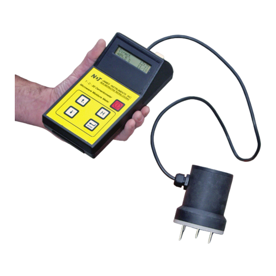
T-C-20 Cementometer™ L Instruction Manual GENERAL OVERVIEW James® Instruments Cementometer™- L is a revolutionary digital meter for low Water/Cement (or w/c) ration concrete. It allows the user to measure the complex dielectric constant of the mixture of water and material under investigation. As it has been shown in many studies that the complex dielectric constant is directly related to the amount of water present, the built-in microprocessor can convert this value directly into the percentage of moisture. - Page 4 used for the most accurate readings. There are also the capabilities to upload the data stored in the unit to a P.C. for later analysis, as well as a clock to help synchronize and differentiate the data. Finally, the unit comes with our P.C. software which simplifies uploading of data to a Windows Compatible P.C.
-
Page 5: Fine Aggregate
Calibration Procedure Preparation of Concrete Sample Fine Aggregate (Sand) We advise using ASTM C-128 & ASTM C-127 when preparing a cement mix for calibration of a user mode for the Cementometer™ unit. A Saturated-Surface Dry (or SSD) condition is very important. ASTM-C-128-15: Standard Test Method for Relative Density (Specific Gravity) and Absorption of Fine Aggregate. - Page 6 Step 5 For proper SSD determination a commercially bought cone should be used, ASTM C 128-15, 6.4 specs the mold as follows. “6.4 Mold and Tamper for surface Moisture Test - The metal mold shall be in the form of a frustum of a cone with dimensions as follows: 40 ±...
-
Page 7: Coarse Aggregate
Coarse Aggregate The following procedure is used to determine the SSD of Coarse Aggregate using ASTM C-127 standard. It is advised to use this standard when preparing a cement mix for the calibration of a user mode of the Cementometer™ L unit. Step 1 Place the course aggregate sample in an oven safe tray and dry the sample for 24 hr ±... -
Page 8: Mixing Your Sample
Having your aggregates at SSD when mixing is very important and the following equation should be used to determine the percentage of moisture required to SSD your aggregate. Absorption, % = [(B - A) / A] x 100 A = mass of oven dry test sample in air, g. B = mass of surface-saturated-dry test sample in air, g. - Page 9 Step 4 Add 50 % of the fine aggregate and cement into the drum. Step 5 Add 60 % of the coarse aggregate and the remaining water until approximately 1/4 to 1/3 of the water is remaining in the reservoir being used to contain water. Step 6 Add the remaining fine aggregate and cement to the drum followed by the remaining coarse aggregate and water.
- Page 10 Step 9 For the mixture design presented in the example, add 1.45 lbs of water to the mix, or the corresponding amount of water to increase the w/c of your mix to 0.25 and let the drum rotate for 1 minute. This is now 0.25 w/c ratio concrete mix, and it is ready for testing with the Cementometer™.
-
Page 11: Menu Items
Menu Items UNIT OPERATION The Cementometer™ L was designed for simple operation. Upon start up, the unit should show a brief (five second) display of our company name and the software version. The unit will then proceed directly to the menu item it was last on before it was turned off. -
Page 12: Direct
DIRECT This mode is used when calibrating the unit directly to a user material. This shows the raw mV reading coming to the A-D converter of the unit from the sensor. By recording the value for a range of moistures and correlating this value, the unit will then be calibrated for the specific material being monitored by the Cementometer™... -
Page 13: Upload Data
For further information regarding the meaning of the OFFSET and GAIN parameters, please refer to the “General Notes on the User Program.” UPLOAD DATA Please follow the bottom steps in order to upload the data stored in the unit to a P.C. •... - Page 14 • Pressing the plus or minus keys will increment the digits at the cursor. Holding the plus or minus key will increment the value rapidly. • Pressing the enter Key will store the value selected and move the cursor to the next proper position. •...
-
Page 15: Pc Software Functions
P.C. SOFTWARE Functions • Open (Ctrl + O) Opens previously saved files containing data. • Close Closes currently open files • Save • Saves As Saves uploaded data. Files are saved as *.TXT file for later analysis via spreadsheet, or insertion into a word processor program. •... - Page 16 • Analyze (Ctrl + A) Allows the user to view individual records, graph data, and determine the correct coefficients for the user program. This key should only be used when data is uploaded from the unit that was saved in direct mode. It is then used to analyze the data and generate a user program.
-
Page 17: Least Squares Analysis
LEAST SQUARES ANALYSIS OF A STRAIGHT-LINE FIT For this method, we assume that there exists a linear relationship between the output of the probe, and the amount of moisture in the material to be tested. This relationship takes the following form: w/c ratio = Gain * Direct Reading + Offset (or y = a * x + b) (aka. -
Page 18: Warranty Information
Warranty Information 1. Contract Unless otherwise stated all sales transactions are expressly subject to these terms and conditions. Modification or additions will be recognized only if accepted in writing by an authorized Officer of James® Instruments Inc. (hereinafter referred to as “James®” or the “Company”), or an officially designated representative. - Page 19 to usual wear and tear during usage. Refer to the Consumable, Wear and Tear Items section of this warranty document. Option for Extended Limited Warranty Coverage The original purchaser of any new equipment of James® which have been identified or labeled by James® from time to time in James®'s sole discretion as being eligible for extended warranty coverage shall have the option to purchase certain extensions of the applicable limited...
- Page 20 James® supplies consumable items and items subject to wear and tear during normal usage of James® supplied products. These items are not covered under warranty. Buyer is to check for proper fit, form and function of such items upon receipt of such items. In case of a defect condition, Buyer can return the item to James®...
- Page 21 c. Warranty Claims i. For Warranty Claim Processing James® has established James® organizations in the Americas, and Europe. Please visit the James® web site www.ndtJames®.com for latest address and contact information for the James® organization nearest you. 3. Regulatory Laws and/or Standards The performance of the parties hereto is subject to the applicable laws of the United States.
- Page 22 any other relief. The Hague Convention and the United Nations Convention on Contracts for the International Sale of Goods shall not apply to the construction or interpretation of these Standard Terms and Conditions or affect any of its provisions. END.
-
Page 23: Repair Policy
Repair Policy United States | Canada | International Ship the instrument in a box that meets UPS, Fed Ex, and standard shipping regulations. Enclose a note describing the problem(s) you are having. Include the name and phone number of the contact person in your organization. - Page 24 James® Instruments Inc. 3727 N.Kedzie Ave. Chicago, IL 60618-4503 Tel: (773) 463-6565 Fax: (773) 463-0009 James® Instruments Inc. - Europe Windmolen 22 7609 NN Almelo The Netherlands Tel: +31 (0)548 659032 Fax: +31 (0)548 659010 Purchase Date: ____________________ Serial Number: ____________________...