Cobra 19 DX IV - Mobile Radio Manual
- Owner's manual (11 pages) ,
- Owner's manual (11 pages) ,
- Owner's manual (11 pages)
Advertisement
- 1 Product Features
- 2 Warnings
- 3 Included in this Package
- 4 Mounting and Connections
-
5
Operation
- 5.1 Antenna Connector
- 5.2 External Speaker
- 5.3 Public Address (PA)
- 5.4 Power
- 5.5 Turning on Your Mobile Radio
- 5.6 CB Antenna
- 5.7 Microphone Connector
- 5.8 Squelch
- 5.9 RF Gain
- 5.10 Selecting a Channel
- 5.11 Channel 9/NOR/Channel 19
- 5.12 CB/PA
- 5.13 S/RF Power Meter
- 5.14 TX Indicator
- 5.15 Ignition Noise Interference
- 5.16 Temporary Mobile Operation
- 5.17 Operating Procedure to Receive
- 5.18 Operating Procedure to Transmit
- 6 Maintenance/Adjustment
- 7 Frequency Ranges
- 8 Specifications
- 9 Documents / Resources
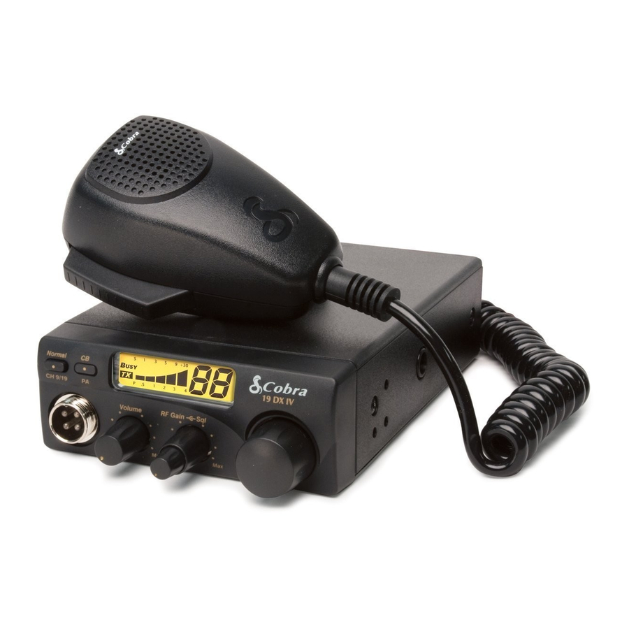
Product Features


Features
- 40 CB Radio Channels
- Instant Channels 9/19 NOR
- PA System
- Compact Size
- Dynamic Microphone
- Nine Foot Microphone Cord
- Front Panel Microphone Connector
- RF Gain
Warnings
 REPLACEMENT WARNING
Replacement or substitution of certain parts with replacements other than those recommended by Cobra may be a violation of the technical regulations of Part 95 of the FCC rules, or of Type Acceptance requirements of Part 2 of those rules.
When making adjustments, be sure to re-read applicable portions of this instruction manual to make certain you are following correct procedure and that the radio was properly installed.
A FEW RULES THAT SHOULD BE OBEYED
- You are not allowed to carry on a conversation with another station for more than five minutes at a time without taking a one-minute break to give others a chance to use the channel.
- You are not allowed to blast others off the air by overpowering them with illegally amplified transmitter power or illegally high antennas.
- You are not allowed to use CB to promote illegal activities.
- You are not allowed to use profanity.
- You may not play music in your CB.
- You may not use your CB to sell merchandise or professional service.
CHANNEL 9 EMERGENCY MESSAGES
Use Channel 9 for emergency messages only. The FCC gives the following examples of permitted and prohibited types of communications for use on Channel 9. These are guidelines and are not intended to be all-inclusive.
Permitted: "A tornado sighted six miles of town."
Not Permitted: "This is observation post number 10. No tornado sighted."
Included in this Package
You should find all of the following items in this package:

Mounting and Connections
Select a location for the transceiver and microphone bracket that is convenient for operation. In automobiles, the transceiver is usually mounted to the underneath of the dash panel, with the microphone bracket beside it.
A universal mounting bracket is supplied along with self tapping screws and star washers. The transceiver is held in the universal mounting bracket by two thumb screws, permitting adjustment at the most convenient angle.
To mount and connect your transceiver:
- Hold the radio with mounting bracket in the exact location desired. Remove the mounting bracket and use it as a template to mark the location for the mounting screws.
![]()
- Drill necessary holes and secure mounting bracket in location.
- Connect the antenna cable plug to the receptacle marked "ANT" on the back of the unit.
![]()
- Connect the red lead of the DC power cord to an accessory 12 volt fuse.
![]()
- Connect the black lead to the negative side of the automobile. This is usually the chassis. Any convenient location with good electrical contact (remove paint) may be used.


 NOTE
NOTE
Before installing the CB radio, visually check the vehicle battery connections to determine which battery terminal, positive or negative (positive is the larger of the two) is grounded to the engine block (or chassis).
- Mount the microphone bracket on right side of the transceiver or near it using two screws supplied. When mounting in an automobile, place the bracket under the dash so the microphone is readily accessible.
- Attach the four pin microphone cable to receptacle on front of unit and install unit in bracket securely.
![]()

Operation
Antenna Connector
This female Connector on the rear panel permits connection of the transmission line cable male connector to the transceiver.

External Speaker
The external speaker jack on the rear panel is used for an External Speaker. The external speaker should have 8-ohm impedance and be rated to handle at least 4.0 watts. When the external speaker is plugged in, the internal speaker is automatically disconnected.

NOTE
Cobra external speakers are rated 15 watts.
Public Address (PA)
An external PA speaker may be connected to the PA speaker jack when used as a public address system. The speaker should be directed away from the microphone to prevent acoustic feed-back. Physical separation or isolation of the microphone and speaker must be employed when operating the PA at high output levels.

Power
These wires supply Power to the CB radio.
This cable is permanently attached to the radio. If you wish to remove the radio after installation, disconnect at fuse holder and ground connector.

Turning on Your Mobile Radio
Turn the On-Off/Volume knob clockwise to turn the power on and set the desired listening volume.

CB Antenna
Only a properly matched Antenna system will allow maximum power output. In mobile installations (cars, trucks, boats, etc.), an Antenna system that is non-directional should be used. When installed in a boat, the transceiver will not operate at maximum efficiency without a ground plate unless the vessel has a steel hull. Before installing the transceiver in a boat, consult your dealer for information regarding an adequate grounding system.
NOTE
Cobra loaded-type antenna models HGA 1000, HGA 1500 and HGA 2000 are highly recommended for most installations. Consult your Cobra dealer for further details.
Three-way combination antennas are available which allow operation of all three bands (AM-FM and CB), using a single antenna. However, use of this type of antenna usually results in less than normal transmit and receive range when compared to a standard-type "Single Band" antenna designed for CB only.
Microphone Connector
Allows for convenient removal of the Microphone plug when storage is required. The Microphone MUST be connected to the unit at all times, when in use, for proper operation.

Squelch
This control is used to cut off or eliminate receiver background noise in the absence of an incoming signal. Adjust until the receiver noise disappears. This will require the incoming signal to be slightly stronger than average receiver noise. Further clockwise rotation will increase the threshold level which a signal must overcome in order to be heard. Only strong signals will be heard at a maximum clockwise setting.
Squelch is the "control gate" for incoming signals.
To squelch your radio:
- Full clockwise rotation closes the gate, allowing only very strong signals to enter.
- Full counterclockwise rotation opens the "gate," allowing all signals in.
- To achieve the Desired Squelch Setting (DSS), turn the Squelch control counterclockwise until you hear noise. Now turn the control clockwise just until the noise stops. This is the DSS setting.
![]()


RF Gain
This control is used to adjust receiver sensitivity. Maximum sensitivity allows weak signals to be received. However, very strong signals (such as from a nearby transmitter) can cause distortion at that setting. Adjust until the distortion disappears.
Reducing the receiver's RF Gain eliminates distortion from very strong incoming signals.
To set RF Gain:
- Full counterclockwise rotation minimizes gain for maximum distortion control.
- To achieve the desired level of distortion control, turn the RF Gain knob counterclockwise until the distortion is eliminated.
![]()
- After moving away from the strong signal, turn the RF Gain knob fully clockwise to receive all possible signals.

Selecting a Channel
Rotate the Channel knob clockwise until desired channel is displayed.

Channel 9/NOR/Channel 19

Set CH 9 to obtain instant access to the emergency channel.
Set NOR position to use the channel knob to choose any of the 40 channels.
Set CH 19 to obtain instant access to the information and calling channel.
CB/PA
In the CB position, the PA function is disabled and the unit will transmit and receive on the selected channel. The PA function should not be used unless a PA speaker is connected. In the PA position, the transmit function is disabled and the microphone output will go only to the PA speaker.

S/RF Power Meter
Shows relative transmitter RF output power and input signal strength when receiving. The Liquid Crystal Display (LCD) segments increase with signal strength.

TX Indicator
The TX Indicator will light when in the transmit mode. "Busy" will appear when there is an incoming signal.

Ignition Noise Interference
Use of a mobile receiver at low signal levels is normally limited by the presence of electrical noise. Under most operating conditions, when signal level is adequate, the background noise does not present a serious problem. Also, when extremely low level signals are being received, the transceiver may be operated with vehicle engine turned off. The unit requires very little current and therefore will not significantly discharge the vehicle battery.
Even though this radio has an automatic noise limiter, in some installations ignition interference may be high enough to make good communications impossible. Consult your authorized Cobra dealer or a two-way radio technician for help in locating and correcting the source of severe noise.
Temporary Mobile Operation
For Temporary Mobile Operation, you may want to purchase an additional cigarette lighter adapter from your Cobra dealer. This adapter and a magnetic mount antenna allow you to quickly "install" your transceiver for temporary use.

NOTE
Red Wire is connected to positive side of socket center tip. Black Wire is connected to negative side contacts.
Radio resets to CH 9 when connected to cigarette lighter plug.
When using the unit with cigarette adapter, turn off when not in use to avoid draining the battery.
Operating Procedure to Receive
Be sure that power cord, antenna and microphone are connected to the proper connectors before proceeding further. The CB/PA switch should be in the CB position.
To receive:
- Turn the radio on by rotating the On-Off/Volume knob clockwise.
![]()
- Rotate the Squelch/RF Gain knob counterclockwise until incoming signal is heard.
![]()
- Select the desired channel.
- Set the On-Off/Volume knob and the Squelch/RF Gain knob to a comfortable listening level.


Operating Procedure to Transmit
Be sure the antenna is properly connected to the radio before transmitting. Prolonged transmitting without an antenna, or with a poorly matched antenna, could cause damage to the transmitter.
To transmit:
- Select the desired channel.
- The receiver and transmitter are controlled by the Press-to-Talk switch on the microphone.
Press the switch and the transmitter is activated; release switch to receive. When transmitting (on a clear channel), hold the microphone two inches from the mouth and speak clearly in a normal voice.
![]()

Maintenance/Adjustment
Your Cobra CB transceiver is specifically designed for the environment encountered in mobile installations. The use of all solid state circuitry and its light weight result in high reliability. Should a failure occur, however, review the following, then if necessary, replace parts only with identical parts. Do not substitute.
- Check connections to the source of power and make sure it is the 13.8 VDC required to operate your radio.
![]()
- Check the fuses in the DC power cord.
The main power lead (red) has a two amp 3AG type fuse in its holder. Use only the above specified type and size fuse for maximum protection. Failure to do so will void the warranty.
![]()
- Make certain the microphone is properly plugged in.
![]()
- Make certain the antenna is properly assembled and connected.
![]()


If you are unable to correct the problem, refer to product service for the correct procedure for warranty and post-warranty service from Cobra.
Frequency Ranges
The Cobra 19 DX IV transceiver represents one of the most advanced AM two-way radios for use as a Class D station in the Citizens Radio Service.
This unit features advanced Phase Lock Loop (PLL) circuitry providing complete coverage of all 40 CB channels.
| CB Channel | Channel Frequency in MHz | CB Channel | Channel Frequency in MHz |
| 1 | 26.965 | 21 | 27.215 |
| 2 | 26.975 | 22 | 27.225 |
| 3 | 26.985 | 23 | 27.255 |
| 4 | 27.005 | 24 | 27.235 |
| 5 | 27.015 | 25 | 27.245 |
| 6 | 27.025 | 26 | 27.265 |
| 7 | 27.035 | 27 | 27.275 |
| 8 | 27.055 | 28 | 27.285 |
| 9 | 27.065 | 29 | 27.295 |
| 10 | 27.075 | 30 | 27.305 |
| 11 | 27.085 | 31 | 27.315 |
| 12 | 27.105 | 32 | 27.325 |
| 13 | 27.115 | 33 | 27.335 |
| 14 | 27.125 | 34 | 27.345 |
| 15 | 27.135 | 35 | 27.355 |
| 16 | 27.155 | 36 | 27.365 |
| 17 | 27.165 | 37 | 27.375 |
| 18 | 27.175 | 38 | 27.385 |
| 19 | 27.185 | 39 | 27.395 |
| 20 | 27.205 | 40 | 27.405 |
Specifications
| General | |
| Channels | CB – 40 CH |
| Frequency Range | CB – 26.965 to 27.405 MHZ |
| Frequency Tolerance | 0.005% |
| Frequency Control | PLL (Phase Lock Loop) Synthesizer |
| Operating Temperature Range | -30°C TO + 65°C |
| Microphone | Plug-in dynamic |
| Input Voltage | 13.8VDC nom. (negative ground) |
| Current Drain | Transmit: AM full mod., 1.4A (maximum) Receive: Squelched, 0.9 A; full audio output, 1.2A (nominal) |
| Size | 67⁄8" D x 63⁄4" W x 17⁄8" H |
| Weight | 3.25 lbs. |
| Antenna Connector | UHF; SO-239 |
| Meter | LCD's; indicates relative power output and received signal strength |
| Transmitter | |
| Power Output | 4 watts |
| Modulation | AM (Amplitude Modulation) |
| Frequency Response | 300 to 3000 Hz |
| Output Impedance | 50 ohms, unbalanced |
| Receiver | |
| Sensitivity | Less than 1 µV for 10dB (S+N) |
| Selectivity | 6 dB @ 7 KHz, 60 dB @ 10KHz |
| Image Rejection | 60 dB, typical |
| Adjacent-Channel Rejection | 50 dB, typical |
| Automatic Noise Limiter | Built-in |

Documents / ResourcesDownload manual
Here you can download full pdf version of manual, it may contain additional safety instructions, warranty information, FCC rules, etc.
Advertisement
Thank you! Your question has been received!


Need Assistance?
Do you have a question about the 19 DX IV that isn't answered in the manual? Leave your question here.