
Related Manuals for LG MC-804AR


Summary of Contents for LG MC-804AR
- Page 1 MICROWAVE/GRILL CONVECTION OVEN SERVICE MANUAL MODEL : MC-804AR CAUTION BEFORE SERVICING THE UNIT, READ THE SAFETY PRECAUTIONS IN THIS MANUAL.
-
Page 2: Specifications
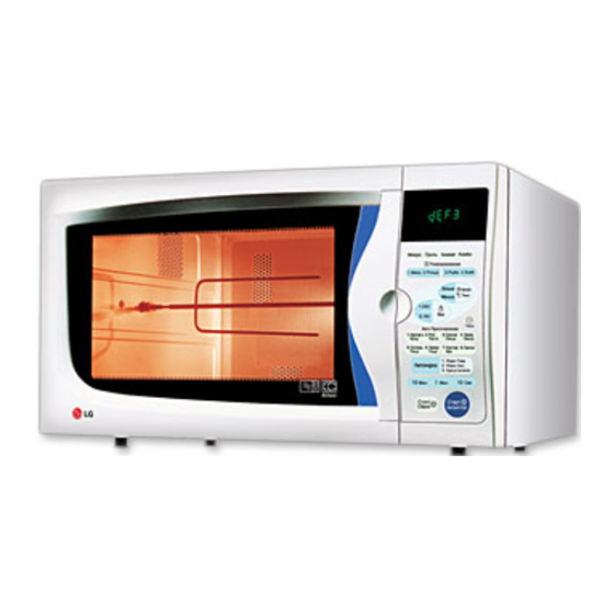
SPECIFICATIONS ITEM DESCRIPTION MODEL MC-804AR Power Requirement 230V AC50Hz Single phase, 3 wire grounded Microwave 1,350W Grill 1,250W Convection 1,350W (MAX. 2,550W) Combination 2,650W Power Output 850W full microwave power(IEC705) Microwave Frequency 2,450MHz Magnetron 2M214 - 39F, 2M254J, 2M218J Timer 99min. - Page 3 OPERATING INSTRUCTIONS Features Oven front face Window door screen Door seal Control panel ROTISSERIE-BAR Shaft Latch Metal tray Glass turntable Rotating ring ROTISSERIE-HANDLE Grill rack Convection rack Control Panel 1. Grill: To select grill cooking. 2. MICRO POWER: To select micro power cooking and cooking power levels.
-
Page 4: Operating Sequence
Operating Sequence The following is a description of component functions 6. Combination cooking during oven operation. Desired convection 1. Setting the clock Combination temp (100 C~250 Plug the power Set the cord into an Clock correct hour electric outlet Grill Set the correct Clock... -
Page 5: Schematic Diagram
SCHEMATIC DIAGRAM... -
Page 6: Circuit Description
Circuit Description and relay 2 and/or secondary switch fail to open, the • As the door is closed, the contact of MONITOR 10A fuse opens due to the large current surge caused SWITCH opens. This switch creates the short circuit to by the monitor switch activation which in turn stops blow 10 A fuse during operation under abnormal magnetron, oscillation. - Page 7 MICROWAVE/GRILL CONVECTION OVEN SERVICE MANUAL MODEL : MC-804AR CAUTION BEFORE SERVICING THE UNIT, READ THE SAFETY PRECAUTIONS IN THIS MANUAL.
-
Page 8: Service Information
SERVICE INFORMATION Tools and Measuring Instruments NECESSARY TOOLS NECESSARY MEASURING INSTRUMENTS Tools normally used for TV servicing are sufficient. Standard tools are listed below. • TESTER (VOLTS-DC, AC, Multmeter) • Diagonal pliers • Microwave survey meter • Long nose pliers —Holaday H1-1500, Hi-1501 •... -
Page 9: Measurement With The Outer Case Removed
MEASUREMENT WITH THE OUTER NOTES WHEN MEASURING CASE REMOVED • Do not exceed meter full scale deflection. • The test probe must be removed no faster than, • When you replace the magnetron, measure microwave 1 inch/sec (2.5 cm/sec) along the shaded area, energy leakage before the out case is installed and otherwise a false reading may result. -
Page 10: Measurement Of Microwave Power Output
Measurement of Microwave Power Output • The microwave power output P in watts is calculated • Microwave power output measurement is made with from the following formula: the microwave oven supplied at its rated voltage and 4187 X (∆T) operated at its maximum microwave power setting with a load of (1000 ±... - Page 11 Remove door D. DOOR GROSS ASSEMBLY REMOVAL 1) Open the door. 2) Remove the choke cover cap very carefully with a flat- Door seal plate blade screwdriver. CAUTION : Be careful not to damage door seal plate with the screwdriver. 3) Lift up and push the door.
-
Page 12: Magnetron Removal
2. When replacing the magnetron, be sure to install the E. MAGNETRON REMOVAL magnetron gasket in the correct position and be sure 1) Disconnect the leadwire from high voltage that the gasket is in good condition. transformer and high voltage capacitor. 3. -
Page 13: Oven Lamp Removal
F. NOISE FILTER ASS'Y HIGH VOLTAGE H.V. Transformer DIODE, HIGH VOLTAGE CAPACITOR, AND COOLING FAN MOTOR REMOVAL 1 ) Disconnect lead wires from the noise filter ass'y and remove screw securing the noise filter earth wire to the back plate. 2) Push two hook of the guide suction and lift up the rear of noise filter ass'y. -
Page 14: Turntable Motor Removal
J. TURNTABLE MOTOR REMOVAL K. INTERLOCK SYSTEM 1) Remove the turntable. 1) INTERLOCK MECHANISM The door lock mechanism is a device which has been 2) Remove the turntable shaft VERY CAREFULLY with specially designed to completely eliminate microwave a slotted screw driver. activity when the door is opened during cooking and 3) Lay the set down on its back. -
Page 15: Interlock Continuity Test
Interlock continuity Test WARNING : FOR CONTINUED PROTECTION AGAINST EXCESSIVE RADIATION EMISSION,REPLACE ONLY WITH IDENTICAL REPLACEMENT RARTS. TYPE NO. SZM-V 16-FA-63 OR VP-533A-OF FOR PRIMARY / SECONDARY SWITCH TYPE NO. SZM-V 16-FA-62 OR VP-532A-OF FOR MONITOR SWITCH A. PRIMARY INTERLOCK SWITCH TEST B. -
Page 16: Component Test Procedure
Component Test Procedure CAUTIONS 1. DISCONNECT THE POWER SUPPLY CORD FROM THE OUTLET WHENEVER REMOVING THE OUT CASE FROM THE UNIT. PROCEED WITH THE TEST ONLY AFTER DISCHARGING THE HIGH VOLTAGE CAPACITOR AND REMOVING THE WIRE LEADS FROM THE PRIMARY WINDING OF THE HIGH VOLTAGE TRANSFORMER. - Page 17 COMPONENTS TEST PROCEDURE RESULTS Antenna Gasket Chassis Filament Terminals NOTE : When testing the magnetron, be sure to install the magnetron gasket in the correct position and be sure that the gasket is in good condition. Measure the resistance. HIGH VOLTAGE Normal : Momentary indicates (Multi-meter scale : R x 1000) CAPACITOR...
- Page 18 COMPONENTS TEST PROCEDURE RESULTS Normal Abnormal FUSE Check for continuity of the switch with a (Wire leads removed.) Multi-meter. NOTE : If the fuse is blown, check the primary, the secondary, and the monitor switches, H.V.D. and H.V.C. before replacing the fuse. If the fuse is blown by improper switch operation replace the defective switch and the fuse at the same time.
- Page 19 COMPONENTS TEST PROCEDURE RESULTS CIRCULATION MOTOR Normal : COM-230V : Approx. 150 Ω Measure the resistance. COM-24V : Approx. 20 Ω (Wire leads removed) (Multi-meter scale : R x 1) Abnormal : Infinite or several ohm. (BN) 230V(BL) (YL) NOTE: ) = WIRE COLOR Measure the resistance.
- Page 20 COMPONENTS TEST PROCEDURE RESULTS Cooking Start RELAY 3,4 OF P.C.B (Disconnect the 7 pin connector from P.C.B) See Schematic Dagram on page 9) Relay 3 Relay 4 Cooking Start RELAY 2,3,4 OF P.C.B (Wire leads removed.) RY2 : Microwave RY3 : Grill RY4 : Convection Relay 3 Relay 4 Relay 2 Check continuity between...
-
Page 21: Troubleshooting Guide
Trouble Shooting Guide CAUTIONS 1. Check grounding before checking for other trouble. 2. Be careful of the high voltage circuit. 3. When checking the continuity of the switches or transformer, disconnect one lead wire from these parts and then check continuity without turning the power source on. 4. - Page 22 (TROUBLE 2) Oven does not at all even thought MOTOR and P.C.B program. TEST PROCEDURE OR CONDITION CAUSE CORRECTION No input can be Defective tact switch key of Test procedure tact switch programmed. P.C.B. key of P.C.B. Some inputs can not be Loose connection.
- Page 23 (TROUBLE 3) Oven does not operating microwave cooking TEST PROCEDURE OR CONDITION CAUSE CORRECTION Oven does not go into a Primary and secondary Test procedure primary and cook cycle when START key interlock switches defective secondary switches. is touched. or out of adjustment. Test procedure flat cable of Defective flat cable of P.C.B.
- Page 24 (TROUBLE 3) Oven does not operating microwave cooking TEST PROCEDURE OR CONDITION CAUSE CORRECTION Test procedure relay 2 of No microwave oscillation. Defective relay 2 of P.C.B. P.C.B. Defective high voltage Test procedure high voltage transformer. transformer. Defective high voltage Test procedure high voltage capacitor.
- Page 25 (TROUBLE 4) Oven does not operate convection cooking TEST PROCEDURE OR CONDITION CAUSE CORRECTION Defective circulation motor Check and repair C-Motor wire Convection indicator lights wire ass'y. ass'y. (COM:YL, 24V:BN, 230V:BL) but oven does not go into cook cycle when START key is touched.
- Page 26 (TROUBLE 5) Oven does not operating Grill cooking TEST PROCEDURE OR CONDITION CAUSE CORRECTION Test procedure relay 3 of Grill indicator lights Defective relay 3 of P.C.B. P.C.B. but oven does not go into cook cycle when START key is touched. Open or loose wire Check and repair wiring.
-
Page 27: Exploded View
EXPLODED VIEW INTRODUCTION OVEN CAVITY PARTS INTERIOR PARTS DOOR PARTS BASE PARTS LATCH BOARD PARTS CONTROL PANEL PARTS... -
Page 28: Door Parts
DOOR PARTS 13581A 15006A 13552A 13213A 14890A 14026A 14970A 13806D 13720D... -
Page 29: Control Panel Parts
CONTROL PANEL PARTS 268711 23572A 266381 WTR015 24781M... -
Page 30: Oven Cavity Parts
OVEN CAVITY PARTS WTT021 33112U 54974A WTT021 WTT011 348102 35300A WTP013 WMT002 34370Z 36549R 33550H 348101 35301A WTT010 33052M 35026C 35026G 34370T 33390M WTT011 33390G 34930R 35889A 34271A WTT011 34960T 34036W 33650R 36549S WTP013... -
Page 31: Latch Board Parts
LATCH BOARD PARTS 435001 466001 466003 WSZ085 44510A 466001 435011... -
Page 32: Interior Parts
INTERIOR PARTS 54975G 56322A 53551A 568772 WTT021 56411A WSZ062 948505 53504A WTT021 54810T 54975A 56930V 35300S 36549C 54350A 55900N WWP008 WSZ002 50FZZA WWS005 56201A WNH003 55900C WMT002 54974S WTT037 WTT028 WTP002 56549F 55900A 56930M WSZ002 50CZZH 948503 56324A 54810C 568771 948504 WTT028 WMP002... -
Page 33: Base Plate Parts
BASE PLATE PARTS 56170D 633031 633021 948501 WSZ062 WSZ002 647781 WTT030... -
Page 34: Schematic Diagram Of P.c.b
SCHEMATIC DIAGRAM OF P.C.B... -
Page 35: Printed Circuit Board
PRINTED CIRCUIT BOARD...