Bloomfield INTEGRITY 9012 Owner's Manual
Decanter coffee brewers
Hide thumbs
Also See for INTEGRITY 9012:
- Brochure (34 pages) ,
- Owner's manual (28 pages) ,
- Specifications (2 pages)
Table of Contents
Advertisement
Quick Links
2060 Cessna Dr, Suite 100
Vacaville, CA 95688
telephone: 707-448-5151
fax: 707-448-1521
www.bloomfieldworldwide.com
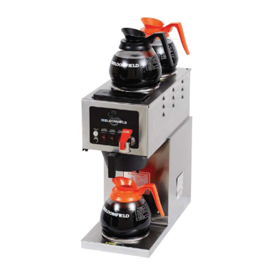
Model 9016 Brewers
with optional
8900-Series Glass Decanters
Rev M
2M-75815
p/n
OWNERS MANUAL
for
INTEGRITY™
DECANTER
COFFEE BREWERS
MODELS
9003
9012
9016
Includes:
Installation
Use & Care
Servicing Instructions
601
21
M601
0505
Advertisement
Table of Contents

Related Manuals for Bloomfield INTEGRITY 9012


Summary of Contents for Bloomfield INTEGRITY 9012
- Page 1 OWNERS MANUAL INTEGRITY™ 2060 Cessna Dr, Suite 100 Vacaville, CA 95688 DECANTER telephone: 707-448-5151 COFFEE BREWERS fax: 707-448-1521 www.bloomfieldworldwide.com MODELS 9003 9012 9016 Includes: Installation Model 9016 Brewers Use & Care with optional Servicing Instructions 8900-Series Glass Decanters Rev M 2M-75815 M601 0505...
-
Page 2: Warranty Statement
Bloomfield for its products are based upon the limitations in this warranty. Seller’s obligation under this warranty is limited to the repair of defects without charge by a Bloomfield Authorized Service Agency or one of its sub-agencies. This service will be provided on customer’s premises for non-portable models. -
Page 3: Table Of Contents
TABLE OF CONTENTS WARRANTY STATEMENT Thank You for purchasing this SPECIFICATIONS FEATURES & OPERATING CONTROLS PRECAUTIONS & GENERAL INFORMATION AGENCY APPROVAL INFORMATION INSTALLATION INSTRUCTIONS OPERATION BREWING COFFEE CLEANING INSTRUCTIONS TROUBLESHOOTING SUGGESTIONS SERVICING INSTRUCTIONS EXPLODED VIEWS & PARTS LISTS WIRING DIAGRAMS SPECIFICATIONS... -
Page 4: Features & Operating Controls
FEATURES AND OPERATING CONTROLS HOT WATER FAUCET (certain models) WATER LINE CONNECTION IL1614a Fig. 1 Features & Operating Controls... -
Page 5: Precautions & General Information
PRECAUTIONS AND GENERAL INFORMATION WARNING: ELECTRIC SHOCK HAZARD WARNING service personnel. Do not open any access panels which require the use of tools. Failure to heed this warning can result in electrical shock. WARNING: INJURY HAZARD WARNING all applicable electrical and plumbing codes. Failure could result in property damage and personal injury. -
Page 6: Installation Instructions
A flex line or loops of copper tubing will satisfy this operation of the brewer. requirement. See Figure 2 below. Bloomfield recommends 1/4” copper tubing for installation of less than 12 feet and 3/8” for more than 12 feet from a 1/2”... - Page 7 INSTALLATION INSTRUCTIONS (continued) NOTE: This equipment must In some areas, local codes require a backflow preventer (check be installed to comply with valve) to be installed on the inlet water line. If a backflow applicable federal, state and preventer is used, you must install a water hammer arrester in local plumbing codes and the incoming line, between the backflow preventer and the ordinances.
-
Page 8: Operation
OPERATION TANK VENT BASIN TUBE HOT WATER FAUCET FAUCET SHUT-OFF VALVE FAUCET WATER HEATING BREW COIL HEAD WATER TANK NEW-STYLE SOLENOID BREW CHAMBER COLD WATER INLET FITTING HOT WATER Fig. 4 Brewer Operation Diagram IL1617 IMPORTANT: START-UP Tank must be full of For initial start-up, or if the brewer has not been used for an water before connecting extended period of time:... - Page 9 OPERATION (continued) WATER HEATER Water temperature is sensed by a thermobulb inserted into the water tank. This temperature signal is fed to the thermostat, which controls line power to the heating element. The setpoint temperature is adjustable at the thermostat. The element is protected from over-temperature by a hi-limit thermostat.
-
Page 10: Brewing Coffee
BREWING COFFEE CAUTION: PREPARATION Place one (1) genuine Bloomfield BURN HAZARD PAPER paper filter in the brew chamber. FILTER Exposed surfaces of the Add a pre-measured amount of brewer, brew chamber and fresh coffee grounds. BREW decanter may be HOT to... -
Page 11: Cleaning Instructions
CLEANING INSTRUCTIONS PROCEDURE: Clean Coffee Brewer CAUTION: BURN HAZARD PRECAUTIONS: Disconnect brewer from electric power. Allow brewer to cool. Brewing and serving temperatures of coffee are FREQUENCY: Daily extremely hot. Hot coffee will cause TOOLS: Mild Detergent, Clean Soft Cloth or Sponge serious skin burns. -
Page 12: Troubleshooting Suggestions
Adjust amount of grounds Coffee level too high or low (automatic) Timer out of adjustment Adjust timer Too many filter papers or wrong filter Use one (1) genuine Bloomfield filter paper per brew Brew chamber overflows Brew chamber dispense hole plugged... -
Page 13: Servicing Instructions
SERVICING INSTRUCTIONS ACCESS PANELS CAUTION: SHOCK HAZARD Each warmer plate has a center stud which screws into a bracket. Warmer plates on Canadian brewers are secured with a nut. Opening access panels or Remove button plug on bottom of brewer to access nut on main removing warmer plates on this warmer. - Page 14 SERVICING INSTRUCTIONS (continued) TEMPERATURE ADJUSTMENT CAUTION: Unplug power cord or turn circuit breaker OFF. SHOCK HAZARD Remove top panel. These procedures involve Pull vent tube out of tank lid and insert a thermometer of known exposed electrical circuits. accuracy in vent hole. Reconnect brewer to electrical power. These procedures are to THERMOSTAT be performed by qualified...
- Page 15 SERVICING INSTRUCTIONS (continued) TIMER ADJUSTMENT IMPORTANT: Water pressure The amount of water dispensed automatically during a brew cycle must be between 20 p.s.i and is controlled by the timer. 90 p.s.i. flowing pressure. If water pressure exceeds this Place empty decanter under brew chamber. Press BREW value, or if water pressure button.
- Page 16 SERVICING INSTRUCTIONS (continued) IMPORTANT: When replacing REPLACE HEATING ELEMENT heating element, also replace Remove tank lid assembly as described on page 13. seal gaskets. Remove two hex nuts holding element to cover. Pull element from mounting holes. Reassemble in reverse order. REPLACE SOLENOID Symptom: Automatic brewer will not flow water;...
- Page 17 SERVICING INSTRUCTIONS (continued) REPLACE TIMER ASSEMBLY Unplug power cord or turn circuit breaker OFF. Remove front panel. Remove knob and three screws holding timer to bracket. Disconnect wiring to timer. Reassemble in reverse order. Adjust timer as described on page 13 REPLACE HOT WATER FAUCET COIL IMPORTANT: When replacing Symptom: Brewer drips continuously from brew head, except...
- Page 18 SERVICING INSTRUCTIONS (continued) PROCEDURE: Delime the Water Tank CAUTION: CHEMICAL BURN HAZARD PRECAUTIONS: Disconnect brewer from electric power. Allow brewer to cool. Deliming chemicals may be caustic. Wear appropriate protective gloves and goggles FREQUENCY: As required (Brewer slow to heat) during this procedure.
- Page 19 Should deliming hoses become necessary, Bloomfield recom- 8. Reinstall wiring to heating element and thermostat. Reinstall mends replacing the hoses. the hi-limit thermostat (if removed). For brewers with hot water faucet, reassemble faucet piping.
-
Page 20: Exploded Views & Parts Lists
EXPLODED VIEW: Main Assembly SEE DETAIL 18h 18j 18k Model: 9010 Integrity® In-Line Automatic Coffee Brewer Main Assembly SK2902... - Page 21 PARTS LIST: Main Assembly Model: 9003, 9010, 9012, 9016 Integrity® Inline Brewers Fig No. Part Number Description Application 9010, 9012, 9016 2C-70092 SCREW 8BX3/8 PH PAN HD SM 9003 2D-70090 PLATE CVR WRMR 1/4-28 2N-70091UL ELEM WARMER 120V 100W 120V, 120C, 9016D3F-240V, 9016D3FK-240 2N-70635UL ELEM WARMER 100W 240V/85W 230V, 230UK...
- Page 22 PARTS LIST: Main Assembly Continued Model: 9003, 9010, 9012, 9016 Integrity® Inline Brewers Fig No. Part Number Description Application 2P-Z16730 TIMER, 3 MIN. 120V 120V, 120C (except 9003) 2P-70054RO TIMER W/KNOB 2-MIN 240V 230V (except 9003) 9010, 9012, 9016, 9003-D3K-120 2P-70272 PLUG BUTTON 1/2 DIA 9003...
- Page 23 EXPLODED VIEW: Detail A From To Faucet Basin Spray Head Basin Vent From Solenoid DETAIL Hot Water Tank Assy w/ Hot Water Facuet SK2903...
- Page 24 PARTS LIST: Detail A Detail A: Tank Assembly Fig No. Part Number Description Application 2J-75681 HOSE BRAID 6MM X 299MM(11.7 9010, 9012, 9016 2V-70352 VALVE NEEDLE SEAT 9010, 9012, 9016 2E-70451 CONNECTOR BRASS 2V-70111 TUBE FORMED INLET ASSY 9010, 9012, 9016 2V-70104 TUBE OUTLET ASSY 10 7/16 9010, 9012, 9016...
-
Page 25: Wiring Diagrams
WIRING DIAGRAMS 9003... - Page 26 WIRING DIAGRAMS 9010...
- Page 27 WIRING DIAGRAMS 9016...
- Page 28 2060 Cessna Dr, Suite 100 Vacaville, CA 95688 phone (707)448-5151 fax (707)448-1521 www.bloomfieldworldwide.com...