Siemens RDE10.1DHW - Room Temperature Controller Manual
- User manual (8 pages) ,
- Operating instructions (4 pages)
Advertisement
- 2-position control with ON / OFF output for heating
- Independent ON / OFF control of DHW
- Operating modes: Auto, normal operation, energy saving and frost protection
- 7-day time switch and manual control
- Battery-powered DC 3 V (2 x 1.5 V AA)
Use
The RDE10.1DHW is used for the control of the room temperature in heating systems with independent control of DHW.
Typical applications:
- Residential apartments
For the control of the following plant components and of DHW:
- Thermal valves or zone valves
- Gas or oil burners
- Fans
- Pumps
- Heat exchanger
- Continuous-flow water heater
- Small water heating systems
Functions
Function diagram

T Room temperature
SD Switching differential
W Room temperature setpoint
Q14 Output signal for heating
Operating modes
The RDE10.1DHW provides auto, normal operation, energy saving (or OFF) or frost protection mode. The difference between normal operation and energy saving mode is merely the room temperature setpoint. The changeover from normal operation to energy saving or frost protection mode, or vice versa, is made by pressing a button.
In auto mode changeover between operating modes is accomplished automatically according to the 7-day switching pattern.
Normal operation
When normal operation is activated, symbol  appears on the display. The setpoint can be readjusted by pressing buttons
  ,
,  and
and  .
.
Energy saving or OFF
When energy saving mode is activated, symbol  appears on the display. The setpoint can be readjusted by pressing buttons
  , and .
In energy saving mode, the unit can also be switched to OFF. This is accomplished by selecting a setpoint of 5°C and then keeping button depressed for 4 seconds. In that case, symbol does not appear.
Frost protection
When frost protection mode is activated, symbol  appears on the display.
7-day time switch
The changeover between "normal" and "energy saving" temperature setpoints can take place either automatically ( ) or manually (, ), depending on the selection of the operating mode.
When pressing the operating mode button until appears on the display, changeover will take place automatically according to the selected switching pattern. A specific switching pattern can be selected for every weekday.
Factory setting:
| Day(s) | Normal operation | Energy saving mode |
| Mo (1) – Fr (5) | 6:00 – 8:00 h and 17:00 – 22:00 h | 22:00 – 6:00 h and 08:00 – 17:00 h |
| Sa (6) – Su (7) | 7:00 – 22:00 h | 22:00 – 7:00 h |
The current setpoint can be temporarily readjusted by pressing buttons and . The setpoint will then be reset to its initial value the next time automatic or manual changeover takes place.
When the operating mode button is set to or , the controller will maintain normal operation or energy saving mode respectively.
DHW mode
The RDE10.1DHW features independent control of DHW.
The following DHW operating modes can be selected:
Continuously ON: Symbol  appears on the display
Continuously OFF: No symbol on the display
Auto: Symbol  appears on the display, DHW is switched according to the selected switching pattern
Factory setting: Time switch for DHW
| Day(s) | DHW control ON | DHW control OFF |
| Mo (1) – Fr (5) | 6:00 – 8:00 h and 17:00 – 22:00 h | 22:00 – 6:00 h and 08:00 – 17:00 h |
| Sa (6) – Su (7) | 7:00 – 22:00 h | 22:00 – 7:00 h |
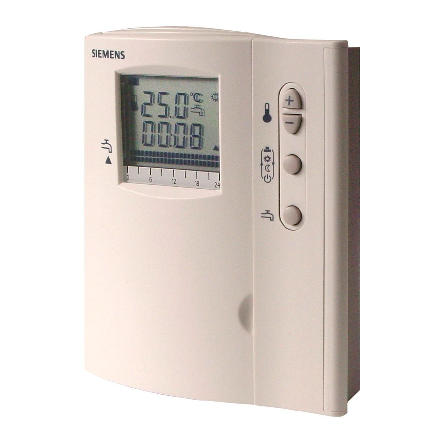
Display
The digital display shows the actual room temperature, the time of day, the weekday, the current switching pattern for heating, the switching pattern for DHW, and the symbol of the operating mode currently active. When the heating output is activated, the triangle symbol appears.
Display of the switching pattern is split up in upper and lower row.
When the segment is displayed and flashing, the DHW output is activated. When no segment is displayed, the DHW output is deactivated.
Upper row with switching pattern for DHW control

When the segment is displayed and flashing, the normal temperature setpoint is active. When no segment is displayed, the energy saving or frost protection temperature setpoint is active.
Lower row with switching pattern for heating

OFF mode and frost protection display

Backup
When taking out the batteries, the setpoints and the information required for operating mode changeover are memorized. However, the real time clock must be reset after the batteries are replaced.
Ordering
When ordering, please give name and type reference: Room temperature controller RDE10.1DHW.
Valve actuators are to be ordered as separate items.
Equipment combinations
| Type of unit | Type reference | Data sheet |
| Electromotoric ON / OFF actuator | SFA21... | 4863 |
| Thermal actuator (for radiator valve) | STA21... | 4893 |
| Thermal actuator (for small valve 2.5 mm) | STP21... | 4878 |
Accessories
| Description | Type reference |
| Adapter plate 120 x 120 mm for 4" x 4" conduit boxes | ARG70 |
| Adapter plate 96 x 120 mm for 2" x 4" conduit boxes | ARG70.1 |
| Adapter plate for surface wiring 112 x 130 mm | ARG70.2 |
Mechanical design
The controller consists of 2 parts:
- Plastic housing with digital display, which accommodates the electronics, the operating elements and the built-in room temperature sensor
- Mounting base
The housing engages in the mounting base and snaps on.
The base carries the screw terminals.

Legend
- Display of the room temperature in °C, or setpoints
- Current time of day using the 00:00... 23:59 format
- Current weekday from 1 (Monday) to 7 (Sunday)
- Current heating
![]() and DHW
and DHW ![]() switching pattern with flashing time pointer
switching pattern with flashing time pointer ![]() Symbol when the actual room temperature is displayed
Symbol when the actual room temperature is displayed![]() Button for operating mode
Button for operating mode![]() Button for DHW control
Button for DHW control![]() Selecting and leaving the setting mode for the DHW switching pattern
Selecting and leaving the setting mode for the DHW switching pattern![]() Symbol in automatic mode or when selecting the switching pattern
Symbol in automatic mode or when selecting the switching pattern![]() Heating ON
Heating ON![]() or
or ![]() will show when DHW heating is activaed
will show when DHW heating is activaed![]() Symbol indicating that batteries need to be replaced
Symbol indicating that batteries need to be replaced- Buttons for adjusting the setpoints, the time of day and the switching times
- Setting the weekday
- Setting the time of day
- Selecting and leaving the setting mode for the heating switching pattern
- Setpoint adjustment for energy saving mode
- Setpoint adjustment for normal operation
- Button for confirming the switching pattern settings
- Battery compartment
 and DHW
  Symbol when the actual room temperature is displayed
 Symbol indicating that batteries need to be replaced
Notes
The room temperature controller should be mounted in a location where the air temperature can be acquired as accurately as possible without getting adversely affected by direct solar radiation or other heat or refrigeration sources.
Mounting height is about 1.5 m above the floor.

The controller can be fitted to a recessed conduit box.

- Only authorized staff may open the unit.
![]()
AC 230 V! - The cables used must satisfy the insulation requirements with regard to mains potential

Mounting, installations and commissioning
When mounting the controller, fix the base first. Then, make the electrical connections and fit and secure the cover (also refer to the relevant Mounting Instructions).
The controller must be mounted on a flat wall and in compliance with local regulations. If there are thermostatic radiator valves in the reference room, they must be set to their fully open position.
Maintenance
The controller is maintenance-free.
Sensor calibration
If the temperature on the display does not agree with the room temperature effectively measured, the temperature sensor can be recalibrated. For that purpose, both buttons and  must be pressed simultaneously for 3 seconds. Then, the temperature displayed can be changed by a maximum of +/- 3 K by pressing the and buttons. 5 seconds after the last push of a button, the controller will automatically return to the normal operating state.
Change of batteries
If the battery symbol appears, the battery power is almost exhausted and the batteries should be replaced.
Reset
To make a reset, first press and hold the  button, then press the 2 buttons
  simultaneously for 3 seconds. All individual settings will be reset to their standard values.
Technical data
| Power supply | Operating voltage | DC 3 V (2 x 1.5 V AA Alkaline batteries) |
| Battery life (RDE10.1DHW) | > 1 year (AA Alkaline batteries) | |
| Control outputs | Heating valve or wall-hung boiler – Y1 | |
| Control output Q12 (NC contact) Rating RDE0.1DHW (AC 24...250 V) | max. 5(2) A | |
| Control output Q14 (NO contact) Rating RDE10.1DHW (AC 24...250 V) | max. 5(2) A | |
| DHW control – Y2 | ||
| Control output Q22 (NC contact) Rating RDE10.1DHW (AC 24...250 V) | max. 5(2) A | |
| Control output Q24 (NO contact) Rating RDE10.1DHW (AC 24...250 V) | max. 5(2) A | |
| Operational data | Switching differential SD | 1 K |
| Setpoint setting range | ||
| Normal operation | 5...35°C | |
| Energy saving | 0 (OFF) and 5...35°C | |
| Factory setting normal operation | 20°C | |
| Factory setting energy saving | 8°C | |
| Frost protection | 5°C (fixed) | |
| Resolution of settings and displays | ||
| Setpoints | 0.5°C | |
| Switching times | 60 min | |
| Actual temperature value displays | 0.5°C | |
| Time of day displays | 1 min | |
| Environmental conditions | Operation | to IEC 721-3-3 |
| Climatic conditions | class 3K5 | |
| Temperature | 0...+50°C | |
| Humidity | <95% r.h. | |
| Transport | to IEC 721-3-2 | |
| Climatic conditions | class 2K3 | |
| Temperature | -25...+60°C | |
| Humidity | <95% r. h. | |
| Mechanical conditions | class 2M2 | |
| Storage | to IEC 721-3-1 | |
| Climatic conditions | class 1K3 | |
| Temperature | -25...+60°C | |
| Humidity | <95% r. h. | |
| Standards |  conformity to conformity to | |
| EMC directive | 89/336/EEC | |
| Low-voltage directive | 73/23/EEC and 93/68/EEC | |
 C-Tick conformity to EMC emission standard C-Tick conformity to EMC emission standard | AS/NSZ 4251.1:1994 | |
| Product standards | ||
| Automatic electrical controls for household and similar use | EN 60 730 – 1 and EN 60 730–2-9 | |
| Electromagnetic compatibility | ||
| Emissions | EN 61 000–6-3 | |
| Immunity | EN 61 000–6-1 | |
| Safety class | II to EN 60730 | |
| Pollution class | normal | |
| Degree of protection of housing | IP30 to EN 60529 | |
| General | Connection terminals for | solid wires or prepared stranded wires. 2 x 1.5 mm2 or 1 x 2.5 mm2 (min. 0.5 mm2) |
| Weight | 0.21 kg | |
| Color of housing front | white, NCS S 0502-G (RAL 9003) | |
Connection diagram

Lx - Nx AC 24...250 V / max. 5 (2) A
Legend
Y1 Heating valve or wall-hung boiler
Y2 DHW heating equipment
Application examples

Room temperature controller with direct control of a gas-fired wall-hung boiler and independent control of DHW

Room temperature controller with direct control of a gas-fired floor-standing boiler and independent control of DHW

Room temperature controller with direct control of a heating circuit pump (precontrol by manual mixing valve) and independent control of DHW
Legend
F1 Thermal reset limit thermostat
F2 Safety limit thermostat
M1 Circulating pump
N1 RDE10.1DHW room temperatures controller
Y1 3-port valve with manual adjustment
Y2 Magnetic valve
DHW DHW heating equipment
Dimensions
Controller and base

© 2005 Siemens Switzerland Ltd Subject to alteration

Documents / ResourcesDownload manual
Here you can download full pdf version of manual, it may contain additional safety instructions, warranty information, FCC rules, etc.
Download Siemens RDE10.1DHW - Room Temperature Controller Manual
Advertisement
Thank you! Your question has been received!


Need Assistance?
Do you have a question about the RDE10.1DHW that isn't answered in the manual? Leave your question here.