
Summary of Contents for Marvin GX2472
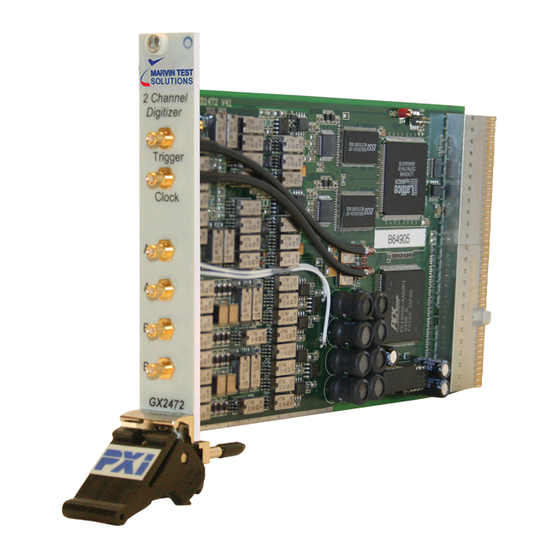
- Page 1 GX2472 Two Channel 70MS/s Waveform Digitizer Driver Manual Revision 1.2, May 2007 GEOTEST MARVIN TEST SYSTEMS, INC.
-
Page 3: Safety And Handling
Copyright Copyright © 2003-2007 by Geotest, Marvin Test Systems, Inc. All rights reserved. No part of this document can be reproduced, stored in a retrieval system, or transmitted, in any form or by any means, electronic, mechanical, photocopying, recording, or otherwise, without the prior written consent of Geotest. -
Page 4: Table Of Contents
Disclaimer..........................1 Copyright..........................1 Trademarks..........................1 Introduction ..........................4 1 GX2472 driver package ......................5 1.1 Installation ........................5 1.2 Uninstalling the low level driver ..................5 1.3 “Manual” installation of the low level driver ..............5 2 GX2472 DLL functions......................7 2.1 gx2472_AutoCalibrate (vi, mode, displayTime) .............. - Page 5 2.45 gx2472_SetLockMode(vi , lock ) ................. 19 2.46 gx2472_SetLoopMode (vi, loopMode) ................ 19 2.47 gx2472_SetOffsetCalCode(vi, code) ................19 2.48 gx2472_SetRange(vi , range ) ..................19 2.49 gx2472_SetSampleDivider (vi, sampleDividerValue) ..........20 2.50 gx2472_SetSoftwareTriggerStatus(vi , triggerstatus ) ..........20 2.51 gx2472_SetTriggerInput(vi , triggersource , triggermode ) .......... 20 2.52 gx2472_WriteCardId(vi , id ) ..................
-
Page 6: Introduction
PXI system, the card is provided with a software driver, utility software, a demo program for LabView and a calibration tool. The main part of the GX2472 driver consisst of a Windows dynamic link library, the gx2472.DLL For Labview users the driver also includes a LabView library with the gx2472.dll driver... -
Page 7: Gx2472 Driver Package
The PXI Kernel Driver cannot be installed on Windows95 or Windows NT. This selection will be disabled if one of these operating systems is detected. After installation shutdown the computer and place the GX2472 in the system. After turning on the computer the operation system should automatically detect the new hardware and install the low level driver. - Page 8 “gx2472.inf” The inf-subdirectory is a hidden directory. 2. If the pxi kernel mode driver is installed, copy also the gx2472.sys file. This file can be found in the directory \Drivers\Kernel\Winxx, where xx indicates the operating system. Copy this file to the Windows sub-directory \System\Drivers (e.g.
-
Page 9: Gx2472 Dll Functions
GX2472 DLL functions. This chapter describes the functions of the dll. Each function and its parameters are described in a table. The following parameter types are used: Type Details unsigned long 4-byte (32 bit) unsigned long double 8-byte floating point... -
Page 10: Gx2472_Codetovoltage (Vi, Adccode, Voltage)
The status code returned by a 0 to 2^32 long gx2472 driver function errorMessage char* The error message string gx2472_error_query( vi, errorCode, Message ) Description: Error Query is not supported by this instrument. This function only exists for compliance with the VXI Plug and Play specifications. -
Page 11: Gx2472_Findinstruments( Buslist, Devicelist, Count )
Parameters: Name Type Direction Description Value unsigned Instrument Handle 0 to 2^32 long errorCode unsigned 0 to 2^32 long Message char* string 2.7 gx2472_FindInstruments( buslist, devicelist, count ) Description: Returns the number of available instruments and a list with the bus and device number for each instrument. -
Page 12: Gx2472_Getcardconnection(Vi, Positiveinputconnection, Negativeinputconnection )
2.10 gx2472_GetCardConnection(vi, positiveInputConnection, negativeInputConnection ) Description: Get the status of the input relays. This routine returns the connection status from the active channel. There are 4 relays for each input. Each relay can be controlled with a bit: • Bit 1 (value 1 Hex) : Input relay; •... -
Page 13: Gx2472_Getdcoffsetlimitvoltages (Vi, Positivevoltage, Negativevoltage)
2.14 gx2472_GetDCOffsetLimitVoltages (vi, positiveVoltage, negativeVoltage) Description: Returns the DC Offset Limit Voltages. See function SetDCOffsetLimitVoltages(..). Parameters: Name Type Direction Description Value unsigned long Instrument Handle 0 to 2^32 positiveVoltage double* positive limit voltage 5 to 6 negativeVoltage double* negative limit voltage -5 to - 6 2.15 gx2472_GetDCOffsetVoltage(vi , voltage ) Description:... -
Page 14: Gx2472_Getloopmode (Vi, Loopmode)
Parameters: Name Type Direction Description Value unsigned long Instrument Handle 0 to 2^32 voltage double* measured voltage depends on range code unsigned long* adc code 0 to 2^14 average unsigned long averages 1 to 2^19 timeOut unsigned long time out 0 to 2^32 no timeout it time out is 0 2.19 gx2472_GetLoopMode (vi, loopMode) -
Page 15: Gx2472_Gettriggerinput (Vi, Triggersource, Triggermode)
Parameters: Name Type Direction Description Value unsigned long Instrument Handle 0 to 2^32 triggerstatus unsigned long * out current trigger status 0 = no channels triggered 1 = channel A triggered 2 = channel B triggered 3 = both channels triggered 2.24 gx2472_GetTriggerInput (vi, triggerSource, triggerMode) Description: This function returns the trigger source and trigger mode settings. -
Page 16: Gx2472_Memorytest (Vi, Level, Erroraddress)
2.26 gx2472_MemoryTest (vi, level, errorAddress) Description: This function performs a memory test. Parameters: Name Type Direction Description Value unsigned long Instrument Handle 0 to 2^32 level unsigned long level 0 = 1/10 of memory is tested 1 = total memory tested errorAddress unsigned long* error address... -
Page 17: Gx2472_Readinstrumentmemoryarray(Vi , Length , Buf32, Datainterpretation )
SetAddressCounter(). After this function call the address-counter is incremented with one step. Parameters: Name Type Direction Description Value unsigned long Instrument Handle 0 to 2^32 data unsigned long* read data 0 to 2^16 2.30 gx2472_ReadInstrumentMemoryArray(vi , length , buf32, dataInterpretation ) Description: Read length ram-places from the capture ram (of the active channel), starting from the current address-counter value. -
Page 18: Gx2472_Self_Test( Vi, Testresult, Errormessage )
This function always returns the defined value VI_WARN_NSUP_REV_QUERY. Parameters: Name Type Direction Description Value unsigned Instrument Handle 0 to 2^32 long driverRev char* Driver revision instrRev char* Instrument revision 2.34 gx2472_self_test( vi, testResult, errorMessage ) Description: Self Test is not supported by this instrument. It returns a defined value VI_WARN_NSUP_SELF_TEST. -
Page 19: Gx2472_Setclockoutputenable(Vi, Enable )
Name Type Direction Description Value unsigned long Instrument Handle 0 to 2^32 clockdivider unsigned long clock divider value 1 to 256 2.38 gx2472_SetClockOutputEnable(vi, enable ) Description: Enable the sample clock output. If annternal clock is selected and the clock output is enabled, the sample clock (clock/clockdivider) is available on the front clock connection. -
Page 20: Gx2472_Setdcoffsetlimitvoltages(Vi , Posvolt , Negvolt )
disconnect negative input 2 connect dc offset & negative input 2.42 gx2472_SetDCOffsetLimitVoltages(vi , posvolt , negvolt ) Description: Set limit voltages of dc offset DAC (of the selected channel). These voltages are necessary for a calibrated offset voltage. Procedure to determine limit voltages: •... -
Page 21: Gx2472_Setlockmode(Vi , Lock )
code unsigned long in code for gain cal. 0 to 2^10 2.45 gx2472_SetLockMode(vi , lock ) Description: Lock or unlock the memory access for active channel. A channel should be locked before the channel can be used to capture a signal. The memory cannot be accessed (by a controller) and the channel waits for a trigger in this mode. -
Page 22: Gx2472_Setsampledivider (Vi, Sampledividervalue)
2.49 gx2472_SetSampleDivider (vi, sampleDividerValue) Description: This function will program the sample divider. The sample divider determines how many samples will be stored. E.g. if the sample divider is 2, 1 of the 2 samples will be stored in the capture ram. Programming the sample divider will actually lower the sample rate, while the ADC sample clock is not lowered. -
Page 23: Gx2472_Writecardid(Vi , Id )
Store calibration data (of both channels) in serial EEPROM. This function should be called after a calibration procedure to store the calibration data in the on board serial EEPROM. Parameters: Name Type Direction Description Value unsigned long in Instrument Handle 0 to 2^32 2.52 gx2472_WriteCardId(vi , id ) Description:... -
Page 24: Gx2472_Writeinstrumentmemoryarray(Vi , Length , Buffer )
data unsigned long in data to write 0 to 2^14 2.56 gx2472_WriteInstrumentMemoryArray(vi , length , buffer ) Description: Write a buffer with length (32 bit) words to the (capture) ram of the active channel, starting at the current address counter position. The address-counter can be initialized with the function SetAddressCounter(). -
Page 25: Status Codes
Status codes This chapter will provides an overview of the possible status codes that can be returned by the dll-functions. General These codes can be returned by both VISA and non-visa driver functions. Completion without error: Constant name Value Description VI_SUCCESS No error(s) General error codes:...