Table of Contents
Advertisement
Quick Links
Manual 238-51617-00B
High EF
Atmospheric Vent Gas Water Heater
SERVICE
MANUAL
Troubleshooting Guide
and Instructions for Service
(To be performed ONLY by
qualified service providers)
Models Covered
by This Manual:
RG2F40S*(N,X)
RG2F50S*(N,X)
(*) Denotes Warranty Years
Save this manual for future reference
Advertisement
Table of Contents

Related Manuals for Bradford White High EF RG2F40S Series


Summary of Contents for Bradford White High EF RG2F40S Series
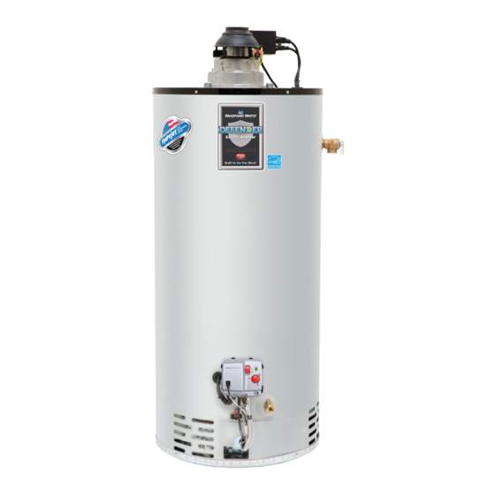
- Page 1 High EF Atmospheric Vent Gas Water Heater SERVICE MANUAL Troubleshooting Guide and Instructions for Service (To be performed ONLY by qualified service providers) Models Covered by This Manual: RG2F40S*(N,X) RG2F50S*(N,X) (*) Denotes Warranty Years Manual 238-51617-00B Save this manual for future reference...
-
Page 2: Table Of Contents
Table of Contents Section Page Introduction ______________________________________________ 5 How to Use this Manual _____________________________________ 6 Tools Required for Service ___________________________________ 6 Specifications _____________________________________________ 7 Sequence of Operation _____________________________________ 9 Power Up Sequence Normal Heating Sequence Abnormal Operation Troubleshooting __________________________________________ 13 Burner Maintenance _______________________________________ 15 Burner Inspection Burner Cleaning Procedure... - Page 3 WARNING If the information in these instructions is not followed exactly, a fire or explosion may result causing property damage, personal injury, or death. What to do if you smell gas: Do not try to light any appliance Do not touch any electrical switch; do not use any phone in your building Immediately call your gas supplier from a neighbor’s phone.
- Page 4 WARNING Water heaters are heat producing appliances. To avoid damage or injury, do not store materials against the water heater or any of its components. Use proper care to avoid unnecessary contact, especially by children, with the water heater and its components. Under no circumstances must flammable materials, such as gasoline or paint thinner be used or stored in the vicinity of this water heater or in any location in which the fumes could reach the water heater.
-
Page 5: Introduction
Introduction Page 5... -
Page 6: How To Use This Manual
How to Use this Manual Page 6... -
Page 7: Specifications
Specifications Page 7... - Page 8 Specifications Control Timings Ignition State Timing Pre-purge 15 seconds Trial for Ignition 90 seconds Flame Stabilization Period 3 seconds Interpurge 15 seconds 1.5 seconds (2 second maximum; 1 second mini- Flame Failure Response Time mum) Postpurge 15 seconds Pressure Switch Fault Delay (failed open/close) Retry after 2 minutes Soft Lockout Retry after 5 minutes...
-
Page 9: Sequence Of Operation
Sequence of Operation Page 9... - Page 10 Sequence of Operation Page 10...
- Page 11 Sequence of Operation Page 11...
- Page 12 Sequence of Operation Page 12...
-
Page 13: Troubleshooting
Troubleshooting Observe the green LED on the water heater gas control. Status codes are displayed with a 3 second pause before repeating. Once the status code is known, check and repair the water heater, as recommended in the table below. Page 13... - Page 14 Troubleshooting Page 14...
-
Page 15: Burner Maintenance
Burner Maintenance Gas control power switch Blower (water heater) power cord Outer door Page 15... - Page 16 Burner Maintenance (4) 1/4” hex drive screws Right side inner door Pilot and main feed- lines Gas control Spark igniter/flame sensor wire Burner assembly Burner surface area and burner ports Main burner orifice Main feedline 1/2” wrench Page 16...
-
Page 17: Pilot Maintenance
Pilot Maintenance Gas control power switch Blower (water heater) power cord Outer door (4) 1/4” hex drive screws Right side inner door Pilot and main feed- lines Page 17... - Page 18 Pilot Maintenance Gas control Spark igniter/flame sensor wire Burner assembly Pilot assembly 1/4” nut driver Multi-meter Page 18...
-
Page 19: Blower Replacement
Blower Replacement Gas control power switch Blower (water heater) power cord Page 19... - Page 20 Blower Replacement Vent system Draft hood Blower Cord sets 1/4” nut driver Blower Top of water heater Water heater tank flue Page 20...
-
Page 21: Gas Control Testing & Replacement
Gas Control Testing & Replacement WARNING Stored water may be HOT when performing the following steps in this procedure. Take necessary precaution to prevent personal injury. Page 21... -
Page 22: Gas Control Removal
Gas Control Testing & Replacement Gas control power switch Blower (water heater) power cord Pilot and main feed- lines Gas control Spark igniter/flame sensor wire Wire harnesses Page 22... -
Page 23: Flammable Vapor Sensor Testing
120 VAC Circuit Trace CAUTION Do not use standard multi-meter probes for this testing. Doing so will damage the con- nector. Use special pin type electronic probes or small diameter wire pins inserted into connector. Gas control power switch FVS/RTS harness Page 23... -
Page 24: Diptube Inspection
Diptube Inspection Page 24... -
Page 25: Anode Inspection
Anode Inspection WARNING Water heater components and stored water may be HOT when performing the following steps in this procedure. Take necessary precaution to prevent personal injury. Gas control power switch Page 25... - Page 26 Anode Inspection Blower (water heater) power cord Vent system Draft hood Blower Cord sets 1/4” nut driver Page 26...
-
Page 27: Blower Removal
Blower Removal Blower Top of water heater Water heater tank flue Flue baffle Page 27... -
Page 28: Inner Door Removal
Inner Door Removal Gas control power switch Blower (water heater) power cord Outer door (4) 1/4” hex drive screws Right side inner door Page 28... - Page 29 Inner Door Removal Left side inner door 1/4” hex drive screws Connectors attached to reset- table thermal switch Page 29...
-
Page 30: Inner Door Gasket Replacement
Inner Door Gasket Replacement WARNING If the information in these instructions is not followed exactly, a fire or explosion may re- sult causing property damage, personal injury, or death. Gasket Overlap must be as shown + 1/32 Enlarged view of flange area Recommended pattern for RTV sealant Gasket Overlap must be as... -
Page 31: Inner Door Installation
Inner Door Installation WARNING Stripped fastener connections may allow for an inner door seal breach. A seal breach may result in a fire or explosion, causing property damage, personal injury, or death. Do not over tighten screws. If a fastener connection is stripped, contact the manufacturer listed on the water heater rating plate. -
Page 32: Pressure Switch Testing & Replacement
Pressure Switch Testing Gas control power switch Blower (water heater) power cord Cord sets Slotted screwdriver Blower junction box Junction box screws Pressure switch tubing Junction box cover Page 32... - Page 33 Pressure Switch Testing Pressure switch screws Pressure switch Multi-meter leads Page 33...
-
Page 34: Arrestor Cleaning
Arrestor Cleaning Page 34... -
Page 35: Common Terms
Common Terms °C Degrees Centigrade °F Degrees Fahrenheit Page 35... -
Page 36: Parts List
Parts List PART NAME AND DESCRIPTION Page 36... - Page 40 905-636-0666 Warranty bwccwarranty@bradfordwhite.com Technical Support bwcctech@bradfordwhite.com Service Parts orders@bradfordwhitecanada.com Orders ca.orders@bradfordwhite.com For U.S. and Canada field service, contact your professional installer or local Bradford White sales representative. International General Contact international@bradfordwhite.com www.bradfordwhite.com ©2022, Bradford White Corporation, USA. All rights reserved.