Table of Contents
Advertisement
Quick Links
OPERATION MANUAL
TM
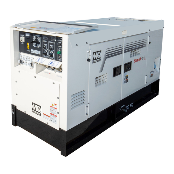
MODEL DLW500ESA4
WELDER/GENERATOR
(ISUZU 4LE2T DIESEL ENGINE)
INSTRUCTION MANUAL NO. D6844301434
Revision #0 (01/13/23)
To find the latest revision of this publication
or associated parts manual, visit our
website at:
www.multiquip.com
THIS MANUAL MUST ACCOMPANY THE EQUIPMENT AT ALL TIMES.
Advertisement
Table of Contents

Related Manuals for MULTIQUIP SmartStick DLW500ESA4

Summary of Contents for MULTIQUIP SmartStick DLW500ESA4
- Page 1 MODEL DLW500ESA4 WELDER/GENERATOR (ISUZU 4LE2T DIESEL ENGINE) INSTRUCTION MANUAL NO. D6844301434 Revision #0 (01/13/23) To find the latest revision of this publication or associated parts manual, visit our website at: www.multiquip.com THIS MANUAL MUST ACCOMPANY THE EQUIPMENT AT ALL TIMES.
-
Page 2: Proposition 65 Warning
PROPOSITION 65 WARNING PAGE 2 — DLW500ESA4 WELDER/GENERATOR • OPERATION MANUAL — REV. # 0 (01/13/23) -
Page 3: Reporting Safety Defects
If you believe that your vehicle has a defect that could cause a crash or could cause injury or death, you should immediately inform the National Highway Traffi c Safety Administration (NHTSA) in addition to notifying Multiquip Inc. at 1-800-421-1244. -
Page 4: Table Of Contents
TABLE OF CONTENTS DLW500ESA4 Welder-Generator Proposition 65 Warning ........... 2 Reporting Safety Defects ......... 3 Safety Information ..........5-12 Specifications (Welder-Generator) ......13 Specifications (Fuel Consumption) ......14 Dimensions ............15 Installation ............16-17 General Information ..........18 Welding Polarity And Duty Cycle ......19 Welding Terms ............ -
Page 5: Safety Information
SAFETY INFORMATION DO NOT operate or service the equipment before reading Potential hazards associated with the operation of this the entire manual. Safety precautions should be followed equipment will be referenced with hazard symbols which at all times when operating this equipment. may appear throughout this manual in conjunction with Failure to read and understand the safety safety messages. - Page 6 Unauthorized equipment modifi cation will void all warranties. „ NEVER use accessories or attachments that are not recommended by Multiquip for this equipment. Damage „ NEVER operate this equipment when not to the equipment and/or injury to user may result.
- Page 7 SAFETY INFORMATION WELDER SAFETY „ DO NOT touch output terminals during operation. Contact with output terminals during operation can cause DANGER electrocution, electrical shock or burn. „ NEVER install or operate the welder- „ Remove any combustibles, such as a butane lighter or generator in an explosive atmosphere or matches, from your person before doing any welding.
- Page 8 SAFETY INFORMATION CAUTION NOTICE „ Electric current flowing through any „ Electromagnetic energy can interfere conductor causes localized Electro with sensitive electronic equipment such Magnetic Fields (EMF). Welding current as microprocessors, computers and creates EMF fi elds around welding cables computer-driven equipment such as robots.
- Page 9 SAFETY INFORMATION ENGINE SAFETY NOTICE DANGER „ NEVER run engine without an air fi lter or with a dirty air fi lter. Severe engine damage may occur. Service air fi lter „ The engine fuel exhaust gases contain poisonous carbon frequently to prevent engine malfunction.
- Page 10 SAFETY INFORMATION FUEL SAFETY ELECTRICAL SAFETY DANGER DANGER „ DO NOT add fuel to equipment if it is placed inside truck „ Turn welder-generator and all circuit breakers OFF bed with plastic liner. Possibility exists of explosion or before performing maintenance on the generator or fi re due to static electricity.
- Page 11 „ For portable and vehicle-mounted welder-generators, CAUTION Multiquip recognizes the guidance provided in NEC „ ALWAYS disconnect the NEGATIVE battery terminal Handbook Article 250.34 Parts A and B, and 29 CFR before performing service on the generator.
- Page 12 SAFETY INFORMATION „ Use one point suspension hook and lift straight upwards. „ When the life cycle of this equipment is over, it is recommended that the unit frame and all other metal parts be sent to a recycling center. Metal recycling involves the collection of metal from discarded products and its transformation into raw materials to use in manufacturing a new product.
-
Page 13: Specifications (Welder-Generator)
SPECIFICATIONS (WELDER-GENERATOR) Table 1. Welding Generator Specifications CC Mode CV Mode High Speed Low Speed High Speed Low Speed Single Dual Single Dual Single Dual Single Dual Rated Output 17.1 kW 7.5 kW 7.5 kW 4.9 kW 16.4 kW 6.6 kW 6.6 kW 4.1 kW Rated Current... -
Page 14: Specifications (Fuel Consumption)
SPECIFICATIONS (FUEL CONSUMPTION) Table 5. Fuel Consumption No Load High (1800 rpm) Low (1200 rpm) Fuel Consumption 0.47 0.23 gal/hr. (llters/hr.) (1.77) (0.87) High (1800 rpm) Amperes Fuel Consumption 0.60 0.84 1.15 1.59 gal/hr. (llters/hr.) (2.27) (3.17) (4.35) (6.00) Low (1200 rpm) Amperes Fuel Consumption 0.30... -
Page 15: Dimensions
DIMENSIONS MAXIMUM LIFTING POINT TOP VIEW 3,030 lbs. (1,374 kg) Power Source Professionals. SIDE VIEW Table 6. Dimensions Reference Letter Dimension in. (mm) 24.21 (615) 24.21 (615) FRONT VIEW 23.62 (600) 23.62 (600) 44.48 (1130) 80.11 (2035) 16.92 (430) 32.67 (830) Figure 2. -
Page 16: Installation
INSTALLATION CONNECTING THE GROUND The ground cable should be #8 size wire (aluminum) minimum. If copper wire is used, #10 size wire minimum Consult with local Electrical and Safety Codes for proper should be used. connection based on condition of use. Connect one end of the ground cable terminal to the welder- EXAMPLE of how to ground the unit if the condition generator ground point (Figure 3). - Page 17 INSTALLATION OUTDOOR INSTALLATION WELDER-GENERATOR GROUNDING NOTICE If possible install the welder-generator in a area that is free of debris, bystanders, and overhead obstructions. Make The Occupational Safety and Health Administration sure the welder-generator is on secure level ground so (OSHA) and the National Electrical Code (NEC) that it cannot slide or shift around.
-
Page 18: General Information
GENERAL INFORMATION OUTPUT TERMINAL PANEL When used in single mode applications, Multiquip’s Model DLW500ESA4 Whisper Weld™ is a 500 amp DC welder. „ 120 VAC GFCI Receptacle (5-20R) Dual mode applications provide 250 amps at each of the A and B welding terminals. -
Page 19: Welding Polarity And Duty Cycle
WELDING POLARITY AND DUTY CYCLE WELDING POLARITY Table 7. 10-Minute Duty Cycle Welding Polarity indicates the direction of the current flow in that Duty Welding Cool Down Current circuit. Since DC current moves in only one direction, Cycle % ON Time (Min.) Time (Min.) (Amps) polarity is important because the flow of current must be... -
Page 20: Welding Terms
(Note: ARC Voltage – The voltage across the welding arc. Unlike competitive models, no parallel box is needed with Multiquip's welder-generators.) ARC Blow – The deflection of an electric arc from its normal path because of magnetic forces. -
Page 21: Components Welder/Generator
COMPONENTS WELDER/GENERATOR Figure 4. Welder-Generator Components 1. Engine Control Module (ECM) – An embedded 9. A/B DC Welding Output Terminals – Connect the DC electronic control system that controls various engine welding cables to these terminals. Note the polarity operating functions. marked on the welder-generator terminals. - Page 22 COMPONENTS WELDER/GENERATOR (CONT'D.) Figure 5. Welder-Generator Components (Continued) 6. Frame Ground Lug — Connect a ground strap 1. Radiator — Holds coolant/water necessary to keep between this lug and a ground rod. Make sure that the the engine at a safe operating temperature. Remove ground rod is inserted deep into the ground to provide this cap to add water/antifreeze when cool.
-
Page 23: Engine Components
ENGINE COMPONENTS Figure 6. Isuzu 4LE2T Basic Engine Components INITIAL SERVICING 8. Turbocharger — Provides pressurized intake air to the The engine (Figure 6) must be checked for proper lubrication cylinder by means of a turbine energized by exhaust and filled with fuel prior to operation. Refer to the manufacturer's gas that rotates the blower. -
Page 24: Power Receptacles
POWER RECEPTACLES POWER RECEPTACLES SINGLE PHASE LOAD Located on the side of the welder/generator are the Always be sure to check the nameplate on the welder- auxilliary power receptacles. These power receptacles are generator and equipment to insure the wattage, amperage, described below. -
Page 25: Control Panel
8. Diagnostic Lamp – When lit (ON) indicates that an turn the generator OFF and consult your authorized engine fault has occured. Reference Figure 100 and Multiquip service dealer. Figure 101. 2. Single/Dual Selector Switch – Place this switch in 9. - Page 26 CONTROL PANEL (CONT'D.) DC WELD METER 0D0-A-B HOUR METER Display Change Welding Welding ON (HOLD) TERMINAL: A TERMINAL: B Fuel Level ENGINE DIAGNOSIS IDLE STOP MONITOR (FUEL PUMP) AC CIRCUIT BREAKER Idle stop will not work when lamp is lit SINGLE DUAL WARNING LAMP...
- Page 27 CONTROL PANEL (CONT'D.) DC WELD METER 0D0-A-B HOUR METER Display Change Welding Welding ON (HOLD) TERMINAL: A TERMINAL: B Fuel Level ENGINE DIAGNOSIS IDLE STOP MONITOR (FUEL PUMP) AC CIRCUIT BREAKER Idle stop will not work when lamp is lit SINGLE DUAL Unit will not restart when lamp is blinking.
-
Page 28: Inspection
INSPECTION LUBRICATION OIL REFILLING THE FUEL SYSTEM Fill the engine crankcase with lubricating oil through the CAUTION filler hole, but DO NOT overfill. Make sure the generator is ONLY properly trained personnel who have read level and verify that the oil level is maintained between the and understand this section should refill the fuel tank two notches (Figure 12) on the dipstick. - Page 29 INSPECTION COOLANT (ANTIFREEZE/SUMMER COOLANT/ Table 14. Coolant Capacity WATER) Engine and Radiator 2.35 gal (8.9 liters) Isuzu recommends antifreeze/summer coolant for use in their Reserve Tank .22 gal (.832 liters) engines, which can be purchased in concentrate (and mixed with 50% demineralized water) or pre-diluted. See the Isuzu Operation in Freezing Weather Engine Owner’s Manual for further details.
- Page 30 INSPECTION FAN BELT TENSION BATTERY A slack fan belt may contribute to overheating or to This unit is of negative ground DO NOT connect in reverse. insufficient charging of the battery. Inspect the fan belt for Always maintain battery fluid level between the specified damage, wear and adjust it in accordance with the Kubota marks.
-
Page 31: Setup
SETUP SELECTING THE WELDING CABLE Table 17. Polarities and Applications Polarity Welding Method Typical Applications The welding cable should be larger in size as it becomes longer or its current becomes higher. Prepare a cable with Arc welding for steel material (+)...Grounding (base metal) Straight of general structures, and for... - Page 32 SETUP WARNING Table 18. Current Range/Electrode Size (Single Mode Operation) When operating the welder in dual mode, NEVER connect High the positive and negative terminals (Figure 20) from the A 1200 rpm 1800 rpm and B sides together. Current/ 30~280A 30~500A Range Amps This condition may cause the voltage between the welding...
- Page 33 SETUP 2. Select the appropriate welding wire size depending on the application as referenced in the wire feeder instruction manual. 3. After the correct wire size has been determined, install wire spool onto wire feeder. 4. Adjust the CV voltage regulator for the desired DC voltage to the wire feeder.
-
Page 34: Local Operation
LOCAL OPERATION Before starting the welder-generator, the pre-inspection 2. In addition, there are four circuit breakers (Figure 24) safety checks must be completed. In addition, do a general provided to protect the GFCI and auxiliary receptacles from overload. Make sure to switch all circuit breakers survey of the area surrounding the machine making sure the area is safe, air vents of the machine are not blocked to the OFF position prior to starting the welder-... - Page 35 LOCAL OPERATION NOTICE DO NOT operate this equipment with the enclosure doors open. Operating the unit with the doors open during operation will effect the internal cooling air-flow Figure 30. Hour Meter (Run Position) of the machine and will allow foreign substances (e.g. dust and dirt) to be drawn into the unit.
- Page 36 LOCAL OPERATION 2. For CC welding, place the terminal A welding mode 12. When the pre-heating time has been completed, engine cranking will begin and the engine will be started. rocker switch in the CC position (down). NOTICE All pre-heating and cranking are automatic. The pre- heating time and cranking times are automatically controlled by the temperature sensor located on the unit.
- Page 37 LOCAL OPERATION 6. The selected current (amps) will be displayed on the NOTICE DC weld meter. The example shown in Figure 39 is for If the welding work requires a current of 240 amps or less a constant current value of 135 amps. for single mode applications, place the e-mode selector switch in the high/low or high position if bead appearance or welding faults are a concern.
- Page 38 LOCAL OPERATION ADJUSTMENT OF WELDING REGULATION NORMAL The welding voltage/current curves (Figure 41) are obtained when the welding regulation control knob is turned fully counterclockwise (constant current) as shown in Figure 42. Welding Regulation (Constant Current) CONSTANT DROOP WELDING CURRENT EXAMPLE: WELDING CURRENT 100A REGULATION Figure 42.
- Page 39 LOCAL OPERATION Welding Regulation (Normal) If the welding current is higher, it is affected more by the welding cable voltage drop and if the cable is long When the welding regulation control knob is placed in the and has a small diameter, the welding output current The short-circuit current is normal position (Figure 43).
- Page 40 LOCAL OPERATION Welding Regulation (Droop) DUAL MODE WELDING (CC) Drooping is defined as when the terminal voltage of the NOTICE welding unit decreases the welding current increases NEVER switch the single/dual selector switch when When the welding regulation control knob is placed in the welding.
- Page 41 LOCAL OPERATION CV Welding Table 23. Voltage Range/Engine Speed 1. For CV welding, place the welding mode rocker switch (Single Mode Operation) (Figure 47) in the CV position. e Mode High Selector 1200 rpm 1800 rpm Switch 14~29 VDC — See Notes High/Low See Notes...
- Page 42 LOCAL OPERATION Idle Stop Function 4. Using the welding voltage control knob (Figure 50) adjust the voltage to the desired setting as referenced NOTICE in Table 23 (Single Mode) or Table 24 (Dual Mode). The idle stop function when selected allows the welder- generator to be started or stopped remotely.
- Page 43 LOCAL OPERATION RESTARTING FROM IDLE STOP (WELDING SIDE) 3. If any of the status lamps as referenced in Figure 52 are ON, correct the problem before using the idle stop This section will describe how the welder detects the restart function.
- Page 44 LOCAL OPERATION RESTARTING FROM IDLE STOP (GENERATOR SIDE) NOTICE This section will describe how the welder detects the restart Make sure the ON/OFF switch on the power tool is signal when idle stop selector switch has been placed in always placed in the OFF position after it has been the ON position (generator side).
- Page 45 LOCAL OPERATION NORMAL SHUTDOWN PROCEDURE 5. Remove all loads from the generator receptacles. 6. Remove any welding cables attached to the welding To shutdown the generator, use the following procedure: terminals. 1. Place the main circuit breaker (CB1) and auxiliary 7.
-
Page 46: Remote Operation
REMOTE OPERATION REMOTE OPERATION NOTICE The remote function when selected allows the welder- generator to be started or stopped remotely. Warning signs should be posted around the equipment indicating that the equiment can start without warning. All children LOCAL and unauthorized personnel should be kept away when LN-25 PRO REMOTE VOLTAGE the equipment is operating in this mode. - Page 47 REMOTE OPERATION When a wire feeder (Figure 66) is connected to the 14P NOTICE receptacle on the generator/welder via a control cable Reference the wire feeder owner's manual when remote and the local/remote weld output switch is placed in welding is required. Control cable is supplied with wire the REMOTE position, the welding voltage output is in feeder.
- Page 48 REMOTE OPERATION Switch Settings (Local/Remote) Reference Figure 70 for the various switch and dial settings when using the generator/welder and external wire feeder, WIRE REMOTE RECEPTACLE NOT AVAILABLE TERMINAL : A WELDING OUTPUT TERMINAL NORMAL ACTIVE LN-25 PRO WORK WIRE FEEDER CONSTANT DROOP WELDING...
-
Page 49: Maintenance
MAINTENANCE 500 Hrs 3000 Hrs 10 Hrs Table 25. Inspection/Maintenance 250 Hrs or Every or Every OTHER DAILY 12 Months 36 Months Check Engine Oil and Coolant Levels Check Fuel Filter Check Air Cleaner/Element Clean or Replace Air Cleaner/Element* As Required Check for Leaks/Hoses/Clamps Check for Loosening of Parts Change Engine Oil and Oil Filter *... - Page 50 MAINTENANCE GENERAL INSPECTION NOTICE Prior to each use, the generator should be cleaned and Operating the engine with loose or damaged air cleaner inspected for deficiencies. Check for loose, missing or components could allow unfiltered air into the engine damaged nuts, bolts or other fasteners. Also check for causing premature wear and failure.
- Page 51 MAINTENANCE FUEL FILTER ELEMENT REPLACEMENT DRAINING THE FUEL FILTER ELEMENT 1. Use a filter wrench to remove the element case NOTICE (Figure 73) from the fuel filter body. Inspect the fuel filter daily. If the fuel filter (Figure 57) has collected a significant amount of water and sediment at the bottom of the cup, it should be drained off immediately.
- Page 52 MAINTENANCE ELECTROMAGNETIC FUEL PUMP (500 HOURS) CLEANING INSIDE THE FUEL TANK The filter inside the fuel pump (Figure 74) is either a paper If necessary, drain the fuel inside the fuel tank completely. type or steel mesh type depending on the fuel pump type. Using a spray washer (Figure 75) wash out any deposits Clean or replace the fuel pump filter as follows: or debris that have accumulated inside the fuel tank.
- Page 53 MAINTENANCE DRIVE BELT (DAILY) ENGINE OIL (CHECK DAILY) LARRY Drive Belt Tension NOTICE Contact your country's Department of Public A slack drive belt (Figure 76) may contribute to overheating Works or recycling agency in your area and or insufficient charging of the battery. Adjust the drive belt arrange for proper disposal of any electrical in accordance with the Isuzu Operator’s manual.
- Page 54 MAINTENANCE DRAINING ENGINE OIL NOTICE 1. Run the engine until the engine coolant reaches a Refer to Table 27 for the suitable American Petroleum temperature of 140° (60°C) Turn the engine off. Institute (API) classification of engine oil according to the fuel type used (Low Sulfer, Ultra Low Sulfer or 2.
- Page 55 MAINTENANCE ENGINE OIL FILTER REPLACEMENT DRAINING ENGINE COOLANT 1. Clean the area around the lubricating oil filter head. WARNING 2. Using an oil filter wrench (Figure 79), remove engine DO NOT remove the pressure cap from the radiator oil filter. when the engine is hot! Wait until the coolant temperature is below 120°F (50°C) before removing pressure cap.
- Page 56 MAINTENANCE FLUSHING OUT RADIATOR AND REPLACING OPERATION IN FREEZING WEATHER COOLANT When operating in freezing weather, be certain the proper WARNING amount of antifreeze has been added as referenced in Table 28. DO NOT remove the pressure cap from the radiator when the engine is hot! Wait until Table 28.
- Page 57 MAINTENANCE Removing Water from the Fuel Tank TESTING THE GFCI SENSING MODULE 1. After prolonged use, water and other impurities If tripping of the main circuit breaker persists after a load is accumulate in the bottom of the tank. Occasionally replaced with a known good one (no short circuit), perform inspect the fuel tank for water contamination.
- Page 58 MAINTENANCE 5. Next, press the TEST button on the GFCI sensing module (Figure 86) and verify that the green POWER LED turns OFF and the red FAULT LED turns ON. PRESS GREEN POWER PRESS MANUAL RESET FAULT Figure 89. GFCI Sensing Module (Green LED ON Reset) MANUAL RESET 9.
- Page 59 MAINTENANCE TESTING THE GFCI RECEPTACLE 4. Plug a power tool such as an electric drill (Figure 93) into the GFCI receptacle. Squeeze the ON/OFF switch NOTICE on the drill and verify that the drill turns on.. The GFCI receptacle is designed to interrupt power when a ground fault exists to prevent injuries and shock hazards.
- Page 60 MAINTENANCE 2. In addition, the battery charge, oil pressure and water 8. If the status LED (Figure 95) is flashing (RED), temperature alarms will be displayed on the engine DO NOT use the GFCI receptacle and replace it warning display (Figure 97). immediately.
- Page 61 MAINTENANCE ENGINE BLOCK HEATER AND When using the generator in hot climates there is no reason to apply power to the engine block heater. However, if the INTERNAL BATTERY CHARGER generator will be used in cold climates it is always a good 120 VAC INPUT RECEPTACLES (OPTIONAL) idea to apply power to the jacket water heater at all times.
- Page 62 MAINTENANCE EMISSION CONTROL EMISSION CARBON CHECK The emission control system employed with the Isuzu Deposition of carbon (soot, unburned fuel) in the exhaust 4LE2T diesel engine consists of a Diesel Oxidation Catalyst pipe line and muffler could cause not only system derates (DOC).
-
Page 63: Welder-Generator Fault Codes
WELDER-GENERATOR FAULT CODES Table 29. Engine/Welder Fault Codes Warning Diagnostic Fault Code Welding Engine Lamp Lamp Possible Problem Corrective Action Output (B/E) • Check oil level. Low Lubricating Oil Pressure, below STOP STOP (294) 0.48 MPa • Check oil pressure. •... - Page 64 • Check idle stop monitor status LED's [1] : An error condition displayed with an asterisk (*) cannot always be corrected via simple inspection. Please contact Multiquip Service Dept. or your MQ Service Dealer for assistance. [2] : Major protection device [3] : The codes listed above will not cause the engine to shut down.
-
Page 65: Engine Diagnostic Fault Codes
ENGINE DIAGNOSTIC FAULT CODES The engine controller of this generator diagnoses problems NOTICE (faults/errors) that arise from the engine control system and For a complete understanding of diagnostic fault codes the engine itself. and troubleshooting procedures, refer to the enclosed When any engine faults occur during operation of the engine instruction manual. - Page 66 ENGINE DIAGNOSTICS FAULT CODES (CONT'D.) Table 31. Engine Diagnostic Fault Codes Engine Diagnostic Fault Code Component 14~16 Cam Sensor Crank Sensor Starter Cut Relay Intake Air Temp. Sensor Engine Coolant Temp. Sensor Boost Pressure Sensor ECM Charge Circuit AID Conversion 44~45 51~54 Engine Controller...
-
Page 67: Welder-Generator Troubleshooting
WELDER-GENERATOR — TROUBLESHOOTING Table 32. Troubleshooting (Welder-Generator) Symptom Possible Problem Solution Starter switch is set to RUN but engine Engine Start button has not been Push Engine Start button. does not start. pushed? Restart engine from idle stop in any of the Welding preset time (1–30 minutes) “IdS”... - Page 68 WELDER-GENERATOR — TROUBLESHOOTING (CONT'D.) Table 33. Troubleshooting (Welder-Generator) Symptom Possible Problem Solution Make sure Idle Stop switch is in the ON Idle Stop switch is set to OFF? position, then push the Engine Start button to start engine. If welding electrode and surface of welding material conduct current poorly due to rust or coating, or if welding electrode is Engine cannot be restarted from idle...
-
Page 69: Generator Wiring Diagram
GENERATOR WIRING DIAGRAM DLW500ESA4 WELDER/GENERATOR • OPERATION MANUAL — REV. # 0 (01/13/23) — PAGE 69... -
Page 70: Generator Reference Designators/Connectors
GENERATOR REFERENCE DESIGNATORS/CONNECTORS PAGE 70 — DLW500ESA4 WELDER/GENERATOR • OPERATION MANUAL — REV. # 0 (01/13/23) -
Page 71: Engine Wiring Diagram
ENGINE WIRING DIAGRAM DLW500ESA4 WELDER/GENERATOR • OPERATION MANUAL — REV. # 0 (01/13/23) — PAGE 71... -
Page 72: Controller Wiring Diagram
CONTROLLER WIRING DIAGRAM PAGE 72 — DLW500ESA4 WELDER/GENERATOR • OPERATION MANUAL — REV. # 0 (01/13/23) - Page 73 NOTES DLW500ESA4 WELDER/GENERATOR • OPERATION MANUAL — REV. # 0 (01/13/23) — PAGE 73...
-
Page 74: Battery Charger Wiring Diagram
BATTERY CHARGER WIRING DIAGRAM BLACK 14 AWG. LINE (L)120VAC INPUT WHITE 14 AWG. NEUTRAL (N) GREEN 14 AWG. GROUND (G) TO CHASSIS GROUND GREEN 16 AWG. TO STARTER “B” TERMINAL RED 16 AWG. 120 VAC INPUT, INSERT EXTERNAL POWER CORD HERE. NOTES: NEMA 5-15, 15A, 120 VAC, P/N EE6176 (HBL5278C/HUBBLE RECEPTACLE). -
Page 75: Engine Block Heater Wiring Diagram
ENGINE BLOCK HEATER WIRING DIAGRAM BLACK 14 AWG. LINE (L)120VAC INPUT WHITE 14 AWG. NEUTRAL (N) GREEN 14 AWG. GROUND (G) BLOCK HEATER (P/N 44558) TEMP. BLACK 14 AWG. SWITCH LINE (L)120VAC INPUT HEATING 120 VAC ELEMENT WHITE 14 AWG. NEUTRAL (N) GREEN 14 AWG. - Page 76 © COPYRIGHT 2023, MULTIQUIP INC. Multiquip Inc , the MQ logo and the MQ Power logo are registered trademarks of Multiquip Inc. and may not be used, reproduced, or altered without written permission. All other trademarks are the property of their respective owners and used with permission.