Behringer WING - Digital Mixing Console Quick Start Guide
- Quick start manual (16 pages)
Advertisement
Important Safety Instructions
 Terminals marked with this symbol carry electrical current of sufficient magnitude to constitute risk of electric shock. Use only high-quality professional speaker cables with ¼" TS or twist-locking plugs pre-installed. All other installation or modification should be performed only by qualified personnel.
This symbol, wherever it appears, alerts you to the presence of uninsulated dangerous voltage inside the enclosure - voltage that may be sufficient to constitute a risk of shock.
 This symbol, wherever it appears, alerts you to important operating and maintenance instructions in the accompanying literature. Please read the manual.

To reduce the risk of electric shock, do not remove the top cover (or the rear section). No user serviceable parts inside. Refer servicing to qualified personnel.
To reduce the risk of fire or electric shock, do not expose this appliance to rain and moisture. The apparatus shall not be exposed to dripping or splashing liquids and no objects filled with liquids, such as vases, shall be placed on the apparatus.

These service instructions are for use by qualified service personnel only. To reduce the risk of electric shock do not perform any servicing other than that contained in the operation instructions. Repairs have to be performed by qualified service personnel.
- Read these instructions.
- Keep these instructions.
- Heed all warnings.
- Follow all instructions.
- Do not use this apparatus near water.
- Clean only with dry cloth.
- Do not block any ventilation openings. Install in accordance with the manufacturer' s instructions.
- Do not install near any heat sources such as radiators, heat registers, stoves, or other apparatus (including amplifiers) that produce heat.
- Do not defeat the safety purpose of the polarized or grounding-type plug. A polarized plug has two blades with one wider than the other. A grounding-type plug has two blades and a third grounding prong. The wide blade or the third prong are provided for your safety. If the provided plug does not fit into your outlet, consult an electrician for replacement of the obsolete outlet.
- Protect the power cord from being walked on or pinched particularly at plugs, convenience receptacles, and the point where they exit from the apparatus.
- Use only attachments/accessories specified by the manufacturer.
- Use only with the cart, stand, tripod, bracket, or table specified by the manufacturer, or sold with the apparatus. When a cart is used, use caution when moving the cart/apparatus combination to avoid injury from tip-over.
![]()
- Unplug this apparatus during lightning storms or when unused for long periods of time.
- Refer all servicing to qualified service personnel. Servicing is required when the apparatus has been damaged in any way, such as power supply cord or plug is damaged, liquid has been spilled or objects have fallen into the apparatus, the apparatus has been exposed to rain or moisture, does not operate normally, or has been dropped.
- The apparatus shall be connected to a MAINS socket outlet with a protective earthing connection.
- Where the MAINS plug or an appliance coupler is used as the disconnect device, the disconnect device shall remain readily operable.
- Correct disposal of this product: This symbol indicates that this product must not be disposed of with household waste, according to the WEEE Directive (2012/19/EU) and your national law. This product should be taken to a collection center licensed for the recycling of waste electrical and electronic equipment (EEE). The mishandling of this type of waste could have a possible negative impact on the environment and human health due to potentially hazardous substances that are generally associated with EEE. At the same time, your cooperation in the correct disposal of this product will contribute to the efficient use of natural resources. For more information about where you can take your waste equipment for recycling, please contact your local city office, or your household waste collection service.
![]()
- Do not install in a confined space, such as a book case or similar unit.
- Do not place naked flame sources, such as lighted candles, on the apparatus.


- Please keep the environmental aspects of battery disposal in mind. Batteries must be disposed-of at a battery collection point.
- Use this apparatus in tropical and/or moderate climates.
Overview
Introduction
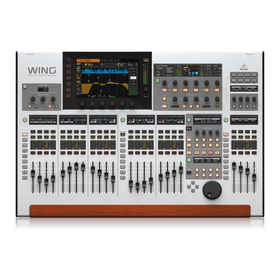
We have built upon the wildly-successful X32 platform to bring a product to the audio world that expands the capabilities and ease-of-use in every way. Continue through this guide to get a broad overview of the WING's functionality, and don't forget to visit behringer.com for tutorial videos and guides.
Before you start
The first shipments of the WING console are equipped with an early version of the firmware that will surely be outdated by the time it reaches customers. If you're reading this, you are one of the privileged few to get your hands on this console first and experience all the new benefits.
It is wise to periodically check for new firmware updates, as new features and bug fixes will be released regularly. Our development team is eager to react to customer suggestions as much as it is to surprise you with improvements and new features. Visit the product page on behringer.com to download the latest firmware so you can enjoy the full potential of your WING.
Please refer to Chapter 6 in this QSG for details about the update process.
Source and Channel – a new routing approach
WING takes the idea of labeling channels with names, icons and colors one step further to the actual Source. Combining and balancing the ratio between audio sources is the fundamental reason for mixing. It is not about the channel, where audio processing is applied, it is the Source that matters in the first place. Hence, WING Sources comprise a specific input, its preamp parameters like gain, mute and phantom power, the mode mono/stereo/mid-side, a name, icon and color, as well as user-definable tags.
These Sources can be used by one or several channels for applying processing and sending the audio to buses or mains. They can also be patched to any output directly when no processing is desired, such as recording setups or when sharing audio with another console for independent mixes.
To summarize:
Sources – This is technically any entry point of audio into the console. An input could be an analog XLR or ¼" connection to the rear panel, signals from a stage box, USB connection, expansion card, etc. These are the anchor points for any audio processing and routing in WING. The Source carries identifying characteristics like name, color, icon, and tags, and it also owns the gain, mute, phantom power and mono/stereo/mid-side mode of that input.
48 Mono/Stereo Input Channels – Every Input Channel can be connected to a Main and an Alternative Source. Channels in WING allow to apply extremely powerful and flexible processing to the Source audio. They can inherit the Source's customization properties like name, icon, color and tags. They will automatically use the input audio in mono or stereo depending on the Source's mode, and there is no need for linking channels to a stereo pair any longer. Channel audio can then be sent to buses or mains for mixing, or it can be tapped individually for connecting outputs directly.
16 Stereo Buses and 4 Stereo Mains – The 16 Buses will typically be used for send-style FX processing or monitor mixing, and will often be sent to one of the 4 Mains. Both Buses and Mains can be sent to Matrix, User Signals or Output destinations.
8 Matrix Buses – Matrix buses can be sent to User Signals or Output destinations, and are often used for sub or zone mixes.
Outputs - There are a huge number of analog and digital destinations, where processed, mixed or raw Source audio can be sent to—without any restrictions.
See Patching and Setup for more details and an example scenario.
Hardware Descriptions
VIEW buttons

Each major section of the console's top panel has a button called VIEW. Pressing one of these will switch the Main Display to a dedicated screen for the section whose VIEW button was pressed. The Main Display will often have additional parameters, options or information that is not accessible from the top panel alone.
While active, a VIEW button will light green. Pressing the same VIEW button will return the Main Display to the screen that was previously active, and the VIEW button will lose illumination. Manually navigating away from the screen that was selected with a VIEW button will also cause it to dim.
In some cases, pressing a VIEW button is just a shortcut to a screen that could otherwise be reached via Main Screen navigation, and in other cases it is the only way to access a screen.
Some VIEW buttons support a press-and-hold function that accesses an additional configuration page. For example, pressing and holding any of the fader bank VIEW buttons accesses the edit screen where channels and buses can be rearranged.
The VIEW button for the Channel Strip section to the right of the Main Display will act in conjunction with the 6 block buttons within that section (Input, Filter, Gate, etc). These merely act as shortcuts to pages within the Home screen, so very few common functions are more than a button press away.
Monitoring/Talkback/USB

A USB type-A connector allows a flash drive to be plugged directly into the console for saving or loading data. This allows you to always have a backup of your show files, or even use a rented WING console while retaining your usual setup. The connector also allows recording and playback of audio files. The port can charge a portable device such as a phone or tablet, which is especially convenient if you frequently rely on a device like this to mix wirelessly.
The section also has dedicated level knobs for the headphone outputs (located on the underside of the top edge) and the monitor outputs (which default to Aux output 7/8 on the rear panel). Engaging the DIM button reduces the monitor volume, and the MONO button sums the monitor signal to mono.
The talkback mic level can be adjusted via TALK LEVEL knob, and TALK A and B buttons send the talkback signal to different destinations. Either Channel 40 or Aux 8 can be used as input for the talkback channel.
Press the VIEW button to control the monitor settings, adjust the amount of Dim attenuation, select routing for the talkback mic, and other parameters.
Fader Sections

The WING has 3 fader sections that each have their own associated bank buttons. The group of 12 faders to the left side of the console are labeled mostly for input channels, the group of 8 faders in the center typically control buses and DCAs, and the small group of 4 faders to the right are meant for main or matrix outputs. However, there are no restrictions with how the fader banks can be configured. To access the fader bank configuration, press and hold the VIEW button for one of the fader sections.
Layer/Bank buttons

Selecting different fader banks will instantly bring a new set of channels to the associated fader section, including the scribble strip names/icons, and the motorized faders will jump to their correct positioning. If a particular bank does not fit on the available physical faders in a section (for example, Bus Masters), the shift arrows will scroll in blocks of 4 to access the remaining channels. Each fader section also has 2 user-defined banks that can contain a variety of channels.
For monitor mixing, a very convenient feature called Sends on Faders is available to quickly adjust the channel send levels to a particular bus.
- Press the SOF FLIP button to activate Sends on Faders. The MUTE buttons on all sends (input channel fader strips) are active by default to protect buses in subgroup mode.
- Make sure the BUS MASTERS button is lit in the bus fader section, then press one of the SELECT buttons to identify the bus to which channel signals will be sent.
- Raise the input channel faders for each of the channels that should be sent to that bus, navigating through the different input banks if necessary.
Remember to disengage the SOF FLIP button when you want to return to normal mixing.
Scribble strips, meters, select

Each fader strip has a mini display screen called a scribble strip. This will indicate information about the current channel/bus number, name and even a graphic icon to quickly identify which channel is currently controlled by the fader and associated buttons. A color bar above the scribble strip allows quick visual identification of groups of related channels. Scribble strip details and color bar options can be edited on the HOME screen/HOME tab by pressing the CUSTOMIZE button.
Pressing the SELECT button directs the control focus of the Main Display and Channel Strip section to that channel or bus. Only one SELECT button can be active at any time.
The SOLO button will isolate that channel for monitoring, along with any other channels or buses that are soloed. The MUTE button mutes the channel currently assigned to that strip.
Stereo level meters provide input level information at a glance, from -60 dB to Clip. The DYNAMICS LED will light whenever the dynamics threshold is exceeded, thus triggering the compressor/expander. Likewise, the GATE LED will light whenever the input signal falls below the noise gate threshold.
Main Display

The majority of the WING's controls can be edited and monitored via the 10" touch screen Main Display. Various screens can be accessed with the 7 buttons along the left side of the screen, as well as the VIEW buttons located in each major section of the top panel.
6 encoders along the bottom of the display allow parameter adjustments of the items shown at the bottom of the current display screen. These are capacitive knobs that will highlight elements on the screen as soon as the associated knob is touched.
An additional 7th encoder to the right of the display can be used for contextdependent control by first touching an item on the Main Display, allowing for finer adjustments compared to moving virtual knobs or faders. A multi-purpose button beneath the 7th encoder performs similarly depending on the current screen. For example, it can be used as a tap tempo when editing delay effects.
The large stereo meter will either display the main bus or solo bus levels. The CLR SOLO button will release all channels and buses that are active in the solo bus.

The navigation arrows and value/scrub wheel perform functions pertaining to DAW control as well as the USB Audio and WING-LIVE players. The wheel can also fine-tune values of parameters assigned in the User layer of the Custom Controls while respective buttons are depressed.
Channel Strip Section

The channel strip provides quick access to the primary parameters for the currently-selected channel. A display screen provides dedicated editing details for the parameter being adjusted, and various indications for input configuration, bus and group assignments, and metering are always visible for convenience.
One of 7 channel editing blocks (including EQ) can be sent to the editing display screen by pressing the associated button or touching the capacitive encoder knob directly above. Press and hold the button to turn the block on or off. Pressing the VIEW button will open the HOME screen of the selected channel on the Main Display.
Once a block is already active, pressing the block button again will scroll through several parameters for editing, and the associated encoder can be used for adjustments. Small dots in the lower right corner of the display indicate how many parameters can be scrolled through by repeatedly pressing the block button.
An additional EQ section has dedicated controls for adjustment of up to 6 EQ bands for input channels and 8 bands for buses. Engage the EQ block by pressing and holding the EQ button, then touch one of the 4 EQ encoder knobs to select a band for adjustment. Press the SHIFT button to access the low and hi shelf bands, and additional bands if editing a bus EQ.
The GAIN, WIDTH and FREQ buttons select which element of the current band will be adjusted with the encoder.
Press the LISTEN button in the lower right corner to monitor the EQ band in isolation. The BLEND/MIX knob acts as a wet/dry adjustment for the EQ block.
This can be used to exaggerate or de-emphasize the current EQ setting.
4-Channel Section

The edit section above the righthand fader bank offers a special set of dedicated control elements. This can be parameters like gain, pan, filters or effects sends for the selected bank of 4 channels.
Pressing one of the 8 buttons enables the 4 knobs and 4 buttons to control channel properties without actually selecting the channel for editing. This makes the 4-channel section independent from the main control surface, and would allow for a second audio engineer to work in parallel to the FOH engineer.
Custom Controls

The Custom Controls section allows up to 4 rotary knobs and 8 buttons to be configured for control of specific elements that should be available at all times regardless of the main display screen focus. A common use could be the vocal channel's reverb send level. Presets can also be configured to suit different sets, venues, operators, etc. Press the VIEW button to assign functions to the controls, optimize the scribble strips, or reset the controls.
Show/Mute/Transport/Automix Control

The bottom portion of the Custom Control section allows quick access to different categories. Press the VIEW button to configure each of them. It offers a combination of user-assignable buttons and pre-configured buttons for controlling the USB recorder, the WING LIVE recorder, Mute Groups and Show Control.
Rear Panel
Analog I/O

The rear panel analog connections include 8 MIDAS PRO series microphone preamps and 8 XLR outputs, plus 8 balanced ¼" aux input and output connectors. A lamp socket accepts a standard 12 V light. 5-pin MIDI IN and OUT jacks allow external MIDI control, and a pair of ¼" TRS jacks for GPIO allow basic input and output commands.
Power

Connect the included IEC cable.
AES50/Control/StageCONNECT

A pair of Ethernet ports allow a network to be set up via router for wired or wireless control using one of the control apps for PC, phone or tablet. A USB port allows bidirectional 48-channel transmission as well as firmware updates and data exchange. An ASIO driver can be behringer.com.
3 AES50 ports can each provide up to 48 input and output channels to and from digital stageboxes, ensuring abundant channel count and allowing patching from multiple locations. The WING is fully compatible with all X32 series mixers and stage boxes.
Cabling for all AES50 connections between WING and stage boxes:
- Shielded CAT-5e cable
- Ethercon terminated cable ends
- Maximum cable length of 80 meters
StageCONNECT is a proprietary connection for transmitting up to 32 audio channels via standard XLR and DMX cable. The interface supports different bus configurations of input and output channels and uses digital, uncompressed PCM at 44.1/48 kHz and 24-bit resolution. StageCONNECT was developed for flexible connections on stage using standard mic cable, supporting a wide range of stage boxes and monitoring systems at sub-millisecond latency.
Stereo AES/EBU input and output connections can be made via XLR cables.
Expansion Slot

The WING ships with the WING-LIVE card installed, which allows up to 64 channels of 48 kHz / 32-bit audio to be recorded onto a pair of SD or SDHC cards. Other options such as Dante, SoundGrid and MADI will be available for purchase as well.
Main Screens
Most of the advanced editing and control is done on the Main Display. Screens can be accessed via the 7 buttons to the left of the screen, or via VIEW buttons in each section of the top panel.
The layout varies greatly from screen to screen, but a fairly permanent status bar can be seen along the top of the screen to provide quick reference for channel name, clock, and alerts. This also allows constant access to the SD card controls, setup menu, library functions and other tools.
HOME
The HOME screen defaults to an overview of the selected channel. This screen allows adjustment of basic parameters like pan and level, but mostly provides a launch point to important processing blocks like EQ and dynamics. The blocks can be navigated using the left column regardless of which block is currently in view. Note that the processing sequence of gate, dynamics, EQ, and insert can be adjusted by pressing the Edit button at the bottom of the left column.
The INPUT screen appears second in the left-hand column, though the order of the blocks can be customized on the default/overview screen. The primary and alternate Source that is assigned to the current channel is selected here. The FILTER screen is also a part of this section, allowing low cut, hi cut and advanced filtering options like tilt filter and all-pass filter for phase alignment.
The GATE screen appears 3rd in the left-hand column, though the order of some blocks can be customized on the HOME overview screen. The block defaults to a simple noise gate with common parameters like threshold and ratio, though many other effects can be selected from the Gate Model menu. This block's name will change to reflect the chosen model.
The EQ block defaults to a 6-band fully-parametric equalizer for input channels, and 8-band for buses. A variety of EQ models can be selected from the EQ Model menu.
The DYNAMICS block offers a large selection of generic and legendary compressors, expanders and limiters.
Two INSERT blocks are available by default, one that can be positioned before or after the Gate, EQ and/or Dynamics blocks, and another that is fixed post-fader and input processing.
The MAIN screen allows the send level to each of the 4 Master buses to be adjusted along with the width, pan and level.
The last screen in the left-hand column allows adjustment of send levels to all 16 buses.
The Home screen has a similar appearance when a bus is selected, but no gate block is available and only trim can be adjusted. The bus mode can be set to pre or post-fader if they will be used for monitoring or effects, or subgroup if channels will be routed to the bus prior to the main mix.
EFFECTS
The EFFECTS screen controls all aspects of the 16 effects processors. Users can select from a large collection of effects, configure routing, adjust parameters and monitor levels.
Effects are usually applied to channels in one of two ways – Send-style effects, and Insert effects. Time-based effects like reverb and delay work well as Send effects, whereas modulation or compression effects tend to work better as Inserts so that they can process the entire signal.
Send effects are achieved by sending at least one, though often multiple channels to a bus that contains an effect such as reverb. Use one of the Insert points on the bus to select one of the many reverb effects. The channels are sent to the main output bus along with the bus that carries the effect signal. By varying the amount of signal sent to the effect bus, a proper blend of "dry" signal will appear in the main output along with the "wet" effect signal.
The channel HOME screen is already set up with a couple of Insert points, one of which can be patched at several points in the signal flow. Tap one of the INS blocks in the left-hand column to assign an effect processor. A chorus or flanger effect will probably sound better as an insert rather than a send, and whether the effect goes before or after the EQ and dynamics blocks is a matter of preference.
METERS
The METERS screen displays different groups of level meters for various signal paths, allowing quick analysis of any channels or buses that might need level adjustment.
ROUTING
The ROUTING screen allows patching and configuration of sources and outputs. Two icons at the top of the Main Display determine whether the page focuses on sources (inputs) or outputs.
Press the pull-down menu to select onboard analog connectors, AES50, USB, WING LIVE, etc. For Source groups, details such as name, color, icon, tags, and mono/stereo/mid-side mode can be configured here.
With outputs selected, the routing can be viewed for each analog or digital output destination. To assign new sources for outputs, first disable the lock function.
SETUP
The SETUP screen allows network configuration for remote control of the console with a PC, tablet or smartphone running one of the dedicated apps. The screen also allows various global settings and I/O configuration for expansion cards and GPIO. The date and time can also be set on this screen.
The current firmware version is listed in the bottom right corner, which can be updated either via the rear panel USB port, or via a flash drive connected to the top panel port. See the Chapter 6 for details.
LIBRARY
The LIBRARY screen allows the current console state to be saved into Snapshots for later recall. The scope of parameters that are recalled can be specified prior to loading. Global Safes further protect certain areas of the console from being affected by snapshot recall. See Chapter 5 for details.
UTILITY
This button does not have its own screen, but rather works in conjunction with other screens. The function is context relative, so depending on which screen is currently active, pressing the UTILITY button may bring up additional preset options or settings configuration.
Additional VIEW-based screens:
INPUT/BUS/MAIN – Pressing the VIEW button in any of the 3 fader sections will bring up an overview screen to monitor all input, bus or output channels at once.
MONITOR – Even though the top panel Monitor section has some hardware controls, a significant amount of configuration is available via the VIEW button to determine where Talkback paths are heard, monitor A and B sources, monitor bus EQ and metering, dimming levels, and more.
CHANNEL STRIP – The VIEW button in the Channel Strip will call up a screen relevant to the block that is currently being edited. All of the screens that are accessed with the Channel Strip VIEW button are also accessible via the Main Display HOME button, but provide more immediate access.
CUSTOM CONTROLS – The top and bottom portions of the Custom Control section each have their own VIEW button to edit the functions that are controlled by the hardware elements.
Patching and Setup
To help understand the basics of patching and signal flow, here is an example scenario that might be common for a live music event. In this hookup, the audio sources on stage are connected to an S16 stage box which sends the signals via shielded ethernet cable to the WING's AES50-A port. The physical connections to the stage box are a bit disorganized, but this can be repatched in the console in a more standardized way.
| S16 Input Physical | Connection | Source | Channel Assignment |
| 1 | Bass guitar DI | AES-A 1 | 7 |
| 2 | Lead guitar | AES-A 2 | 8 |
| 3 | Keyboard L | AES-A 3/L (linked) | 10 (stereo) |
| 4 | Keyboard L | AES-A 4/R | 10 (automatic) |
| 5 | Backing track L | AES-A 5/L (linked) | 11 (stereo) |
| 6 | Backing track R | AES-A 6/R | 11 (automatic) |
| 7 | Vocal stage R | AES-A 7 | 12 |
| 8 | Kick drum | AES-A 8 | 1 |
| 9 | Tom 1 | AES-A 9 | 2 |
| 10 | Tom 2 | AES-A 10 | 3 |
| 11 | Tom 3 | AES-A 11 | 4 |
| 12 | Snare | AES-A 12 | 5 |
| 13 | Overhead 1 | AES-A 13/L (linked) | 6 (stereo) |
| 14 | Overhead 2 | AES-A 14/R | 6 (automatic) |
| 15 | Vocal stage L | AES-A 15 | 13 |
| 16 | Acoustic DI | AES-A 16 | 9 |
The Source is what gives meaning and identity to an input, which makes patching WING Sources to channels very evident and clear.
Press the ROUTING button and touch the pull-down menu at the top of the screen. Select 'AES50 A' from the list of input groups. Press the 'A 1' square, which will allow the Source details to be defined, including the name, icon, color, phantom power, and even preliminary gain adjustment. If a pair of Sources should be linked as stereo or mid-side, this can be done as well. Note that the odd-numbered Source will always occupy the left side, and the even-numbered Source direct above it will occupy the right. Be sure to arrange your physical connections accordingly.
Press the HOME button on the Main Display and then the SELECT button for channel 1 in the first fader bank. If no Source is selected, no gain adjustment can be made. Press 'INPUT' on the HOME screen, or navigate to the second tab in the left-hand column. Press the Source Select square under the MAIN section and select AES50 A from the pull-down menu. Tap 'A 8' in the grid to assign the kick drum to channel 1.
Without leaving this page, press the SELECT button for channel 2 in the first fader bank. Select AES50 A-9 to assign Tom 1 to channel 2. Continue through the other channels to assign the otherwise messy physical connections at the stage box in a logical and organized manner. When assigning the overhead mics to channel 6, pressing AES 13/L will automatically route both mic signals to channel 6 in stereo.
On the ROUTING screen, press the output icon at the top of the screen. Touch the Output Group pull-down menu and select 'AES50 A'. Press the first square in the grid. Touch the Input Group pull-down menu and select BUS. Select 1L to assign bus 1 to XLR output 1 on the S16. Repeat this process for any other bus sends back to the stage. When editing output 7 and 8, select MAIN from the Input Group menu, then assign 1L to output 7 and 1R to output 8. These outputs will be connected to your power amplifiers or active main speakers.
Note – when using mono stage wedges, use the Mono button in the input section to set width to 0.
Presets and Snapshots Library
After putting in the effort to adjust the routing, channel processing and global preferences, it is highly recommended that a Snapshot be created to preserve the console state. This can be done in the Library section. Many options exist to select both the way that these are saved, as well as how the console state is protected when loading previously-saved Snapshots. The left-hand pane of the Snapshot Library will show a list of your Snapshots that have been saved to the main directory, as well as any folders that you have created to organize similar Snapshots. If many Snapshots are likely to be saved, or if multiple engineers will be using the console, then it may be more efficient to make good use of folders.
Recall Scope
Various elements of the console, including routing, channel processing, and global configuration can be selected or omitted both when saving and recalling a saved Snapshot. Channels, buses and FX engines will expand for easier select/deselect. Adjusting the recall scope prior to saving can act as a reminder to the purpose for that Snapshot being saved in the first place. When a saved Snapshot is selected from the library list, the state of the recall scope at the time the Snapshot was saved will be displayed. This also allows the scope to be further adjusted before loading. When the Snapshot is loaded, only the elements highlighted in blue will be affected.
Global Safes
Touch the GLOBAL SAFES button at the top of the screen to access these options. Certain elements can be protected from ever being affected by Snapshot recall.
To summarize:
Blue – channel/routing/config will be recalled when a saved Snapshot is loaded.
Grey – Specific element will not be recalled when a saved Snapshot is loaded.
Red – Highlighted element will never be affected by Snapshots because a Safe is active.
Transferring Libraries to a PC
- Library of Snapshots and Presets is stored in the internal DATA file system of your WING. This file system can be made available to connected personal computers for transferring, copying and exchanging data.
- Open the SETUP/Global Settings Edit page and enable DATA ACCESS.
- Connect a USB cable to the rear panel port and to your computer.
- A virtual drive will appear on your computer, similar to connecting a flash drive or external hard drive. Double click the drive to open.
- Any stored Snapshots and Presets will show up and can be copied to the PC.
Firmware Updates
The WING console firmware can be easily updated via USB. Download the firmware file from the product page on Behringer.com and follow these steps.
- Open the Setup/Global Edit page and enable OS ACCESS.
- Connect a USB cable to the rear panel port and to your computer.
- A virtual drive will appear on your computer, similar to connecting a flash drive or external hard drive. Double click the drive to open.
- Drag the new firmware file into the drive.
Note, although WING will always boot using the most recent firmware in that drive, it is recommended to delete older firmware files or move them to a subfolder. If the console does not boot up normally, you can still update the firmware using this procedure:
- With console powered off, connect a USB cable to the rear panel port and to your computer.
- Press and hold the Select button next to the Main Display, then power the console on.
- An OS and DATA drive will appear on your computer, similar to connecting a flash drive or external hard drive. Double click a drive to open.
- Drag the new firmware file into the OS drive.
- Note, WING will always boot using the most recent firmware in that drive.
- After the file has transferred, eject the virtual drive. The console should reboot automatically with the new firmware installed. If it doesn't, power cycle the console manually.
Initialize to Default Settings
You can reset the console to its initial state if you need to ensure that no previous settings are interfering with what you plan to set up from scratch. There are two ways to achieve this:
> by opening the Setup/Global Edit page and selecting INIT CONSOLE.
> by pressing and holding the CLEAR SOLO button on the Main Display while powering the console up.
Specifications
| Processing | |
| Input processing channels | 40 stereo input channels, 8 stereo aux channels |
| Output processing channels | 16 stereo aux buses, 8 stereo matrices, 4 stereo mains |
| Internal effects engines (all true stereo) | 8 premium FX, 8 standard FX |
| Point-to-point routing matrix | 500 x 502 signals |
| Signal processing | 40-bit floating point, 48 kHz |
| A/D converters (8-channel, 192 kHz-ready, 24-bit) | 114 dB dynamic range* |
| D/A converters (stereo, 192 kHz-ready, 24-bit) | 120 dB dyanmic range* |
| I/O latency (console input to output) | 1.0 ms |
| Network latency (stage box in > console > stage box out) | 1.2 ms |
| Connectors | |
| MIDAS PRO series microphone preamplifier (XLR) | 8 |
| XLR balanced outputs | 8 |
| Aux inputs/outputs (1/4" TRS balanced, mono) | 8 in / 6 out + 2 monitor / phones outs |
| Phones output (1/4" TRS, stereo) | 2 |
| Digital AES/EBU input/output (XLR) | 1 / 1 |
| AES50 ports (KLARK TEKNIK SuperMAC, 100 Mbit/s) | 3 |
| Expansion card interface | 64 x 64 channel audio input / output |
| StageCONNECT master I/O (12 V / 18 W power supplied, XLR, 32 channels) | 1 |
| MIDI inputs/outputs | 1 / 1 |
| GPIO on TRS, configurable | 2 x 2 |
| USB 2.0 type B device (48 x 48 ch 24-bit audio and MIDI I/O) | 1 |
| USB 2.0 type A host (audio and data, 5 VDC, 1 A) | 1 |
| Ethernet LAN ports, RJ45, 1 Gbit/s | 2, internally switched |
| Audio over IP (AoIP) internal module socket (Dante, AES67 or SoundGrid modules optional) | Up to 64 x 64 channels @ 48 kHz |
| IEC mains socket with power switch | 1 |
| Mic Input Characteristics (Mic Input to Analog Output) | |
| Design | MIDAS PRO series |
| THD+N (0 dB gain, 0 dBu output) | <0.004%* |
| THD+N (+40 dB gain, 0 dBu to +20 dBu output) | <0.006%* |
| Input impedance (unbalanced / balanced) | 1 kΩ / 2 kΩ |
| Non-clip maximum input level | +21 dBu |
| Phantom power (switchable per input) | +48 V |
| Equivalent input noise @ +45 dB gain (150 Ω source) | -128 dBu* |
| CMRR @ unity gain (typical) | >50 dB |
| CMRR @ 40 dB gain (typical) | >70 dB |
| Input/Output Characteristics | |
| Frequency response @ 48 kHz sample rate, 0 to -1 dB (any gain setting) | 10 Hz - 20 kHz |
| Dynamic range, analog in to analog out (typical), XLR / aux | 111 dB* / 108 dB* |
| A/D dynamic range, preamplifier and converter (typical), XLR / aux | 112 dB* / 110 dB* |
| D/A dynamic range, converter and output (typical), XLR / aux | 118 dB* / 112 dB* |
| Crosstalk rejection @ 1 kHz, adjacent channels | 100 dB |
| Output level, XLR connectors (nominal / maximum) | +4 dBu / +21 dBu |
| Output impedance, XLR connectors (unbalanced / balanced) | 75 Ω / 75 Ω |
| Input impedance, TRS connectors (unbalanced / balanced) | 20 kΩ / 40 kΩ |
| Non-clip maximum input level, TRS connectors | +16 dBu |
| Aux output level, TRS (nominal / maximum) | +4 dBu / +16 dBu |
| Aux output impedance, TRS (unbalanced / balanced) | 150 Ω / 300 Ω |
| Phones output impedance / maximum output level | 500 mW @ 75 Ω / +18 dBu |
| Residual noise level, XLR out 1-16 connectors, unity gain | -97 dBu* |
| Residual noise level, aux and monitor TRS out connectors | -95 dBu* |
| Displays | |
| Main screen | 10.1" TFT LCD, 1280 x 800 px, capacitive touch |
| Main screen swivel, continuous adjustment | 15°- 60° |
| 4-channel group LCD screen with RGB color strip per channel | 320 x 48 monochrome |
| Channel editing screen | 2.4" TFT LCD, 320 x 240 px |
| Main stereo meter | 18 segment (-60 dB to clip) |
| Controls | |
| 100 mm motor faders | 12 + 8 + 4 |
| Touch-sensitive rotary controls | 3 + 7 + 11 + 4 + 4 |
| Custom controls | |
| Fully assignable rotary controls | 4 |
| Fully assignable backlit buttons | 8 + 8 |
| Variable rotary controls / buttons | 4 / 4 |
| Power | |
| Switch-mode power supply | Auto-ranging 100-240 VAC (50/60 Hz) |
| Power consumption | 130 W |
| Physical | |
| Standard operating temperatur range | 5°C – 40°C (41°F – 104°F) |
| Dimensions (HxWxD) | 201 x 870 x 575 mm (7.9 x 34.3 x 22.6") |
| Weight | 24 kg (52.8 lbs) |
*A-weighted noise and dynamic range figures
LEGAL DISCLAIMER
Music Tribe accepts no liability for any loss which may be suffered by any person who relies either wholly or in part upon any description, photograph, or statement contained herein. Technical specifications, appearances and other information are subject to change without notice. All trademarks are the property of their respective owners. Midas, Klark Teknik, Lab Gruppen, Lake, Tannoy, Turbosound, TC Electronic, TC Helicon, Behringer, Bugera, Auratone and Coolaudio are trademarks or registered trademarks of Music Tribe Global Brands Ltd.
© Music Tribe Global Brands Ltd. 2019 All rights reserved.
LIMITED WARRANTY
For the applicable warranty terms and conditions and additional information regarding Music Tribe' s Limited Warranty, please see complete details online at musictribe.com/warranty.
Zhongshan Eurotec Electronics Limited
No. 10 Wanmei Road, South China Modern Chinese Medicine Park, Nanlang Town, 528451, Zhongshan City, Guangdong Province, China

Documents / Resources
References
Download manual
Here you can download full pdf version of manual, it may contain additional safety instructions, warranty information, FCC rules, etc.
Download Behringer WING - Digital Mixing Console Quick Start Guide
Advertisement
Thank you! Your question has been received!


Need Assistance?
Do you have a question about the WING that isn't answered in the manual? Leave your question here.