Table of Contents
Advertisement
Quick Links
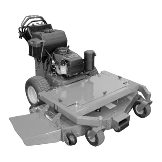
Pro Unit
Owner/Operator Manual
Models
988105 - HR1536FX
988106 - HR1548FX
988107 - HR1548FL
988108 - HE1748FL
988109 - HE1752FL
988113 - HR1544FX
988116 - HR1548FLP
988117 - HE1752FLP
988120 - HR1536FXP
988314 - HR1536FXPCE
ENGLISH
FRANÇAIS
ESPAÑOL
Supersedes 04941500, A
04941500B 12/03
Printed in USA
Advertisement
Table of Contents

Related Manuals for Ariens GRAVELY Pro Unit HR1536FX


Summary of Contents for Ariens GRAVELY Pro Unit HR1536FX
- Page 1 Pro Unit Owner/Operator Manual Models 988105 - HR1536FX 988106 - HR1548FX 988107 - HR1548FL 988108 - HE1748FL 988109 - HE1752FL 988113 - HR1544FX 988116 - HR1548FLP 988117 - HE1752FLP 988120 - HR1536FXP 988314 - HR1536FXPCE ENGLISH FRANÇAIS ESPAÑOL 04941500B 12/03 Supersedes 04941500, A Printed in USA...
- Page 2 Facsimile (920) 756-2407 DECLARAÇÃO DE CONFORMIDADE CE EMITIDA PELO FABRICANTE – We the undersigned, ARIENS COMPANY, certify that: Nous, soussignés ARIENS COMPANY, certifions que : Der Unterzeichnete, ARIENS COMPANY, bescheinigt, dass: Wij, de ondergetekenden, ARIENS COMPANY, verklaren dat: Undertegnede, ARIENS COMPANY, attesterer, at: La sottoscritta società...
- Page 3 Philip J. Smucker: 11/24/2003 Quality and Conformance Manager (Keeper of Technical File) Date Date Datum Ariens Company Responsable de la qualité et de la conformité des produits Datum Dato Data (Dépositaire de la fiche technique) Manager Qualitätssicherung Fecha Dato Datum Brillion, WI 54110-0157 USA und Konformität (Archivar der technischen Akte) Kwaliteits- en...
-
Page 4: Table Of Contents
2. Check the safety interlock system to make sure that it is functioning properly. (See Check Safety Interlock System on page 10.) 3. Fill out Original Purchaser Registration Card and return the card to Gravely. 4. Explain Limited Warranty Policy. © Copyright 2003 Ariens Company GB-4... -
Page 5: Safety
5. Explain recommended lubrication and maintenance. 6. Instruct customer on controls and operation of unit. Advise customer on adjustments. Discuss and emphasize the Safety Precautions. Give customer Owner/Operator, Parts, and Engine Manuals. Advise customer to thoroughly read and understand them. SAFETY NOTATIONS WARNING: This cutting machine is capable... - Page 6 Always stand clear of discharge area. DO NOT direct discharge toward other people. Remove objects that could be thrown by the blade. DO NOT operate mower over gravel and hard OL0910 surfaces. Keep people and pets away when operating unit. Keep children out of the work area and under the watchful care of a responsible adult.
- Page 7 ALWAYS be aware of traffic when operating along streets or Thrown objects can cause injury and property damage. DO curbs. NOT point discharge at anyone or discharge directly onto paved or gravel surfaces. Keep children and people away. Always stand clear of the discharge area when operating Keep children out of work area and under watchful care of a this unit.
- Page 8 DO NOT operate in reverse unless absolutely necessary. Reverse connections may result in sparks which can cause ALWAYS backup slowly. ALWAYS look down and behind, serious injury. Always connect positive (+) lead of charger to before and while backing. positive (+) terminal, and negative (-) lead to negative (-) terminal.
-
Page 9: Assembly
Use only attachments or accessories designed for your unit Use extra care with grass catchers and other attachments. and that can be used safely on your terrain. These can change the stability of the unit. Use only approved hitch points. Check attachment components frequently for wear, damage or deterioration. -
Page 10: Operation
OPERATION 988116, 117, 120, 314 WARNING: AVOID INJURY. Read and To test: understand the entire Safety section before 1. With engine off, set controls as listed in line A of the proceeding. table below and try to start the engine. IMPORTANT: If the system does not function properly, do CONTROLS AND FEATURES not operate the unit until repairs are made. - Page 11 Operator Presence Control (988105, 106, 107, 108, Ignition Switch (988108, 109, 117) 109, 113) Operate the ignition switch with the removable The operator presence control lever must be depressed to key. The switch has three positions: Off (1), On operate the PTO. When the speed control levers are in (2) and Start (3).
- Page 12 PTO Clutch (988116, 117, 120, 314) WARNING: AVOID INJURY. Lock steering control levers in neutral before disengaging cold start feature. Unit will move if steering controls are engaged when cold start feature is released. Notch OE0261 Pull the PTO (power take off) switch past On (1) to Reset (2) to engage the mower blades.
- Page 13 STARTING AND SHUT OFF 4. Move PTO switch to Off. 5. If the engine is cold, choke the engine. Before Each Use 6. Move the throttle to Fast. Check each item in Each Use in the Maintenance Schedule. 7. Put the ignition key in the switch and turn it to Start. NOTE: The engine will not start unless the speed control IMPORTANT: DO NOT operate starter motor more than 15 levers are in neutral, the parking brake is On and the Power...
- Page 14 988105, 106, 107, 108, 109, 113 • To move in reverse, pull both steering levers up, past the neutral position. Pulling the levers farther up To operate: increases reverse speed. 1. Start the engine (See Starting and Shut Off on page 13).
- Page 15 • To move straight forward, slowly push control levers IMPORTANT: NEVER engage the PTO if the mower is forward. plugged with grass or other material. This will damage the PTO belt. 4. Push control levers forward slowly. When you know how to operate the unit, select a speed appropriate to your mowing conditions.
- Page 16 988116, 117, 120, 314 Floating Deck Cutting Heights 1. Shut off the unit. See Shut Off on page 13 and "To stop mowing." (25) 2. Remove the key. (38) 3. Lock pivot bar against control levers. (51) 4. Chock or block the wheels if parked on a slope. (64) TO PUSH UNIT BY HAND (76)
-
Page 17: Maintenance Schedule
MAINTENANCE SCHEDULE Period Service Task Check Safety Interlock System WARNING: Safety interlock system failure and improper operation of unit can result in death or serious injury. Test this system each time the unit is operated. If this system does not function as described, do not operate until repairs are made. -
Page 18: Service And Adjustments
SERVICE AND ADJUSTMENTS 2. Remove tank from frame and allow tank to tip rearward WARNING: AVOID INJURY. Read and to allow oil to drain from system (Figure 8). understand the entire Safety section before 3. After most of the oil has drained, turn the tank upside proceeding. - Page 19 GENERAL LUBRICATION 5. Adjust tracking if needed. Try each of the following steps until the unit tracks straight. It Apply a small amount of oil to the pivot points as required for may not be necessary to perform all the steps. smooth operation (Figure 9).
- Page 20 1. Parking Brake Rod 2. Clevis 3. Parking Brake Arm Figure 14 SPEED CONTROL NEUTRAL ADJUSTMENT (988105, 106, 107, 108, 109, 113, 116, 117, 120) 1. Reverse Stop Bolt 2. Neutral Adjustment Bracket Check Neutral Figure 11 1. Put speed control levers in neutral. 2.
- Page 21 2. Remove steering link clevis from steering control rod. 3. Turn the clevis down the steering link rod lengthen the link. 4. Replace clevis on steering control rod. 5. Check for backwards creep. 6. If unit creeps backwards, adjust steering rod clevis (see Speed Control Neutral Adjustment).
- Page 22 Slower Speed 1. Clevis Connect clevis 2. Speed Control here for faster Plate speed range. 3. Pump Actuating Spring 4. Pump Actuating Spring Anchor Faster Speed 1. Neutral Bracket 2. Clevis 3. Speed Control Arm Figure 18 Figure 17 OG1340 REMOVE SINGLE LEVER PLATE (988105, 106, 988116, 117, 120, 314 107, 108, 109, 113)
- Page 23 1. Armature 3. Inspection Slot 2. Rotor 4. Gap Adjustment OG0795 Figure 20 1. Mower Clutch 4. Hydro Pump Belt OG1500 Sheave 5. Pump Pulleys 2. Mower Belt BATTERY (988108, 109, 117) 3. Pump Belt Idler Unit comes equipped with a maintenance-free battery that Spring requires no regular maintenance except cleaning the Figure 19...
- Page 24 • Internal Contact: Drink large quantities of water. 5. Make the final jumper cable connection to the engine Follow with Milk of Magnesia, beaten egg or vegetable block or the furthest ground point away from the oil. Get medical attention immediately! DO NOT induce discharged battery.
- Page 25 4. Remove mower drive belt idler spring (Figure 23). DO NOT sharpen to this pattern 5. Remove mower drive belt from deck sheaves and mower clutch sheave. 6. Install new mower drive belt on deck sheaves and mower clutch sheave. 7.
-
Page 26: Storage
Sharpen the Mower Blades 2. Sharpen mower blade by removing an equal amount of material from each end of mower blade. DO NOT Figure 24. change angle of cutting edge or round the corner of the mower blade. CAUTION: DO NOT sharpen mower blades while on unit. -
Page 27: Accessories
PROBLEM PROBABLE CAUSE CORRECTION Changes in the 1. Loose or missing fasteners. 1. Check all the fasteners. Replace if necessary. sound or 2. Mower blade problem. 2. Check blades for wear or damage. See Mower vibrations of the Blades on page 25. unit 3. -
Page 28: Specifications
SPECIFICATIONS Model Number 988105 988106 988107 988108 988109 Description HR1536FX HR1548FX HR1548FL HE1748FL HE1752FL Length – in. (cm) 79.75 (202.50) 73.5 (186.70) 77 (195.60) Height – in. (cm) 42 (106.7) Width – in. (cm) 38.2 (97) 50.6 (128.5) 52.4 (133.1) Actual Weight –... - Page 29 SPECIFICATIONS Model Number 988113 988116 988117 988120 988314 Description HR1544FX HR1548FLP HE1752FLP HR1536FXP HR1536FXPCE Length – in. (cm) 75.5 (191.77) 77.5 (196.78) 84.25 (214.0) Height – in. (cm) 42 (106.7) 43.5 (110.5) Width – in. (cm) 47 (119.38) 50.6 (128.5) 52.4 (133.1) 38.2 (97) Actual Weight –...
-
Page 30: Warranty
2-Year Limited Warranty Gravely Division of Ariens Company (Gravely) hereby warrants to the original consumer purchaser that all Gravely Two-Wheel, Gravely Division of Ariens Company Professional G, Pro, and ProMaster products will be free from defects 655 West Ryan Street in material and workmanship for a period of two (2) years from the date P.O. - Page 31 GRAVELY A Division of Ariens Company 655 West Ryan Street P.O. Box 157 Brillion, WI 54110-0157 920-756-2141 Fax 920-756-2407 www.gravely.com WARNING The engine exhaust from this product contains chemicals known to the State of California to cause cancer, birth defects or other reproductive harm.