Sony DSC-W130 Service Manual
Hide thumbs
Also See for DSC-W130:
- Instruction manual (182 pages) ,
- Manual pratique (140 pages) ,
- Handbook (128 pages)
Table of Contents
Advertisement
Quick Links
SERVICE MANUAL
Ver. 1.0 2008.01
Revision History
Revision History
Internal memory
Internal memory
ON BOARD
ON BOARD
Link
Link
SPECIFICATIONS
SERVICE NOTE
DISASSEMBLY
• Precaution on Replacing the SY-190 Board
The components identified by
mark 0 or dotted line with
mark 0 are critical for safety.
Replace only with part num-
ber specified.
DSC-W130_L2
9-852-263-31
BLOCK DIAGRAMS
FRAME SCHEMATIC DIAGRAM
SCHEMATIC DIAGRAMS
Les composants identifiés par une
marque 0 sont critiques pour la
sécurité.
Ne les remplacer que par une pièce
portant le numéro spécifié.
Sony EMCS Co.
DSC-W130
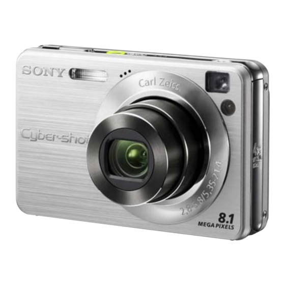
Photo: Silver
DIGITAL STILL CAMERA
LEVEL
US Model
Canadian Model
AEP Model
UK Model
E Model
Hong Kong Model
Chinese Model
Korea Model
Argentine Model
Brazilian Model
PRINTED WIRING BOARDS
REPAIR PARTS LIST
Published by Kohda TEC
2
2008A0500-1
© 2008.1
Advertisement
Table of Contents

Related Manuals for Sony DSC-W130


Summary of Contents for Sony DSC-W130
- Page 1 0 are critical for safety. sécurité. Replace only with part num- Ne les remplacer que par une pièce ber specified. portant le numéro spécifié. DIGITAL STILL CAMERA 2008A0500-1 DSC-W130_L2 © 2008.1 Sony EMCS Co. 9-852-263-31 Published by Kohda TEC...
-
Page 2: Specifications
SPECIFICATIONS [Input and Output connectors] Camera BC-CSGB/BC-CSGC battery charger Multi connector: Video output [System] Audio output (Monaural) Power requirements: AC 100 V to 240 V, Image device: USB communication 50/60 Hz, 2 W (BC-CSGC)/ 7.18 mm (1/2.5 type) color CCD, Primary USB communication: Hi-Speed USB (USB 2.0 2.6 W (BC-CSGB) color filter... -
Page 3: Safety Check-Out
CRITIQUES POUR LA SÉCURITÉ DE FONCTIONNEMENT. NE COMPONENTS WITH SONY PARTS WHOSE PART NUMBERS REMPLACER CES COMPOSANTS QUE PAR DES PIÈSES SONY APPEAR AS SHOWN IN THIS MANUAL OR IN SUPPLEMENTS DONT LES NUMÉROS SONT DONNÉS DANS CE MANUEL OU PUBLISHED BY SONY. -
Page 4: Self-Diagnosis Function
1. SERVICE NOTE 1-1. PRECAUTION ON REPLACING THE SY-190 BOARD DESTINATION DATA When you replace to the repairing board, the written destination data of repairing board also might be changed to original setting. Refer to Service Manual ADJ, and perform “DESTINATION DATA WRITE”. USB SERIAL No. -
Page 5: Process After Fixing Flash Error
1-2-3. Self-diagnosis Code Table Self-diagnosis Code Block Detailed Symptom/State Correction Function Code The internal memory has experienced a Format the internal memory. format error. “Memory Stick Duo” is unformatted. Format the “Memory Stick Duo”. “Memory Stick Duo” is broken. Insert a new “Memory Stick Duo”. “Memory Stick Duo”... -
Page 6: Method For Copying Or Erasing The Data In Internal Memory
1-4. METHOD FOR COPYING OR ERASING THE DATA IN INTERNAL MEMORY The data can be copied/erased by the operations on the HOME screen. (When erasing the data, execute formatting the internal memory.) Note 1: When replacing the SY-190 board, erase the data in internal memory of the board before replacement. Note 2: When replacing the SY-190 board, execute formatting and initialize the internal memory after replacement. -
Page 7: How To Write Data To Internal Memory
To change the setting, use the write enable tool “WriteEnableTool.exe”. Data writing method Connect the PC to the camera (USB mode: Mass Storage), and switch the driver to the “Sony Seus USB Driver”. Start the Write Enable Tool and the SeusEX. -
Page 8: Note For Repair
2. DISASSEMBLY NOTE FOR REPAIR • Make sure that the flat cable and flexible board are not cracked of bent at the terminal. Cut and remove the part of gilt Do not insert the cable insufficiently nor crookedly. which comes off at the point. (Be careful or some •... -
Page 9: Identifying Parts
2-1. IDENTIFYING PARTS Cabinet (Rear) Cabinet (Upper) ⋅ AF-112 Board ⋅ ST-180 Board BT Holder Section ⋅ MC-189 Flexible Board ⋅ ST-188 Flexible Board ⋅ SY-190 Board LCD Frame ⋅ SW-520 Board ⋅ SW-533 Flexible Board Cabinet (Front) Lens Block ⋅... -
Page 10: Lcd Section
HELP HELP 2-2. DISASSEMBLY EXPLODED VIEW HARDWARE LIST 2-2-1. LCD SECTION Follow the disassembly in the numerical order given. 1 Cabinet (Rear) (1-1 to 1-5) 2 LCD (2-1 to 2-17) 1 Cabinet (Rear) 1-4 (Boss) HELP 1 1-1 (#20) 2-16 1-3 (#20) 2-15 (Solder) -
Page 11: Front Section
2-2-2. FRONT SECTION EXPLODED VIEW HARDWARE LIST Follow the disassembly in the numerical order given. 1 Cabinet (Front) (1-1 to 1-3) 2 Lens Block (2-1 to 2-6) HELP 4 BT Holder Section (See Page 2-5) 1 Cabinet (Front) HELP 4 1-3 (Claw) 2-1 (#20) 1-1 (Claw) - Page 12 2-2-3. BT HOLDER SECTION EXPLODED VIEW HARDWARE LIST Follow the disassembly in the numerical order given. 1 Cabinet (Upper) Block (1-1 to 1-4) 2 SY-190 Board (2-1 to 2-5) 2SY-190 Board 1 Cabinet (Upper) Block HELP 6 2-1 (#3) (Solder) 2-2 (Claw) HELP 5 1-3 (Claw)
-
Page 13: Precautions When Holding The Lens Block
2-3. PRECAUTIONS WHEN HOLDING THE LENS BLOCK • Hold the Lens Block at the center of both sides. Hold here. • Do not hold the following part. Lens Flexible Board Lens Barrel Lens Barrier ∗Very weak Optical Stepping Motor Zoom Motor ∗Very weak Focus Lens OVF Cam Plate... -
Page 14: Barrier Assy Replacing Method
2-4. BARRIER ASSY REPLACING METHOD Removal 1 Turn on the power switch and extend the lens. 2 Detach the battery. 3 Pour a solvent such as alcohol from two places A to the tweezers or a needle shown below into a gap of Ornamental Ring A. 4 Remove while turning the Ornamental Ring A right and left. -
Page 15: Lens Motor Replacing Method
2-5. LENS MOTOR REPLACING METHOD Replace the parts if the following events appear when the power switch is turned on. 1 "Turn off and on the power" is displayed without performing the zoom operation. Replace Zoom Gear Block if a damage of lens barrel due to a drop of camera is not found. (See "2-5-1. - Page 16 2-5-2. Optical Stepping Motor Replacing Method Removal 1 Disengage the lens flexible board from the claw. 2 Disconnect the connector of the lens flexible board. 3 Remove Zoom Gear Block by referring to the removal 1 to 3 in "2-5-1. Zoom Gear Block Replacing Method". 4 Remove three screws.
- Page 17 Installation 1 Install the lens flexible board with four solders. 2 Referring to the following figure, check each part state of lens rear block. 3 Install Optical Stepping Motor. 4 Tighten one screw. * Tightening torque = 0.049 ± 0.01N • m (0.5 ± 0.1kgf • cm) 2 ...
- Page 18 2-5-3. FINAL INSPECTION (NO FAULT IN ACTUAL MOTION/ACTUAL SCREEN) 1 Zoom motion (Check five postures: horizontal, upward/downward, upper/lower oblique 45º) No abnormal sound or motion must be found over full stroke between TELE end and WIDE end. 2 Zoom image No abnormality such as a skipped image or wavy image must be found in the image through LCD or finder over full stroke between TELE end and WIDE end.
- Page 19 HELP Sheet attachment positions and procedures of processing the flexible boards/harnesses are shown. HELP 1: HELP 3: LCD Window Adhesive Sheet Kit LCD Insulating Sheet LCD Window Adhesive Sheet Kit must use only - Front Side - the part of LCD window edge. LCD Insulating Sheet Please discard other parts.
- Page 20 HELP 4: HELP 5: Tape (AF)/Capacitor Protection Sheet BT Terminal Harness BT Holder Tape (AF) BT902 (White) BT903 (Black) BT901 (Red) Tape (AF) SY-190 Board BT Terminal Harness BT Holder Mold Capacitor Protection Sheet DSC-W130_L2 HELP...
- Page 21 HELP 6: Sheets and Harness of ST-180 Board - Top View - Harness (HN-062) (Gray) ST Insulating Sheet Harness (HN-061) (Yellow) ST-180 Board Harness (HN-059) (Pink) Harness (HN-060) (Blue) When connecting the harness to the strobe capacitor terminals, wind the naked leads of the harness around the terminals by more than Mic Harness (Orange) 1.5 turns, and then solder them.
- Page 22 HELP 7: Installation Method of Battery Terminal Board 1 Insert the battery terminal board into a slit in the BT holder to install. * The battery terminal board is attached with the notch for installation. BT holder Notch Battery terminal Battery terminal board board 2 Fold the notch 3 or 4 times repeatedly to break.
- Page 23 HELP 8: Lens Flexible Board/CD-718 Flexible Board CD-718 Flexible Board Apply the fold trace. Lens Flexible Board Apply the fold trace. HELP 9: MC-189 Flexible Board Apply the fold trace. MC-189 Flexible Board DSC-W130_L2 HELP...
-
Page 24: Overall Block Diagram
3. BLOCK DIAGRAMS Link Link OVERALL BLOCK DIAGRAM (1/2) POWER BLOCK DIAGRAM (1/2) OVERALL BLOCK DIAGRAM (2/2) POWER BLOCK DIAGRAM (2/2) DSC-W130_L2... - Page 25 3. BLOCK DIAGRAMS 3-1. OVERALL BLOCK DIAGRAM (1/2) ( ) : Number in parenthesis ( ) indicates the division number of schematic diagram where the component is located. LENS BLOCK CD-718 FLEXIBLE BOARD SY-190 BOARD (1/2) LCD901 (1/2) LCD MODULE CN301 LENS IRIS...
- Page 26 3-2. OVERALL BLOCK DIAGRAM (2/2) ( ) : Number in parenthesis ( ) indicates the division number of schematic diagram where the component is located. SY-190 BOARD (2/2) MC-189 FLEXIBLE CN709(2/2) BOARD (2/2) XPWR_ON XPOWER_ON XPOWER_ON ACV_UNREG ACV_UNREG ST_UNREG MS_VCC EVER CAM_13V CAM_3.5V...
- Page 27 3-3. POWER BLOCK DIAGRAM (1/2) ( ) : Number in parenthesis ( ) indicates the division number of schematic diagram where the component is located. MC-189 SY-190 BOARD (1/2) FLEXIBLE F001 BOARD CN709 F002 ACV_UNREG ACV_UNREG IC001 Q001, Q002 DC/DC CONVERTER (9/10) XACV_DET XACV_DET CN001...
- Page 28 3-4. POWER BLOCK DIAGRAM (2/2) ( ) : Number in parenthesis ( ) indicates the division number of schematic diagram where the component is located. LCD901 LCD MODULE SY-190 BOARD (2/2) CN704 L702 M_5.0V VDDD2IN L701 D_3.1V VDD1A 2.5INCH VDD1D COLOR IC507 XDD_SYS_RST...
- Page 29 4. PRINTED WIRING BOARDS AND SCHEMATIC DIAGRAMS 4-1. FRAME SCHEMATIC DIAGRAM LENS BLOCK SW-520 BOARD CD-718 FLEXIBLE BOARD ST-188 FLEXIBLE BOARD SW-533 FLEXIBLE BOARD IC003 (Not supplied) BT901 BT902 BT903 BATTERY − TERMINAL BT900 ST-180 BOARD (SIDE B) LITHIUM BATTERY LCD901 LCD MODULE CN002...
-
Page 30: Schematic Diagrams
4-2. SCHEMATIC DIAGRAMS Link Link SW-520 BOARD CD-718 FLEXIBLE BOARD (CCD IMAGER) (CONTROL SWITCH) MC-189 FLEXIBLE BOARD ST-180 BOARD (1/2) (FLASH DRIVE) (MULIT CONNECTOR) ST-188 FLEXIBLE BOARD ST-180 BOARD (2/2) (CONTROL SWITCH) (SY-ST CONNECTION) SW-533 FLEXIBLE BOARD AF-112 BOARD (AF ILLUMINATOR) (SY-SW CONNECTION) COMMON NOTE FOR SCHEMATIC DIAGRAMS DSC-W130_L2... -
Page 31: This Note Is Common For Schematic Diagrams
4-2. SCHEMATIC DIAGRAMS 4-2. SCHEMATIC DIAGRAMS 4-2. SCHEMATIC DIAGRAMS THIS NOTE IS COMMON FOR SCHEMATIC DIAGRAMS (In addition to this, the necessary note is printed in each block) (For schematic diagrams) 1. Connection • All capacitors are in µF unless otherwise noted. pF : µ Pattern box µF. - Page 32 CAM_-7.5V_CD C005 0.1u VHLD2 VHLD2 VHLD1 VHLD1 IC003 ICX636EQP-13 Note: IC003 (CCD imager) and CD-718 flexible complete board are 8M CCD IMAGER LND001 not supplied, but there are included in CCD block assy. VST2 VST2 LND002 Note: Voltages of IC003 can not be measured, VST1 VST1 DGND...
- Page 33 Schematic diagrams of the SY-190 board are not shown. Pages from 4-4 to 4-13 are not shown. DSC-W130_L2...
- Page 34 • Refer to page 4-2 for mark 0. AF-112 LND033 LND201, LND202 Through the XAF_LED Harness (HN-061, HN-062) D_3.1V Page 4-15 CN002 of Level 2 LND034 L001 ST_UNREG 2.2uH ST_UNREG ST_UNREG D001 R005 LND038 C006 4700 CRF02(TE85R) 220p C002 22u C REG_GND LND035 6.3V...
- Page 35 • Refer to page 4-2 for mark 0. Note: LCD901 is not included in SW-520 complete board. LCD901(2/2) LCD MODULE LND001 XAE_LOCK_LED D101 BL_H (AE/AF LOCK) CL-196SYG-CD-T KEY_AD1 BL_L XSTRB_LED KEY_AD2 BACKLIGHT LND002 D102 REG_GND LNJ426W830S0 (FLASH CHARGE/RECORD) MODE_DIAL1 MODE_DIAL2 S003 S008 XPWR_LED...
- Page 36 LND001 REG_GND LND002 AU_LINE_OUT LND003 A_GND LND004 V_LINE_OUT LND005 V_GND Note: CN001 (multi connector) is not supplied, but this is included in MC-189 flexible complete board. LND006 HD_Y LND007 XACC_IN LND008 ACV_UNREG LND009 ACV_UNREG LND010 ACV_UNREG LND011 ACV_UNREG LND012 ACV_UNREG LND013 ACV_UNREG LND014...
- Page 37 LND031 ST_UNREG ST_UNREG LND041 LND042 ST_UNREG ST_UNREG LND030 LND043 ST_UNREG ST_UNREG LND029 LND044 LND028 LND045 REG_GND REG_GND LND027 REG_GND REG_GND LND046 LND026 REG_GND REG_GND LND047 LND025 LND048 STRB_CHG STRB_CHG LND024 STRB_ON STRB_ON LND049 LND023 LND050 ST_5V ST_5V LND022 LND051 STRB_CHG_CONT STRB_CHG_CONT LND021 XSTRB_FULL...
-
Page 38: Printed Wiring Boards
4-3. PRINTED WIRING BOARDS Link Link CD-718 FLEXIBLE BOARD SW-520 BOARD ST-180 BOARD MC-189 FLEXIBLE BOARD AF-112 BOARD COMMON NOTE FOR PRINTED WIRING BOARDS DSC-W130_L2... -
Page 39: This Note Is Common For Printed Wiring Boards
4-3. PRINTED WIRING BOARDS 4-3. PRINTED WIRING BOARDS 4-3. PRINTED WIRING BOARDS THIS NOTE IS COMMON FOR PRINTED WIRING BOARDS • : Uses unleaded solder. • Chip parts. • : Circuit board Transistor Diode : Flexible board Pattern from the side which enables seeing. : pattern of the rear side (The other layers’... - Page 40 CD-718 (2 layers) : Uses unleaded solder. CD-718 FLEXIBLE BOARD LND001 LND002 LND003 LND004 LND005 LND006 LND007 LND008 LND009 LND010 LND011 LND012 LND013 LND014 LND015 LND016 LND017 LND018 LND019 LND020 LND021 C C C C C C C C C C C C C C C C C C LND022...
- Page 41 Printed wiring board of the SY-190 board is not shown. Page 4-20 is not shown. DSC-W130_L2...
- Page 42 ST-180 (4 layers), AF-112 (2 layers) : Uses unleaded solder. MIC901 MICROPHONE BLOCK ST-180 BOARD (SIDE A) (SHUTTER) POWER S101 LND101 S102 D003 C008 D103 LND102 C006 (POWER) LND037 IC001 R005 HARNESS (HN-060) (Blue) C901 CL002 C001 CHARGING C003 D101 L001 C002 CAPACITOR...
- Page 43 SW-520 (2 layers) : Uses unleaded solder. SW-520 BOARD (SIDE B) SW-520 BOARD (SIDE A) S003 S008 (ZOOM) BL-H LND001 TO LCD901 (BACKLIGHT) S010 BL-L LND002 (MODE DIAL) VDR001 Note: S010 (Mode dial) is not supplied, but this is included in SW-520 complete board. S010 MENU HOME...
- Page 44 MC-189 (2 layers) : Uses unleaded solder. MC-189 FLEXIBLE BOARD (MULTI CONNECTOR) CN001 Note: CN001 (multi connector) is not supplied, but this is included in MC-189 flexible complete board. R004 LF001 1-874-415- DSC-W130_L2 MC-189 4-23E...
-
Page 45: Repair Parts List
NOTE NOTE 5. REPAIR PARTS LIST NOTE: Characters A to Z of the electrical parts list indicate location of exploded views in which the desired part is shown. EXPLODED VIEWS EXPLODED VIEWS Link Link LCD SECTION FRONT SECTION BT HOLDER SECTION CABINET (UPPER) SECTION LENS SECTION ELECTRICAL PARTS LIST... - Page 46 5. REPAIR PARTS LIST 5. REPAIR PARTS LIST 5. REPAIR PARTS LIST NOTE: • -XX, -X mean standardized parts, so they may have some differences from When indicating parts by reference number, the original one. please include the board name. •...
-
Page 47: Hardware List
5. REPAIR PARTS LIST 5. REPAIR PARTS LIST DISASSEMBLY HARDWARE LIST 5-1. EXPLODED VIEWS 5-1-1. LCD SECTION ns: not supplied (Note) LCD901 #118 Front Section (See page 5-3) Note: Refer to “HELP 1: LCD Window Adhesive Sheet Kit” when replace the LCD window adhesive sheet kit. Ref. - Page 48 5. REPAIR PARTS LIST 5. REPAIR PARTS LIST DISASSEMBLY HARDWARE LIST 5-1-2. FRONT SECTION BT Holder Section (See page 5-4) (including IC003 (CCD imager) and CD-718 flexible complete board) (Note 1, 2) Lens Section (See page 5-6) Note 1: Be sure to read “Precuations for Replacement of Imager”...
- Page 49 5. REPAIR PARTS LIST 5. REPAIR PARTS LIST DISASSEMBLY HARDWARE LIST 5-1-3. BT HOLDER SECTION ns: not supplied SILVER BT903 (Note) BT902 (Note) 106 107 Cabinet (Upper) Section (See page 5-5) BT901 (Note) Note: Refer to “HELP 7: Installation method of battery terminal board” when changing the battery terminal board.
-
Page 50: Cabinet (Upper) Section
5. REPAIR PARTS LIST 5. REPAIR PARTS LIST HARDWARE LIST 5-1-4. CABINET (UPPER) SECTION ns: not supplied SP901 MIC901 (Note) C901 (Note) BT900 : BT900 (LITHIUM RECHARGEABLE BATTERY) Board on the mount position. (See page 4-21) Note: Refer to “HELP 6: Sheets and Harness of ST-180 Board” when replace harness (HN-059/060). -
Page 51: Lens Section
5. REPAIR PARTS LIST 5. REPAIR PARTS LIST HARDWARE LIST 5-1-5. LENS SECTION ns: not supplied (Note 4) (Note 1) (Note 4) (Note 3) (Note 2) (Note 4) (Note 2) (Note 3) (Note 2) (Note 3) (Note 3) Note 1: Refer to “2-3. Precuations when Holding the Lens Block”... - Page 52 AF-112 CD-718 MC-189 ST-180 5-2. ELECTRICAL PARTS LIST Ref. No. Part No. Description Ref. No. Part No. Description A-1494-317-A AF-112 BOARD, COMPLETE < CONNECTOR > ********************** * CN002 1-817-391-81 CONNECTOR, FPC (ZIF) 31P < DIODE > < DIODE > * D201 6-501-861-01 DIODE CL-360S-TD4-X-TL (SELF-TIMER/SMILE SHUTTER/AF ILLUMINATOR) 0 D001...
- Page 53 SW-520 Ref. No. Part No. Description Ref. No. Part No. Description A-1494-316-A SW-520 BOARD, COMPLETE *********************** (S010 (Mode dial) is not supplied, but this is included in SW-520 complete board.) < CONNECTOR > * CN001 1-820-634-51 CONNECTOR, FPC (LIF (NON-ZIF)) <...
- Page 54 Checking supplied accessories. Note: This item is supplied with the unit as an accessory, but is not prepared as a service part. Battery Charger Battery Charger Instruction Manual 3-286-605-11 (ENGLISH) (CND, AEP, UK, E, HK) BC-CSGB/BC-CSGC BC-CSGB/BC-CSGC 0 1-480-175-21 (US, CND) 0 1-480-175-31 3-286-605-21 (FRENCH, ITALIAN) (CND, AEP) (EXCEPT US, CND)
- Page 55 HARDWARE LIST (1/7) #1: M1.7 X 2.5 #2: M1.7 X 4.0 #3: M1.7 X 2.5 #4: M1.4 X 2.5 (Tapping) (Black) (Black) (Red) (Dark Silver) 2-635-562-11 2-635-562-31 2-660-401-01 3-348-998-81 #5: M1.7 X 3.5 (Tapping) #6: M1.4 X 1.7 #7: M1.7 X 1.6 #8: M1.7 X 3.5 (Tapping) (Black) (Silver)
- Page 56 HARDWARE LIST (2/7) #21: M1.4 X 3.0 #22: M1.7 X 5.0 (Tapping) #23: M1.7 X 4.0 (Tapping) #24: B1.7 X 5.5 (Tapping) (Black) (Silver) (Black) (Black) 2-662-396-21 3-083-261-01 3-080-204-11 4-679-805-11 #25: M1.7 X 3.0 #26: M1.4 X 2.0 #27: M1.4 X 2.0 #28: M1.4 X 4.0 (Tapping) (Black) (Silver)
- Page 57 HARDWARE LIST (3/7) #41: M3.0 X 8.0 (Tapping) #42: M2.0 X 4.0 (Tapping) #43: M1.7 X 4.0 #44: M1.7 X 3.0 (Tapping) (Silver) (Silver) (Red) (Silver) 3-065-748-01 7-628-253-00 2-660-401-31 3-078-890-61 #45: M1.4 X 2.5 #46: M1.7 X 3.0 #47: M1.4 X 3.0 (Tapping) #48: M1.7 X 2.5 (Silver) (Red)
- Page 58 HARDWARE LIST (4/7) #64: M1.7 X 5.0 (Tapping) #61: M3.0 X 10.0 #62: M2.0 X 3.0 #63: M5.0 X 12.5 (Silver) (Black) (Silver) (Black) 2-666-551-21 7-682-549-09 3-080-202-21 3-060-811-21 12.5 10.0 #65: M1.4 X 3.5 #66: M1.4 X 1.4 #67: M1.4 X 2.0 #68: M1.7 X 4.0 (Silver) (Silver)
- Page 59 HARDWARE LIST (5/7) #81: M1.7 X 2.5 #82: M1.4 X 1.4 #83: M1.7 X 7.0 (Tapping) #84: M2.0 X 3.0 (Silver) (Silver) (Black) (Silver) 2-515-756-01 3-272-251-01 3-080-204-41 3-072-453-11 #85: M1.7 X 2.5 #86: M1.7 X 4.0 (Tapping) #87: M1.6 X 5.3 #88: M1.6 X 5.9 (Tapping) (Black) (Silver)
- Page 60 HARDWARE LIST (6/7) #101: M2.0 X 5.0 #102: M2.6 X 8.0 #103: M2.6 X 10.0 #104: M3.0 X 8.0 (Silver) (Black) (Silver) (Black) 7-621-555-39 7-621-284-30 7-685-794-09 7-682-548-09 10.0 #105: M2.0 X 4.0 #106: M2.0 X 6.0 #107: M2.0 X 5.0 #108: M1.7 X 3.0 (Tapping) (Red) (Black)
- Page 61 HARDWARE LIST (7/7) #121: M2.0 X 4.0 (Tapping) #122: M3.0 X 6.0 #123: M4.0 X 8.0 #124: M1.7 X 2.0 (Silver) (Black) (Black) (Silver) 3-080-205-11 7-682-547-09 7-682-561-09 2-599-475-01...
- Page 62 Reverse 985226331.pdf Revision History S.M. Rev. Ver. Date History Contents issued 2008.01 Official Release — — DSC-W130_L2...