
Summary of Contents for neno LEADX Ultra
- Page 1 NENO LEADX Ultra Manual NENO LEADX Ultra Assembly instructions, operating instructions and safety V1.2 © NENO-CNC Schweiz 2023 Seite | 1...
-
Page 2: Table Of Contents
NENO LEADX Ultra Manual Index General ..............................6 About the NENO LEADX Ultra ......................6 Limitation ............................7 Safety ............................... 8 Responsibility of the operator ......................8 Personal protective device ........................8 Safety ............................... 9 Ambient conditions ..........................9 Residual risk ............................9 Required tools ............................ - Page 3 NENO LEADX Ultra Manual 2.6 Aligning ............................28 2.6.1 Tightening the ball nut adapter plate ..................28 2.6.2 Fixed bearings ........................... 29 2.6.3 Stepper motor .......................... 30 2.6.4 Loose bearing ........................... 31 2.6.5 Retaining ring ........................... 32 2.7 Axis complete ..........................33 2.7.1 Completed Y-axis ........................
- Page 4 NENO LEADX Ultra Manual 3.4.3 - End caps ..........................55 3.5 Substructure complete ........................56 4.0 X-axis..............................57 4.1 C-beam and HGR rail ........................57 4.1.1 HGR rail preparation ......................... 57 4.1.2 Attaching the HGR rails to the C-Beam profile ................. 58 4.1.3 Alignment Tool .........................
- Page 5 NENO LEADX Ultra Manual 5.1.2 Attaching the MGN rail to the C-Beam ..................83 5.1.3 Alignment Tool ......................... 84 5.1.4 MGN 15 Bulkheads ........................85 5.2 Z-plate .............................. 86 5.3 Ball screw ............................87 5.3.1 Ball nut and spherical nut plate ....................87 5.3.2 Ball nut plate and Z-plate ......................
-
Page 6: General
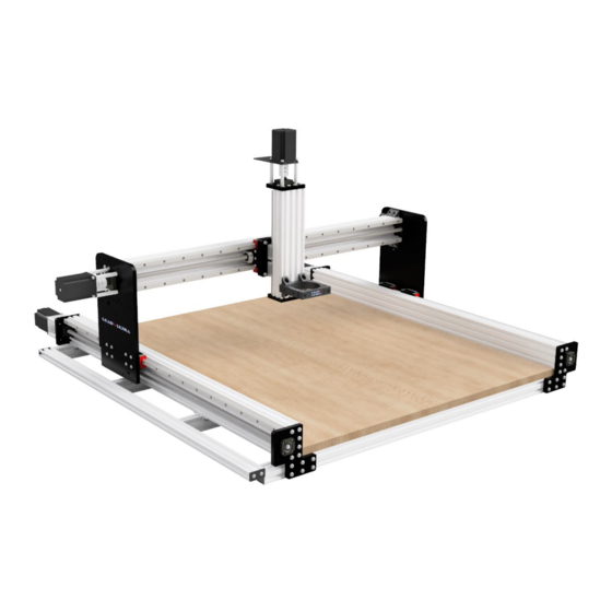
After the success of our simple but stable LEADX Pro, we were increasingly confronted with inquiries about more complex and stable milling machines. The LEADX Ultra is based on the same aluminium profiles as the LEADX Pro, but dispenses with the roller system and the trapezoidal threaded spindles and uses high-precision linear guides and ball screws. -
Page 7: Limitation
The obligations agreed in the delivery contract, the general terms and conditions as well as the terms of delivery of the manufacturer NENO-CNC and the legal regulations valid at the time of conclusion of the contract apply. Furthermore, the statutory warranty provisions apply. -
Page 8: Safety
NENO LEADX Ultra Manual Safety Responsibility of the operator The operator of the NENO LEADX Ultra is responsible for the following points: The safety instructions have been read and understood. The construction was carried out completely according to instructions. The CNC milling machine has been properly tested before each operation and is only put into operation in perfect condition. -
Page 9: Safety
NENO LEADX Ultra Manual Safety Ambient conditions Carry out the construction and operation of the milling machine only on a solid, flat surface. It should stand securely and not be able to slip. Make sure there is enough space around the machine so that you can work comfortably and the machine can fully extend its travels. -
Page 10: Required Tools
NENO LEADX Ultra Manual Required tools We recommend a set of tools needed to assemble the NENO LEADX Ultra. Of course, You can also use complementary tools. Allen key set Wrench or Ratchet Set Various screwdrivers Possibly M5 thread cutter for recutting... -
Page 11: Explanation Of The Basics
NENO LEADX Ultra Manual 1.0 Explanation of the basics 1.0.1 Machine axes Before we start, we start with the basic structure of a milling machine for reasons of understanding. On the picture we can see the different axes that a classic portal milling machine has. The X-Portal runs on the two Y-axes. -
Page 12: Guidance
NENO LEADX Ultra Manual 1.0.2 Guidance For better orientation, it is important to know how the CNC milling machine is aligned. Front: The Z-axis is mounted on this side. Rear: The stepper motors of the Y-axes are installed on this side. -
Page 13: Cleaning Before Assembly
NENO LEADX Ultra Manual 1.1 Cleaning before assembly It is recommended to degrease guide rails and block carriages before assembly. The grease, which is located on the guide rails and block carriages when preserved, is called bearing grease. This grease is intended to prevent rusting of the guides during storage and shipping. -
Page 14: Y-Axis
NENO LEADX Ultra Manual 2.0 Y-axis It is recommended to read and understand all steps between 2.1 and 2.7 before starting assembly. The t-slot nuts must be inserted into the channel of the aluminium profile for later steps, and if they are missing, the steps must be dismantled again. -
Page 15: Hgr Rail Preparation
NENO LEADX Ultra Manual 2.1.1 HGR rail preparation Number of screws for Y-axis length Article Nr. Description 1000MM 1500MM M4 x 14mm cylinder head bolt with hexagon socket M4 sliding T-nut HGR 15 rail Insert the M4 x 14mm cylinder head screw through the HGR rail and screw the M4 sliding nut to the other end. -
Page 16: Attaching The Hgr Rail To The C-Beam
NENO LEADX Ultra Manual 2.1.2 Attaching the HGR rail to the C-beam Article Nr. Description Quantity C-Beam Profile HGR 15 rail Slide the HGR 15 rail assembly into the upper channel of the C-Beam profile as shown in the drawing. -
Page 17: Alignment Tool
NENO LEADX Ultra Manual 2.1.3 Alignment tool Article Nr. Description Quantity Alignment tool HGR 15 rail Slide the alignment tool onto the HGR 15 rail and bring it close to the end of the rail. Tighten the M4 x 14 mm screw pre-assembled in chapter 2.1.1 n. -
Page 18: Hgh Storage Blocks
NENO LEADX Ultra Manual 2.1.4 HGH storage blocks Article Nr. Description Quantity HGH 15 bearing blocks HGR 15 rail Slide the 2x HGH 15 bearing blocks onto the HGR 15 rail. To avoid the loss of bearing balls, store the supplied plastic holder on the bearing block. When mounting the bearing block on the rail, use the rail to push the plastic bracket out of the block so that the steel balls are preloaded and in contact with a rail at all times. -
Page 19: Insertion Of T-Nuts
NENO LEADX Ultra Manual 2.1.5 Insertion of T-nuts Number of screws for Y-axis length Article Nr. Description 1000MM 1500MM M5 sliding T-nut C-Beam Profile Slide M5 T-nuts into the two lower channels on the 40 mm front side of the C-beam profile, as shown. -
Page 20: Y-Plate
NENO LEADX Ultra Manual 2.2 Y-plate 2.2.1 Y-plate and bearing block Article Nr. Description Quantity HGH 15 bearing blocks Precision washer M4 M4 x 16mm screw with flat head Y-plate left Insert the M4x 16mm flat head bolts through the M4 precision washer and Y-plate on the left and screw them onto the HGH bearing blocks as shown in the figure. -
Page 21: Ball Screw
NENO LEADX Ultra Manual 2.3 Ball screw 2.3.1 Ball nut and ball nut plate Article Nr. Description Quantity M4 x 20mm screw with flat head Ballscrew-nut Ball-nut adapter plate Ball screw 1210 Place the ball nut adapter plate on the ball screw. -
Page 22: Ball Nut Plate And Y-Plate
NENO LEADX Ultra Manual 2.3.2 Ball nut plate and Y-plate Article Nr. Description Quantity M4 x 20mm screw with flat head Ball nut adapter latte Gasket 50 x 10mm Y-plate left Tighten the ball nut adapter plate on the left Y-plate with 3 x M4x 20 mm lens screws. Insert the gasket 50x10mm between the ball nut plate/bracket and the Y-plate on the left. -
Page 23: End Plates
NENO LEADX Ultra Manual 2.4 End plates 2.4.1 End plate (fixed end) Article Nr. Description Quantity C-Beam M5 x 20mm flat head screw Y-End Plate - Fixed End Precision washer 10x5x1 Ball screw 1210 Insert 6x M5 x 20mm hexagon socket screws through the precision washer 10x5x1. Attach the Y-End Plate - Fixed End to the C-Beam with the screws. -
Page 24: End Plate (Loose End)
NENO LEADX Ultra Manual 2.4.2 End plate (loose end) Article Nr. Description Quantity C-Beam Y-end plate - loose end Precision washer 10x5x1 Ball screw 1210 M5 x 20mm flat head screw Insert 6x M5 x 20mm hexagon socket screws through the precision disc 10x5x1. -
Page 25: Fk And Ff Camps
NENO LEADX Ultra Manual 2.5 FK and FF camps 2.5.1 FF bearings (loose bearings) Article Nr. Description Quantity Y-end plate - loose end FF bearing block (loose bearing) M3 x 12 mm flat head screw Pass the FF bearing block (loose bearing) through the ball screw. -
Page 26: Fk Warehouse (Fixed Bearings)
NENO LEADX Ultra Manual 2.5.2 FK warehouse (fixed bearings) Article Nr. Description Quantity Y-End Plate - Fixed End FK bearing block (fixed bearing) M4 x 16 mm flat head screw Pass the FK bearing block (fixed bearing) through the ball screw. -
Page 27: Locking Nut And Diaphragm Coupling
NENO LEADX Ultra Manual 2.5.3 Locking nut and diaphragm coupling Article Description Quantity FK storage block (fixed bearing) FK locking nut Manually screw the FK lock nut onto the end of the ball screw, which is located at the fixed end. -
Page 28: Aligning
NENO LEADX Ultra Manual 2.6 Aligning 2.6.1 Tightening the ball nut adapter plate Article Nr. Description Quantity Ball nut y-assembly Tighten the screws on the ball nut plate/bracket as shown in the figure. Avoid tightening too tightly. The seal has a minimum of flexibility to compensate for misalignment of the system. -
Page 29: Fixed Bearings
NENO LEADX Ultra Manual 2.6.2 Fixed bearings Article Nr. Description Quantity M4 x 16mm screw with flat head (pre- assembled) Slide the Y-plate to the left toward the fixed end of the actuator, as shown in the figure below. Bring the Y-plate as close as possible to the fixed storage and then tighten the 4x M4x 16mm lens screws. -
Page 30: Stepper Motor
NENO LEADX Ultra Manual 2.6.3 Stepper motor Article Nr. Description Quantity Y-End Plate - Fixed End Precision spacers - 60mm Stepper motor M5 x 75mm cylinder head bolt First, insert the M5 x 75 mm cylinder head bolts through the mounting holes of the stepper motor and also through the 60 mm precision spacers, and then attach them to the Y-end plate - fixed end after aligning the motor shaft inside the diaphragm coupling. -
Page 31: Loose Bearing
NENO LEADX Ultra Manual 2.6.4 Loose bearing Article Nr. Description Quantity M3 x 12 mm flat head screw (pre- assembled) Slide the Y-plate to the right toward the loose end of the actuator as shown. Bring the Y-plate as close as possible to the loose bearing, then tighten the 4x M3x12 mm lens screws. -
Page 32: Retaining Ring
NENO LEADX Ultra Manual 2.6.5 Retaining ring Article Nr. Description Quantity Y-End Plate - Fixed End Retaining ring Place the retaining ring on the loose end of the ball screw with a retaining ring pliers as shown. © NENO-CNC Schweiz 2023... -
Page 33: Axis Complete
NENO LEADX Ultra Manual 2.7 Axis complete 2.7.1 Completed Y-axis Repeat this chapter to assemble the other Y-axis. You should have two Y-axes that are exactly mirrored to each other. 2x (mirrored) © NENO-CNC Schweiz 2023 Seite | 33... -
Page 34: Completed Y1 And Y2 Axes
NENO LEADX Ultra Manual 2.7.2 Completed Y1 and Y2 axes © NENO-CNC Schweiz 2023 Seite | 34... -
Page 35: Lubrication Of The Y1 And Y2 Axes
NENO LEADX Ultra Manual 2.8 Lubrication of the Y1 and Y2 axes 2.8.1 HGH bearing blocks Place the axles on the side and locate the grease nipple an the HGH bearing blocks. As we have already recommended, the grease nipples should be directed outwards. Connect the grease gun to the grease nipple and press the grease in. -
Page 36: Substructure
NENO LEADX Ultra Manual 3.0 Substructure It is recommended to read all chapters 3.1-3.5 before starting the assembly. 3.1 T-nuts 3.1.1 Insertion of T-nuts - front and rear profile Article Nr. Description Quantity M5 sliding T-nut 2040 Profile Slide the M5 sliding T-nuts into the 2040 profile as shown. 6 in each channel of one side on the wide side. -
Page 37: Mounting Brackets - Front And Rear Profile
NENO LEADX Ultra Manual 3.1.2 Mounting brackets - front and rear profile Article Nr. Description Quantity 2040 Profile M5 sliding T nut L2 angle bracket M5 x 8mm flat head screw On the side where we inserted 4x M5 slot stones in the previous step, attach the L2 bracket with 2x M5 x 8mm flat head screws. -
Page 38: Insertion Of T-Nuts - Middle Sections
NENO LEADX Ultra Manual 3.1.3 Insertion of T-nuts - middle sections Article Nr. Description Quantity M5 sliding T nut 2040 Profile Slide 4x M5 sliding T-nuts into each side of the upper channels of the wide side, as shown. The number of middle parts depends on the size of the machine you have. -
Page 39: Mounting Brackets - Middle Sections
NENO LEADX Ultra Manual 3.1.4 Mounting brackets - middle sections Article Nr. Description Quantity 2040 Profile M5 sliding T nut L2 angle bracket M5 x 8mm flat head screw On the side where we used 4x M5 T-nuts in the previous step, attach the L2 brackets with 2x M5 x 8 flat head bolts on each side of the 2040 profile. -
Page 40: Preparation Of The Substructure Completed
NENO LEADX Ultra Manual 3.1.5 Preparation of the substructure completed. Note that the fixed side is on the right; these brackets are all flush with the end of the profile and fully tightened. The brackets on the left side are still movable and will later be positioned and tightened according to the X-axis mounting. -
Page 41: Substructure Fixed Side
NENO LEADX Ultra Manual 3.2 Substructure fixed side 3.2.1 - Attach the Y2 axle to the reference side. Number of screws for Y- axis length Article Nr. Description 1000MM 1500MM 2040 profiles - front and back 2040 profiles - middle sections Y 2-axis Position the Y2 axis on the fixed side of your substructure, as shown in the figure below. -
Page 42: Attachment Of The Front (Loose End)
NENO LEADX Ultra Manual 3.2.2 - Attachment of the front (loose end) Article Nr. Description Quantity M5 x 8mm flat head screw L2 angle bracket Slide the sliding nut previously inserted into the lower channels of the C-beam of the Y2 axis towards the loose end, then use it to attach the M5 x 8mm flat head screws that secure the L2 brackets. -
Page 43: Attachment Of The Middle Sections To The Y2 Axis
NENO LEADX Ultra Manual 3.2.3 - Attachment of the middle sections to the Y2 axis. Article Nr. Description Quantity M5 x 8mm flat head screw L2 angle bracket Slide the previously inserted T-nuts of the C-beam of the Y2 axis to the correct places and attach the L2 angle brackets of the middle sections with the M5 x 8 mm lens screws. -
Page 44: Attachment Of The Back (Fixed End)
NENO LEADX Ultra Manual 3.2.4 - Attachment of the back (fixed end) Article Nr. Description Quantity M5 x 8mm flat head screw L2 angle bracket Slide the T-nut previously inserted into the lower channels of the Y-axis C-beam towards the fixed end, then use it to fasten the profile using the M5 x 8mm flat head screws. -
Page 45: Attachment Of The Rear Profile To The Y-End Plate (Fixed End)
NENO LEADX Ultra Manual 3.2.5 - Attachment of the rear profile to the Y-end plate (fixed end) Article Nr. Description Quantity Precision washer 10x5x1 M5 x 16mm flat head screw Use the T-nuts inserted into the 2040 profile in chapter 3.1.1 to attach the Y-end plate - firmly to the 2040 profile (rear). -
Page 46: Attachment Of The Front To The Y-End Plate (Loose End)
NENO LEADX Ultra Manual 3.2.6 - Attachment of the front to the Y-end plate (loose end) Article Nr. Description Quantity Precision washer 10x5x1 M5 x 16mm flat head screw Use the T-nuts inserted into the 2040 profile in chapter 3.1.1 to attach the Y-end plate – loose end to the 2040 profile (front). -
Page 47: Substructure - Loose Side
NENO LEADX Ultra Manual 3.3 Substructure – loose side 3.3.1 - Place the second Y-axis on the sliding side. QUANTITY FOR MACHINE Y-AXIS LENGTH Article Nr. Description 1000MM 1500MM 2040 profiles - front and back 2040 Profile - middle sections -axis Position the y-axis on the sliding side of the substructure, as shown in the figure below. -
Page 48: Attachment Of The Front (Loose End)
NENO LEADX Ultra Manual 3.3.2 - Attachment of the front (loose end) Article Nr. Description Quantity M5 x 8mm flat head screw L2 angle bracket Slide the T-nuts previously inserted into the lower channels of the C-beam of the Y1 axis towards the loose end, then use it to attach the M5 x 8mm flat head screws that secure the L2 angle bracket. -
Page 49: Attachment Of The Middle Sections To The Y-Axis
NENO LEADX Ultra Manual 3.3.3 - Attachment of the middle sections to the Y-axis. Article Nr. Description Quantity M5 x 8mm flat head screw L2 angle bracket Slide the previously inserted T-nuts of the C-beam of the Y1 axis to the correct locations and attach the L2 angle brackets of the middle sections with the M5 x 8 mm flat head screws. -
Page 50: Attachment Of The Back (Fixed End)
NENO LEADX Ultra Manual 3.3.4 - Attachment of the back (fixed end) Article Nr. Description Quantity M5 x 8mm flat head screw L2 angle bracket Slide the T-nuts previously inserted into the lower channels of the Y-axis C-beam towards the fixed end, then use it to fasten the profile using the M5 x 8mm flat head screws. -
Page 51: Attachment Of The Rear Profile To The Y-End Plate (Fixed End)
NENO LEADX Ultra Manual 3.3.5 - Attachment of the rear profile to the Y-end plate (fixed end) Article Nr. Description Quantity Precision washer 10x5x1 M5 x 16mm flat head screw Use the T-nuts inserted into the 2040 profile in chapter 3.1.1 to attach the Y-end plate – fixed end to the 2040 profile (rear). -
Page 52: Attachment Of The Front To The Y-End Plate (Loose End)
NENO LEADX Ultra Manual 3.3.6 - Attachment of the front to the Y-end plate (loose end) Article Nr. Description Quantity Precision washer 10x5x1 M5 x 16mm flat head screw Use the T-nuts inserted into the 2040 profile in chapter 3.1.1 to attach the Y-end plate – loose end to the 2040 profile (front). -
Page 53: Drag Chain Support
NENO LEADX Ultra Manual 3.4 - Drag chain support 3.4.1 - Attachment of the profile Article Nr. Description Quantity 2060 Profile M5 sliding T nut 90-degree angle bracket M5 x 8mm flat head screw Slide an M5 sT-nut into the channel of the 2060 profile, then use an M5 x 8mm flat head screw to attach the 90-degree angle bracket to the 2060 profile. -
Page 54: Attachment To The Substructure
NENO LEADX Ultra Manual 3.4.2 - Attachment to the substructure Article Nr. Description Quantity M5 x 8mm flat head screw 2060 Profile Pass the M5 x 8 mm flat head screw through the brackets applied in the previous step, then attach the 2060 profile to the base at both ends as shown. -
Page 55: End Caps
NENO LEADX Ultra Manual 3.4.3 - End caps Article Nr. Description Quantity End cap - 2060 M5 x 8mm flat head screw Finally, attach the endcap - 2060 to the end of the substructure profile as shown in the figure below. -
Page 56: Substructure Complete
NENO LEADX Ultra Manual 3.5 Substructure complete Please check your previous setup using the graphic below. The Pictured Right Side (Y2) should be fixed and perpendicular and the Left Side (Y1) should be movable on the X-axis to fit the X-Portal exactly. -
Page 57: X-Axis
NENO LEADX Ultra Manual 4.0 X-axis 4.1 C-beam and HGR rail 4.1.1 HGR rail preparation NUMBER FOR MACHINE X-AXIS LENGTH Article Nr. Description 1000MM 1500MM HGR 15 rail M4 x 14mm cylinder head bolt with hexagon socket M4 sliding T-nut Insert the M4 x 14mm cylinder screw through the HGR rail and screw the M4 T-nut to the other end. -
Page 58: Attaching The Hgr Rails To The C-Beam Profile
NENO LEADX Ultra Manual 4.1.2 Attaching the HGR rails to the C-Beam profile Article Nr. Description Quantity C-Beam Profile HGR 15 rail Slide both HGR 15 rail assemblies into the C-Beam as shown. Inserting the HGR 15 rails and M4 T-nuts can be difficult. Let another person help you keep the rail straight while you slide the slot stones into the C-beam. -
Page 59: Alignment Tool
NENO LEADX Ultra Manual 4.1.3 Alignment Tool Article No. Description Quantity C-Beam Profile Alignment tool Slide the alignment tool onto the HGR 15 rail and bring it close to the end of the rail. Tighten the M4 x 14 mm hexagon socket screw pre-assembled in chapter 4.1.1. -
Page 60: Hgh Storage Blocks
NENO LEADX Ultra Manual 4.1.4 HGH storage blocks Article Nr. Description Quantity HGH 15 bearing blocks C-Beam with 2x HGR 15 rails Slide the 2x HGH 15 bearing blocks onto the two HGR 15 rails. To avoid the loss of balls, store the supplied plastic holder on the bearing block. When mounting the bearing block on the rail, use the rail to push the plastic bracket out of the block so that the steel balls are preloaded and in contact with a rail at all times. -
Page 61: X-Plate And Hgh Slide
NENO LEADX Ultra Manual 4.1.5 X-plate and HGH slide Article Nr. Description Quantity HGH 15 bearing blocks X Plate M4 x 12 mm flat head screw Attach the X-plate to the 4x HGH 15 bearing blocks with M4 x 12mm flat head screws as shown in the figure. -
Page 62: Insertion Of Slot Stones In The C-Beam Profile
NENO LEADX Ultra Manual 4.1.6 Insertion of slot stones in the C-beam profile Article Nr. Description Quantity M5 sliding T nut C-Beam Profile Slide 4x M5 T-nuts into the upper and lower channels of the C-Beam profile (2x M5 sliding slot stones into each channel). -
Page 63: Inserting T-Nuts Into The 4040 Profile
NENO LEADX Ultra Manual 4.1.7 Inserting T-nuts into the 4040 Profile Article Nr. Description Quantity 2040 Profile M5 sliding T nut Attention: Picture shows a 4040 profile. However, this machine uses 2x 2040 profiles. The red line indicates the contact point of the two 2040 profiles. -
Page 64: Extruded Profiles And Y-Plates
NENO LEADX Ultra Manual 4.2 Extruded profiles and Y-plates 4.2.1 C-beam and 4040 on the Y-plates Article Nr. Description Quantity M5 x 20mm flat head screw Precision washer 10x5x1 Insert 10x M5 x 20mm hexagon socket screws through the 10x5x1 precision washer, then attach the C-beam and two 2040 profiles to the Y-plate (left side) as shown. -
Page 65: Angle Brackets At The Y-Plate
NENO LEADX Ultra Manual 4.2.2 Angle brackets at the Y-plate Article Nr. Description Quantity Y-plate right M5 x 8mm flathead screw Angle bracket 90 degrees Slide the M5 T-nuts inserted in previous chapters to the correct location, then use 8x M5 x 8mm flat head screws to attach the angle brackets to the C-beam and the two 2040 profiles as shown. - Page 66 NENO LEADX Ultra Manual Article Nr. Description Quantity Y-plate right Angle bracket 90 degrees M5 x 10mm flat head screw Attach the brackets to the Y-plate with 8x M5 x 8mm screws as shown. Repeat the procedure on the opposite side.
-
Page 67: C-Beam And 4040 Angles
NENO LEADX Ultra Manual 4.2.3 C-beam and 4040 angles Article Nr. Description Quantity C-Beam Profile M5 x 8mm flat head screw 2040 Profile Angle bracket 90 degrees The M5 T-nuts should be positioned at 1/3 of the length of the profile. - Page 68 NENO LEADX Ultra Manual Article Nr. Description Quantity C-Beam Profile 2040 Profile M5 x 8mm flat head screw Angle 90 bracket degrees Attach the angle bracket 90 degrees with an M5x 8 mm flat head screw on top of the 2040 profiles.
-
Page 69: Ball Screw
NENO LEADX Ultra Manual 4.3 Ball screw 4.3.1 Ball nut and ball nut plate Article Nr. Description Quantity M4 x 20mm screw with flat head Ballscrew-nut Ball nut adapter plate Ballscrew 1210 Place the ball nut adapter plate on the ball screw. -
Page 70: Insertion Of The Ballscrew Into The X-Axis
NENO LEADX Ultra Manual 4.3.2 Insertion of the ballscrew into the X-axis Article Nr. Description Quantity Ball screw 1210 Y-plate left X-axis and X-plate Move the X-axis plate as far away as possible from the Y-plate on the left. Pass the ball screw through the hole in the Y-plate on the left. -
Page 71: Ball Nut Plate And X-Plate
NENO LEADX Ultra Manual 4.3.3 Ball nut plate and X-plate Article Nr. Description Quantity M4 x 20mm screw with flat head Ball nut adapter plate Gasket 50x10mm X-axis plate Tighten the ball nut adapter plate on the X-axis plate with 3 x M4x 20 mm flat head screws. Insert the gasket 50x10mm between the ball nut plate/bracket and the X-axis plate. -
Page 72: Fk And Ff Camps
NENO LEADX Ultra Manual 4.4 FK and FF camps 4.4.1 FF bearings (loose bearings) Article Nr. Description Quantity Y-plate right FF bearings (loose bearings) M3 x 12 mm flat head screw Pass the FF bearing block (loose bearing) through the ball screw. -
Page 73: Fk Storage (Fixed Bearings)
NENO LEADX Ultra Manual 4.4.2 FK storage (fixed bearings) Article Nr. Description Quantity Y-plate left FK warehouse (fixed bearings) M4 x 16mm screw with flat head Pass the FK bearing block (fixed bearing) through the ball screw. Attach the FK bearing block with 4x M4 x 16mm flat head screws to the Y-plate on the left. -
Page 74: Locking Nut And Diaphragm Coupling
NENO LEADX Ultra Manual 4.4.3 Locking nut and diaphragm coupling Article Nr. Description Quantity Y-plate left Ball screw 1210 FK locking nut Manually screw the FK lock nut onto the end of the ball screw, which is located at the fixed end. -
Page 75: Aligning
NENO LEADX Ultra Manual 4.5 Aligning 4.5.1 Tightening the ball nut adapterplate Article Nr. Description Quantity X-axis plate Ball nut adapter plate M4 x 20mm screw with flat head Tighten the screws on the ball nut plate/bracket as shown in the figure. -
Page 76: Fixed Bearings
NENO LEADX Ultra Manual 4.5.2 Fixed bearings Article Nr. Description Quantity M4 x 16mm screw (pre-assembled) FK warehouse (fixed bearings) Slide the X-plate to the left toward the fixed end of the actuator, as shown in the figure below. Bring the X-plate as close as possible to the fixed storage and then tighten the 4x M4x 16mm lens screws. -
Page 77: Stepper Motor
NENO LEADX Ultra Manual 4.5.3 Stepper motor Article Nr. Description Quantity Y-plate - left Precision spacers - 60mm Stepper motor M5 x 75mm cylinder head bolt First insert the M5 x 75 mm cylinder head bolts through the mounting holes of the stepper motor and also through the 60 mm precision spacers and then attach them to the Y-plate - left after aligning the motor shaft inside the diaphragm coupling. -
Page 78: Loose Bearing
NENO LEADX Ultra Manual 4.5.4 Loose bearing Article Nr. Description Quantity M3 x 12 mm flat head screw (pre-assembled) FF bearings (loose bearings) Slide the X-plate to the right toward the loose end of the actuator as shown. Bring the X-plate as close as possible to the loose bearing, then tighten the 4x M3x12 mm flat head screws. -
Page 79: Retaining Ring
NENO LEADX Ultra Manual 4.5.5 Retaining ring Article Nr. Description Quantity C-Clip Retaining Ring FF bearings (loose bearings) Y-plate right Place the retaining ring on the loose end of the ball screw with a retaining ring plier as shown. © NENO-CNC... -
Page 80: X-Axis Complete
NENO LEADX Ultra Manual 4.6 X-axis complete © NENO-CNC Schweiz 2023 Seite | 80... -
Page 81: Lubrication Of The X-Axis
NENO LEADX Ultra Manual 4.7 Lubrication of the X-axis 4.7.1 HGH bearing blocks Place the axle on its side and locate the grease nipple on the HGH bearing blocks. As we have already recommended, the grease nipples should be directed outwards. Connect the grease gun to the grease nipple and press the grease in. -
Page 82: Z-Axis
NENO LEADX Ultra Manual 5.0 Z-axis 5.1 C-beam and MGN rails 5.1.1 MGN rail preparation Article Nr. Description Quantity M3 x 10mm screw with flat head MGN15 rail M3 Sliding T-nut Insert the M3 x 10mm flat head screw through the MGN rail and screw the M3 T-nuts to the other end. -
Page 83: Attaching The Mgn Rail To The C-Beam
NENO LEADX Ultra Manual 5.1.2 Attaching the MGN rail to the C-Beam Article Nr. Description Quantity MGN 15 rail C-Beam Profile Slide both MGN 15 rail assemblies into the C-Beam as shown. © NENO-CNC Schweiz 2023 Seite | 83... -
Page 84: Alignment Tool
NENO LEADX Ultra Manual 5.1.3 Alignment Tool Article Nr. Description Quantity C-Beam Profile Alignment tool Slide the alignment tool onto the MGN 15 rail and bring it close to the end of the rail. Tighten the M3 x 10 mm hexagon socket screw pre-assembled in Chapter 5.1.1. -
Page 85: Mgn 15 Bulkheads
NENO LEADX Ultra Manual 5.1.4 MGN 15 Bulkheads Article Nr. Description Quantity MGN 15 rail MGN 15 storage blocks Push 2x MGN 15 bearing blocks onto the two MGN-15 rails. To avoid the loss of balls, store the supplied plastic holder on the bearing block. When mounting the bearing block on the rail, use the rail to push the plastic bracket out of the block so that the steel balls are preloaded and in contact with a rail at all times. -
Page 86: Z-Plate
NENO LEADX Ultra Manual 5.2 Z-plate Article Nr. Description Quantity MGN 15 storage blocks Z-plate M3 x 10mm screw with flat head Attach the Z-plate to the 4x MGN 15 bearing blocks with M3 x 10mm flat head screws as shown in the figure. -
Page 87: Ball Screw
NENO LEADX Ultra Manual 5.3 Ball screw 5.3.1 Ball nut and spherical nut plate Article No. Description Quantity M4 x 16mm screw with flat head Ballscrew-nut Ball nut adapter plate Ballscrew 1210 Place the ball nut adapter plate on the ball screw. -
Page 88: Ball Nut Plate And Z-Plate
NENO LEADX Ultra Manual 5.3.2 Ball nut plate and Z-plate Article Nr. Description Quantity C-Beam Profile Ball nut adapter plate M4 x 25mm screw with flat head M4 x 20mm screw with flat head Tighten the ball nut adapter plate on the Z-axis plate with 2 x M4x 20-mm and 1 x M4 x 25mm flat head screw. -
Page 89: End Plates
NENO LEADX Ultra Manual 5.4 End plates 5.4.1 End plate (fixed end) Article Nr. Description Quantity M5 x 16mm flat head screw Z Top Plate C-Beam Profile Attach the Z-top plate to the C-beam profile with 6x M5 x 16mm flat head screws. -
Page 90: End Plate (Loose End)
NENO LEADX Ultra Manual 5.4.2 End plate (loose end) Article Nr. Description Quantity C-Beam Profile Z-base plate M5 x 16mm flathead screw Attach the Z-base plate with 6x M5 x 16 mm flat head screws to the C-beam profile. © NENO-CNC... -
Page 91: Fk And Ff Bearings
NENO LEADX Ultra Manual 5.5 FK and FF bearings 5.5.1 FF bearing (loose) Article Nr. Description Quantity Z-base plate FF bearings (loose bearings) M3 x 12 mm flat head screw Pass the FF bearing block (loose bearing) through the ball screw. -
Page 92: Fk Bearing (Fixed)
NENO LEADX Ultra Manual 5.5.2 FK bearing (fixed) Article Nr. Description Quantity FK locking nut M4 x 16mm screw with flat head FK storage block (fixed bearing) Z Top Plate Pass the FK bearing block (fixed bearing) through the ball screw. -
Page 93: Aligning
NENO LEADX Ultra Manual 5.6 Aligning 5.6.1 Tightening the ball nut adapter-plate Article Nr. Description Quantity Ball nut adapter plate Tighten the screws on the ball nut plate/bracket as shown in the figure. Avoid tightening too tightly. The seal has a minimum of flexibility to compensate for misalignment of the system. -
Page 94: Fixed Bearing
NENO LEADX Ultra Manual 5.6.2 Fixed bearing Article Nr. Description Quantity M4 x 16mm screw with flat head (pre- assembled) Slide the Z-plate upwards toward the fixed end of the actuator, as shown in the figure below. Bring the Z-plate as close as possible to the fixed bearing and then tighten the 4x M4x 16mm flat head screws. -
Page 95: Stepper Motor
NENO LEADX Ultra Manual 5.6.3 Stepper motor Article Nr. Description Quantity M5 x 70mm cylinder head bolt Stepper motor Chain mounting plate NEMA23 Aluminium spacer 57mm Diaphragm coupling Z Top Plate Place the diaphragm coupling on the fixed end of the ball screw. Tighten the grub screw on the diaphragm coupling to secure it to the ball screw. - Page 96 NENO LEADX Ultra Manual © NENO-CNC Schweiz 2023 Seite | 96...
-
Page 97: Loose Bearing
NENO LEADX Ultra Manual 5.6.4 Loose bearing Article Nr. Description Quantity M3 x 12 mm flat head screw (pre- assembled) Slide the Z-plate down towards the loose end of the actuator as shown. Bring the Z-plate as close as possible to the loose bearing and then tighten the 4x M3x12 mm flat head screws. -
Page 98: Retaining Ring
NENO LEADX Ultra Manual 5.6.5 Retaining ring Article Nr. Description Quantity FF bearings (loose bearings) Ball screw 1204 C-Clip Retaining Ring Place the retaining ring on the loose end of the ball screw with a retaining ring plier as shown. -
Page 99: Z-Axis Complete
NENO LEADX Ultra Manual 5.7 Z-axis complete © NENO-CNC Schweiz 2023 Seite | 99... -
Page 100: Lubrication Of The Z-Axis
NENO LEADX Ultra Manual 5.8 Lubrication of the Z-axis 5.8.1 MGN warehouse Apply lithium grease directly to the MGN 15 rails. For continuous care, please read the chapter: 8 Care and maintenance 5.8.2 Ball screw Place the axle on its side and locate the grease nipple on the ball nut. Attach the grease gun to the grease nipple and press in the grease. -
Page 101: Joining X And Z Axes Together
NENO LEADX Ultra Manual 5.9 Joining X and Z axes together Article Description Quantity X-Portal Precision washer 10x5x1 M5 x 20mm cylinder head bolt Z-axis First, pass the M5 x 20 mm cylinder screw through the precision washer 10x5x1 and then attach the Z-axis plate to the X-axis plate. -
Page 102: Final Work
NENO LEADX Ultra Manual 6.0 Final work 6.1 Description At this point of the structure, the lateral distance of the substructure is defined by the X-axis. In the next construction phases, we will start to tighten the L2 angle brackets and Y-end plates presented in chapter 3.0. -
Page 103: Squaring The Machine
Y-end plate to the front of the machine. Tighten the screws that secure the L2 angle brackets to the front 2040 profile. Be sure to use a reliable "right angle" for this operation. Using an inferior tool will later negatively affect the results of your LEADX Ultra CNC milling machine. © NENO-CNC Schweiz 2023... -
Page 104: Back
NENO LEADX Ultra Manual 6.2.2 - Back Make sure that all parts connected to the base brackets can move on the loose side. The loose side must be able to align itself when we take the next steps. Move the y-axis to the back of the machine as shown in the figure. Make sure you move the Y-axis as close as possible to the rear of the machine. -
Page 105: Middle Sections
NENO LEADX Ultra Manual 6.2.3 Middle sections Make sure that all parts connected to the base brackets can move on the loose side. The loose side must be able to align itself when we take the next steps. Move the y-axis toward the first center profile, as shown in the figure. -
Page 106: Carrying Out The Measurements
NENO LEADX Ultra Manual 6.3 Carrying out the measurements Measure the distance between 1 and 4 and compare it to the distance between 2 and 3. The distance determined by the above measurements should be very similar. Good results are between 1 mm and 2 mm. -
Page 107: Care And Maintenance
NENO LEADX Ultra Manual 7 Care and maintenance To avoid downtime, we recommend preventive maintenance of your LEADX Ultra CNC milling machine. It is best to keep it clean and well lubricated at all times. We recommend performing three types of maintenance for these machines: preventive maintenance, usage-based maintenance, and condition-based maintenance. -
Page 108: Spoilboard
NENO LEADX Ultra Manual 8.0 spoilboard Now the spoilboard is manufactured and assembled. It is best to use 16mm MDF. The size should be as follows, but feel free to measure again to get a perfectly fitting spoilboard-plate. LEADX Ultra 1000x1000mm...