
Related Manuals for H3C UniServer BX1010E


Summary of Contents for H3C UniServer BX1010E
- Page 1 H3C UniServer BX1010E Switch Module User Guide New H3C Technologies Co., Ltd. http://www.h3c.com Document version: 6W100-20230224...
- Page 2 The information in this document is subject to change without notice. All contents in this document, including statements, information, and recommendations, are believed to be accurate, but they are presented without warranty of any kind, express or implied. H3C shall not be liable for technical or editorial errors or omissions contained herein.
- Page 3 Preface This user guide describes specifications, installation and removal, configuration method, and power-on and power-off information for the BX1010E switch module. This preface includes the following topics about the documentation: • Audience. • Conventions. • Documentation feedback. Audience This documentation is intended for: •...
- Page 4 Symbols Convention Description An alert that calls attention to important information that if not understood or followed WARNING! can result in personal injury. An alert that calls attention to important information that if not understood or followed CAUTION: can result in data loss, data corruption, or damage to hardware or software. An alert that calls attention to essential information.
- Page 5 Documentation feedback You can e-mail your comments about product documentation to info@h3c.com. We appreciate your comments.
-
Page 6: Table Of Contents
Contents Safety information ·························································································· 1 General operating safety ···································································································································· 1 Electrical safety ·················································································································································· 1 Laser safety························································································································································ 1 ESD prevention ·················································································································································· 1 Replacing the switch module ········································································· 0 Tools ·································································································································································· 0 Preparing for replacement·································································································································· 1 Replacement procedure ····································································································································· 2 Powering on and powering off the module ····················································· 0 Powering on the module ····································································································································... -
Page 7: Safety Information
To avoid bodily injury or damage to the module, follow these guidelines when you operate the module: • Only H3C authorized or professional engineers are allowed to install, service, repair, operate, or upgrade the module. • Place the module on a clean, stable table or floor for servicing. - Page 8 • Place the module on a grounded surface before removing it from its antistatic bag. • Avoid touching pins, leads, or circuitry. • You must take ESD preventions before touching the electrostatic-sensitive components. Grounding methods to prevent electrostatic discharge The following are grounding methods that you can use to prevent electrostatic discharge: •...
-
Page 9: Replacing The Switch Module
Replacing the switch module Hardware figures in this document are for illustration only. Screenshots in this document are taken on a specific software version and are for illustration only. Switch module is a type of interconnect module and is also called interconnect module in this document. -
Page 10: Preparing For Replacement
Picture Name Description Antistatic clothing Ladder Supports operations at height. Interface cable (such as an Ethernet cable or Connects the module to an external network. optical fiber) Terminal (for example, Used for accessing the module. a PC) Preparing for replacement Before replacing a switch module, make the following preparations. -
Page 11: Replacement Procedure
Replacement procedure Press the release button on the switch module to fully open the ejector levers and then pull the module out from the chassis. Place the switch module into an antistatic bag. Take the new switch module from the antistatic bag. Press the release button on the new switch module to fully open the ejector levers Orient the switch module with the "UP"... -
Page 12: Powering On And Powering Off The Module
Powering on and powering off the module Powering on the module Power-on methods The switch module supports the following power-on methods. Table 2 Switch module power-on methods Power-on method Application scenario • The switch module is installed on the server before the server is powered on. - Page 13 Data in this table is used as an example. Information as follows is displayed after you access the OM CLI. ****************************************************************************** * Copyright (c) 2004-2020 New H3C Technologies Co., Ltd. All rights reserved.* * Without the owner's prior written consent, * no decompiling or reverse-engineering shall be allowed.
-
Page 14: Powering Off The Switch Module
<OM> Execute the command to power on the target switch module. io on CPU 1 In this example, the switch module in slot 1 is powered on. <OM> io 1 CPU on Execute the command to verify that the switch module in slot 1 has been display io list powered on. - Page 15 Parameter Setting resides Data in this table is used as an example. Log in to the OM Web interface. a. As shown by callout 1 in Figure 2 open your browser on your PC and enter the OM Web management IP (in the format of https://OM_ip_address) b.
- Page 16 Data in this table is used as an example. Information as follows is displayed after you access the OM CLI. ****************************************************************************** * Copyright (c) 2004-2020 New H3C Technologies Co., Ltd. All rights reserved.* * Without the owner's prior written consent, * no decompiling or reverse-engineering shall be allowed.
-
Page 17: Configuring The Switch Module
Configuring the switch module Examples are used in this section for your better understanding. Accessing the switch module Obtaining required data Before accessing the switch module, obtain required data as shown in Table Table 8 Obtaining data Parameter Setting • Management IP address (default): 192.168.100.100 OM management IP •... -
Page 18: Accessing The Switch Module Through Sol Serial Port Redirection
* Copyright (c) 2004-2019 New H3C Technologies Co., Ltd. All rights reserved. * Without the owner's prior written consent, * no decompiling or reverse-engineering shall be allowed. ******************************************************************************** <Sysname> Accessing the switch module through SOL serial port redirection Prerequisites •... -
Page 19: Configuring A Management Ip Address From The Om Web Interface
Parameter Setting Slot where the switch module resides Data to plan • IP address: 192.168.200.1 • Subnet mask: 255.255.255.0 Switch module • Gateway: 192.168.200.254 Data in this table is used as an example. Configuring a management IP address from the OM Web interface Prerequisites •... -
Page 20: Configuring A Management Ip Address From The Switch Module Cli
You have accessed the switch module. For information about accessing the switch module, see "Accessing the switch module." Procedure For the configuration procedure, see the configuration guide and command reference for H3C UniServer BX1010E switch module. Splitting a 100-GE interface and combining breakout interfaces into a 100-GE interface You can use a 100-GE interface on the switch module as a single interface. -
Page 21: Splitting A 100-Ge Interface Into Four 10-Ge Interfaces
<Sysname> system-view Enter 100-GE interface view. HundredGigE 1/1/9 is used in this example. [Sysname] interface hundredgige 1/1/9 [Sysname-HundredGigE1/1/9] Execute the command to split the 100-GE interface into four using twenty-fivegige 25-GE breakout interfaces. [Sysname-HundredGigE1/1/9] using twenty-fivegige The interface HundredGigE1/1/9 will be deleted. Continue? [Y/N]:y Splitting a 100-GE interface into four 10-GE interfaces Enter the CLI of the switch module. -
Page 22: Configuring Switch Module Services
"Accessing the switch module." • You have planned the services to configure for the switch module. Procedure For the configuration procedure, see the configuration guide and command reference for H3C UniServer BX1010E switch module. Saving the configuration file Prerequisites •... -
Page 23: Common Operations
<Sysname> save The current configuration will be written to the device. Are you sure? [Y/N]:y Please input the file name(*.cfg)[flash:/startup.cfg] (To leave the existing filename unchanged, press the enter key): flash:/startup.cfg exists, overwrite? [Y/N]:y Validating file. Please wait... Saved the current configuration to mainboard device successfully. <Sysname>... - Page 24 Figure 3 Setting up the environment for accessing the OM Web interface Enclosure Log in to the OM Web interface. a. As shown by callout 1 in,Figure 4 open your browser on the your PC and enter the OM Web management IP (in the format of https://OM_ip_address) b.
-
Page 25: Accessing The Om Cli
Accessing the OM CLI Prerequisites • The server has been powered on. • Data required for accessing the CLI has been obtained. Procedure As shown in Figure 5, connect the Ethernet port on your PC to the MGMT port on the active and standby OM modules over the LAN. - Page 26 Data in this table is used as an example. Information as follows is displayed after you access the OM CLI. ****************************************************************************** * Copyright (c) 2004-2019 New H3C Technologies Co., Ltd. All rights reserved.* * Without the owner's prior written consent, * no decompiling or reverse-engineering shall be allowed.
-
Page 27: Upgrading Firmware
Upgrading firmware For information about the firmware upgrade procedure, see H3C UniServer B16000 Blade Server Upgrade Guide. - Page 28 Contents Appendix A About the BX1010E switch module ············································ 1 Introduction ························································································································································ 1 High availability ·················································································································································· 1 Technical specifications ····································································································································· 2 Ports ··································································································································································· 3 Port numbering ··········································································································································· 3 External ports ············································································································································· 3 Internal ports ·············································································································································· 4 LEDs and buttons··············································································································································· 5 Logical architecture ············································································································································...
-
Page 29: Appendix A About The Bx1010E Switch Module
Switch module is a type of interconnect module and is also called interconnect module in this document. Introduction H3C UniServer BX1010E switch module, as an Ethernet switching control unit inside the enclosure, provides data switching for the blade servers. It also provides external data ports to connect the blade servers to the external network. -
Page 30: Technical Specifications
Figure 2 Installation position Technical specifications Table 1 Technical specifications Item Specification Dimensions (H × W × D) 27 × 491.6 × 296.5 mm (1.06 × 19.35 × 11.67 in) Weight 3.48 kg (7.67 lb) Max. power consumption 80 W •... -
Page 31: Ports
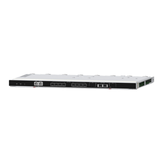
Ports Port numbering The ports on the switch module are numbered in the format of A/B/C: • A—IRF member device ID. By default, switch modules are not set up in an IRF fabric. The default value of A is 1. Devices with the same member ID cannot set up an IRF fabric. -
Page 32: Internal Ports
(3) 25-GE fiber ports (4) 100-GE fiber ports Table 2 External port description Number Port name Port type Quantity Description You can access the AMC CLI of the switch module from the port. The baud rate is 115200 bps. AMC serial port RJ-45 It can be used only by technical engineers to upgrade the AMC firmware version. -
Page 33: Leds And Buttons
LEDs and buttons Figure 4 LED and buttons (1) UID LED (2) RUN LED (3) Health LED (4) 25-GE fiber port LED (5) 100-GE fiber port/breakout interface LEDs • The eight 25-GE fiber port LEDs are the same in appearance. One of these LEDs is marked in the figure for illustration. - Page 34 firmware is being upgraded from the OM. • Off—The UID LED is not activated. • Steady green/off—A system failure has occurred. • Flashing green (4 Hz)—The system is being loaded. RUN LED (RUN) • Flashing green (1 Hz)—The system is operating correctly. •...
-
Page 35: Logical Architecture
Logical architecture As shown in Figure 5, the switch module contains three logical units: • CPU unit—As the control and management core of the switch module, it is responsible for module management, system configuration, and special packet processing. • AMC unit—As the auxiliary management unit of the switch module, it is responsible for data collection and report, power up/down control of the module, and system monitoring. - Page 36 Figure 6 Switch module installation slots (1) ICM1 slot (2) ICM2 slot (3) ICM3 slot (4) ICM4 slot (5) ICM5 slot (6) ICM6 slot...
-
Page 37: Internal Connections
Internal connection diagram between mezzanine network Blade server model switch modules and mezzanine network adapters on the adapters server H3C UniServer B5700 G5 Figure 7 NOTE: The connection diagrams are H3C UniServer B5700 G3 Figure 7 logical diagrams, presenting the... - Page 38 Figure 7 Switch module and mezzanine network adapter internal connections (method 1) LOM P1 LOM P2 Embedded Mezz1 Mid-plane Mezz2 Mezz3 Blade Switch module and mezzanine network adapter internal connections (method 2) As shown in Figure 8, switch modules and mezzanine network adapters are collected as follows: •...
-
Page 39: Switch Module And Mezzanine Network Adapter Port Connections
Figure 8 Switch module and mezzanine network adapter internal connections (method 2) LOM P1 LOM P2 Embedded Mezz1 Mid-plane Mezz2 Mezz3 Mezz4 Mezz5 Mezz6 Blade Switch module and mezzanine network adapter port connections Before configuring mezzanine network adapters on the blade server, identify the connections between the mezzanine network adapter ports and switch modules. -
Page 40: Hardware Compatibility
Hardware compatibility Mezzanine network adapters compatible with the switch module Table 6 describes the mezzanine network adapters compatible with the BX1010E switch modules. Table 6 Mezzanine network adapters compatible with the BX1010E switch modules Mezzanine network adapter Port quantity Description model 4-port 10Gb Ethernet mezzanine network NIC-ETH561i-Mb-4*10G... - Page 41 Transceiver Central Max transmission Type Remarks module/cable model wavelength distance • 380 m (1246.72 ft) (4G) • 500 m (1640.42 ft) (2G) • 100 m (328.08 ft) (16G) • 150 m (492.13 ft) SFP-FC-16G-SW-MM850- 16G/8G/4G FC fiber 850 nm (8G) port transceiver module •...
- Page 42 SFP-25G-SR-MM850-1-X 50/125 µm, MMF 100 m (328.08 ft) QSFP+ transceiver modules QSFP-40G-SR4-MM850- 50/125 µm, MMF 150 m (492.13 ft) QSFP-40G-SR4-MM850 50/125 µm, MMF 150 m (492.13 ft) 850 nm QSFP-40G-CSR4-MM85 50/125 µm, MMF 400 m (1312.34 ft) 0-CM QSFP-40G-SR4-MM850 50/125 µm, MMF 400 m (1312.34 ft) QSFP28 transceiver modules QSFP-100G-SR4-MM850...
- Page 43 SFP+ copper cables SFP-XG-CAB-3M-CM 3 m (9.84 ft) LSWM3STK 3 m (9.84 ft) SFP+ copper cable SFP-XG-CAB-5M-CM 5 m (16.40 ft) LSTM1STK 5 m (16.40 ft) SFP28 copper cables SFP-25G-D-CAB-3M 3 m (9.84 ft) SFP28 copper cable SFP-25G-D-CAB-3M-CM 3 m (9.84 ft) QSFP+ copper cables QSFP-40G-3M-CM 3 m (9.84 ft)
- Page 44 IMPORTANT: • As a best practice, use H3C transceiver modules and cables for the switch module. For the specifications of H3C transceiver modules and cables, see H3C Transceiver Modules User Guide. • H3C transceiver modules and cables are subject to change over time. For the most up-to-date list of H3C transceiver modules and cables, contact H3C Support or marketing staff.
-
Page 45: Appendix B Technical Support
Appendix B Technical support If you encounter any complicated problems during daily maintenance or troubleshooting, contact H3C Support. Before contacting H3C Support, collect the following server information to facilitate troubleshooting: • Log and sensor information: • Product serial number. •... -
Page 46: Appendix C Product Recycling
Appendix C Product recycling New H3C Technologies Co., Ltd. provides product recycling services for its customers to ensure that hardware at the end of its life is recycled. Vendors with product recycling qualification are contracted to New H3C to process the recycled hardware in an environmentally responsible way. -
Page 47: Appendix D Glossary
Appendix D Glossary Item Description A module that supports hot swapping (a hot-swappable module) can be installed or Hot swapping removed while the server is running without affecting the system operation. A mechanism that ensures high availability and business continuity by providing Redundancy backup modules. -
Page 48: Appendix E Acronyms
Appendix E Acronyms Acronym Full name App Engine Auxiliary Management Controller Command-line interface Fiber Channel FCoE Fibre Channel over Ethernet FCoE Forwarder Interconnect module Intelligent Resilient Framework Mezz Mezzanine N_Port Virtualization Onboard Manager Serial Over LAN Secure Shell Unit identification...