Table of Contents
Advertisement
Quick Links
Advertisement
Table of Contents

Related Manuals for Control 4 C4-KNX-THERM Series


Summary of Contents for Control 4 C4-KNX-THERM Series
- Page 2 This manual describes the function and configuration of the Control Element 2/4-fold with RTC. Control Element 2/4-fold with RTC FM SKU C4-KNX-THERM-xx (KNXPROD File Name: SBR/U2.1.41-83. Download: http://ctrl4.co/knx-therm). Subject to change. Exclusion of liability: Although the contents of this document have been checked to ensure that they are consistent with the hardware and software, deviations cannot be completely excluded.
- Page 3 Technical Reference Manual Tabl e of contents Information and symbols used ........................9 Intended use ..............................10 Improper use ..............................10 Target group / Qualifications of personnel ....................11 2.4.1 Operation ..............................11 2.4.2 Installation, commissioning and maintenance ..................... 11 Safety instructions ............................
- Page 4 Table of contents 10.2.13 Basic stage heating - Status object heating....................39 10.2.14 Basic stage heating - Mode of the control value ..................39 10.2.15 Basic stage heating - Hysteresis (x 0.1°C) ....................40 10.2.16 Basic stage heating - Control value difference for sending of heating control value ........40 10.2.17 Basic stage heating - Cyclic sending of the control value (min) ..............
- Page 5 Table of contents 10.2.66 Combined heating and cooling modes - Additional heating/cooling stage control value output....58 10.2.67 Setpoint settings ............................58 10.2.68 Setpoint settings - Setpoint for heating comfort = setpoint for cooling comfort ........... 58 10.2.69 Setpoint settings - Hysteresis for switchover heating/cooling (x 0.1°C) ............59 10.2.70 Setpoint settings - Setpoint temperature for heating and cooling comfort (°C) ...........
-
Page 6: Table Of Contents
Table of contents 10.2.119 Fan coil settings for cooling - Speed level 1 to 5 up to control value (0 to 255) cooling ......72 10.2.120 Fan coil settings for cooling - Fan speed level limit cooling for eco mode........... 72 10.2.121 Fan coil settings for cooling - Maximum fan speed level cooling for eco mode........... - Page 7 Table of contents 10.4.32 Outside temperature for summer compensation ..................89 10.4.33 Summer compensation active........................90 10.4.34 Setpoint reached ............................90 10.4.35 Fahrenheit ..............................90 10.4.36 Display backlighting ............................. 91 10.4.37 On/Off request ............................. 91 10.4.38 Setpoint display ............................91 10.4.39 Request setpoint ............................
- Page 8 Notes on the instruction manual Please read through this manual carefully and observe the information it contains. This will assist you in preventing injuries and damage to property and ensure both reliable operation and a long service life for the device. Please keep this manual in a safe place.
- Page 9 Notes on the instruction manual The device has been constructed according to the latest valid regulations governing technology and is operationally reliable. It has been tested and left the factory in a technically safe and reliable state. However, residual hazards remain. Read and adhere to the safety instructions to prevent hazards of this kind.
- Page 10 Notes on the instruction manual The device is intended for the following: ■ the control of a ventilator convector with a fan coil actuator. ■ the control of conventional heating and cooling installations. ■ operation according to the listed technical data. ■...
- Page 11 Notes on the instruction manual No special qualifications are needed to operate the device. Installation, commissioning and maintenance of the device must only be carried out by trained and properly qualified electrical installers. The electrical installer must have read and understood the manual and follow the instructions provided.
- Page 12 Notes on the instruction manual Danger - Electric voltage! Electric voltage! Risk of death and fire due to electric voltage of 230 V. Dangerous currents flow through the body when coming into direct or indirect contact with live components. This can result in electric shock, burns or even death.
- Page 13 Notes on the instruction manual Consider the protection of the environment! Used electric and electronic devices must not be disposed of with domestic waste. – The device contains valuable raw materials which can be recycled. Therefore, dispose of the device at the appropriate collecting depot. All packaging materials and devices bear the markings and test seals for proper disposal.
- Page 14 Notes on the instruction manual The Control Element 2/4-fold with RTC (room temperature controller) FM (flush-mounting) mounts on a flush-mounted bus/network coupler (C4-KNX-BC). The room temperature controller senses the current room temperature and regulates the heating or cooling. The device also serves to control two-/four-pipe systems (2-/4-pipe fan coil units) and conventional air-conditioning units.
- Page 15 Notes on the instruction manual The following table lists the options for use: Special features Function General functions ■ ■ ■ Function illumination Set / actual temperature Light scene actuator ■ ■ ■ Freely programmable Comfort/standby Sequence ■ ■ ■ Day / night switchover of the Night mode Logic...
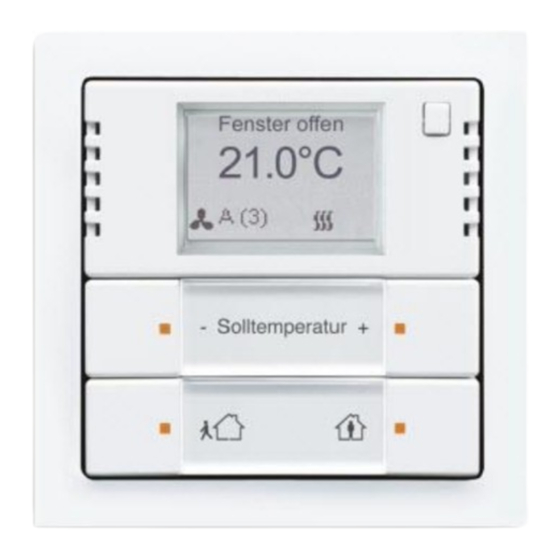
- Page 16 Notes on the instruction manual [1] ECO button [2] Labelling field [3] Menu button [4] Setpoint adjustment [5] LED [6] Display [7] Switchover button Fig. 1: Overview of devices (front view) NOTE Please observe the special mounting instructions at Chapter 6 “Connection, installation / mounting“...
- Page 17 Notes on the instruction manual Designation Value Power supply ■ Bus coupler: 24 V DC (via bus line) ■ Network coupler: 230 V AC / 50 Hz Bus subscribers: Maximum 12 mA KNX connection ■ Bus coupler: Bus connecting terminal, screwless ■...
- Page 18 Notes on the instruction manual Danger - Electric voltage! Risk of death due to electrical voltage of 230 V during short-circuit in the low- voltage line. – Low-voltage and 230 V cables must not be installed together in a flush- mounted socket! Danger - Electric voltage! Install the device only if you have the necessary electrical engineering...
- Page 19 Notes on the instruction manual For proper commissioning please observe the following points: ■ The room temperature controller should be installed at a height of approximately 150 cm from the floor and 50 cm from a door frame. Fig. 3: Installation site - Distance ■...
- Page 20 Notes on the instruction manual ■ This also applies to the installation on an exterior wall. – Low outside temperatures have an effect on temperature regulation. Fig. 7: Installation site - Exterior wall ■ Wetting the room temperature controller with fluids is to be avoided. Installation site –...
- Page 21 Notes on the instruction manual Caution! The device can sustain damage when coming into contact with hard objects! The plastic parts of the device are sensitive. – Pull the attachment off only with your hands. – Do not lever parts off with screwdrivers or similar hard objects. Installation only in dry interior rooms on a flush-mounted bus/network coupler, which is to be ordered separately.
- Page 22 Notes on the instruction manual 3. Fix the device with the supplied screw. Fig. 12: Fixing the device 4. Plug the rocker back onto the device. Fig. 13: Plugging the rocker on – The rockers have twist protection to ensure that they are attached the right way around.
- Page 23 Notes on the instruction manual Carry out the electrical connection 24 V DC according to the circuit diagram. Fig. 16: Connection of bus coupler Carry out the electrical connection according to the circuit diagram. 230 V Fig. 17: Connection of network coupler │23...
- Page 24 Notes on the instruction manual To start the device a physical address must be assigned first. The physical address is assigned, and the parameters are set with the Engineering Tool Software ETS (ETS 5.6.6 or higher). NOTE The devices are products of the KNX system and meet KNX guidelines. Detailed expert knowledge by means of KNX training sessions for a better understanding is assumed.
- Page 25 Notes on the instruction manual [1] Setpoint adjustment [2] Setpoint adjustment [3] ECO button [4] Menu button [5] Switchover button Fig. 18: Control elements (front view) The room temperature controller is operated via buttons [1 + 2 + 3 + 4] beneath the display. The additional button [5] next to the display is used for switching over to the menu level.
- Page 26 Notes on the instruction manual Display Function Action of the device – Heating/cooling is at the normal level. Comfort mode – The display is only visible when the "Superimposed operating mode" is active. Local operation is blocked. – The heating/cooling output is slightly Standby mode lowered.
- Page 27 Notes on the instruction manual Operation is carried out by pressing the individual buttons. The functions of the buttons in connection with the display are described in the following. The precise function is fixed via the assigned application / function and their parameter settings. Extensive applications are available for the room temperature controller and the control elements.
- Page 28 Notes on the instruction manual Fig. 20: Rocker switch functions of the RTC adjustment level Adjusting the setpoint The setpoint is adjusted via the top rocker [1 / 2]. Adjusting the operating modes The operating modes are adjusted via the bottom rocker [3]. Confirming the menu selection The selection of the menu is confirmed via the bottom rocker [4].
- Page 29 Notes on the instruction manual The display of the room temperature controller in the standard view indicates the current setpoint for the temperature or the icon of the current function and the operating status (also alarm!). The current fan speed level is shown in the bottom left area of the display and the current operating mode in the bottom right area.
- Page 30 Notes on the instruction manual NOTE Menu sequence: Setpoint adjustment → Fan speed levels → Heating/cooling switchover → Setpoint adjustment → … – The menu function must be parameterized (otherwise only the setpoint adjustment is active)! – The setpoint adjustment is the primary function. If it is not actuated the menu jumps automatically back to the setpoint adjustment.
- Page 31 Notes on the instruction manual Selecting fan speed levels: 1. Activate the function via the button [4], if it is not active. – Keep pressing the button [4] until the "Fan speed levels" function is displayed. 2. Select the fan speed level. –...
- Page 32 Notes on the instruction manual Display Operating mode Standby: – Standby mode lowers the temperature during absence below the level of comfort mode. This saves energy. And the room does not cool down during an extended absence. Dew point: – If an appropriate telegram is received from a dew point sensor, the room temperature controller will display the corresponding icon and cease cooling and merely protect against the heat.
- Page 33 Notes on the instruction manual Caution! - Risk of damaging the device! ■ When spraying on cleaning agents, these can enter the device through crevices. – Do not spray cleaning agents directly onto the device. ■ Aggressive cleaning agents can damage the surface of the device. –...
- Page 34 Description of application and parameters Application program The following application program is available: Application program Continuous / switching heating cooling TP/7 The application program for the room temperature controller contains the applications listed in the following: KNX application Continuous / switching heating cooling TP/7 Control settings Button top right General functions...
- Page 35 Description of application and parameters Application program Options: Single device Master device Slave device – Single device: The device is used singly in a room as room temperature controller. – Master device: At least two room temperature controllers are located in one room. One device is to be set up as a master device, while the others are to be programmed as slave devices / temperature sensors.
- Page 36 Description of application and parameters Application program – Heating and cooling with an additional stage: In addition to the heating and cooling functions, one additional stage each with an autonomous controller type can be programmed. Note This parameter is only available if the "Device function" parameter is set on "Single device"...
- Page 37 Description of application and parameters Application program Options: Setting option between 5 - 3000 minutes – The "In operation" communication object serves to inform that the controller still operates. Value "1" is sent cyclic. This parameter is used to set the cycle for sending. If the cyclic telegram fails, the function of the device is faulty, and the air-conditioning of the room can be maintained with a forced operation.
- Page 38 Description of application and parameters Application program PI continuous, 0 – 100% and PI PWM, On/Off: Options: ■ Area (e.g. floor heating) 4°C 200 min ■ Convector (e.g. heater) 1.5°C 100 min ■ Free configuration Fan coil: ■ Fan coil 4°C 90 min ■...
- Page 39 Description of application and parameters Application program Options: Setting option between 0 - 255 The I-component refers to the reset time of a control. The integral component has the effect of moving the room temperature slowly toward, and ultimately reaching, the setpoint value. Depending on the type of system used, the reset time has to have different values.
- Page 40 Description of application and parameters Application program Options: Setting option between 3 - 255 The hysteresis of the two-point controller specifies the fluctuation range of the controller around the setpoint value. The lower switching point is located at "Setpoint value minus hysteresis" and the upper point is at "Setpoint value plus hysteresis".
- Page 41 Description of application and parameters Application program Options: Setting option between 1 - 60 minutes In PI PWM, On/off the control value percentage values are converted into a pulse-interval signal. This means that a selected PWM cycle will be divided into an on-phase and an off-phase based on the control value.
- Page 42 Description of application and parameters Application program Options: 2-point 1 bit, Off/On 2-point 1 byte, (0/100%) PI continuous, 0-100% PI PWM, On/Off Fan coil The actuation of the control valve is determined by the selection of the controller type. – 2-Point 1 Bit, Off/On: The 2-point control is the simplest type of control.
- Page 43 Description of application and parameters Application program PI continuous, 0 – 100% and PI PWM, On/Off: Options: ■ Area (e.g. floor heating) 4°C 200 min ■ Convector (e.g. heater) 1.5°C 100 min ■ Free configuration Fan coil: ■ Fan coil 4°C 90 min ■...
- Page 44 Description of application and parameters Application program Options: Setting option between 0 - 255 The I-component refers to the reset time of a control. The integral component has the effect of moving the room temperature slowly toward, and ultimately reaching, the setpoint value. Depending on the type of system used, the reset time has to have different values.
- Page 45 Description of application and parameters Application program Options: Setting option between 3 - 255 The hysteresis of the two-point controller specifies the fluctuation range of the controller around the setpoint value. The lower switching point is located at "Setpoint value minus hysteresis" and the upper point is at "Setpoint value plus hysteresis".
- Page 46 Description of application and parameters Application program Options: Setting option between 1 - 60 minutes The current control value used by the device can be cyclically transmitted to the bus. Note This parameter is only available when the "Control value type" parameter is set either on "2-point 1 Bit, Off/On", "2-point 1 Byte, 0/100%", "PI continuous, 0- 100%"...
- Page 47 Description of application and parameters Application program Note Only available when the "Device function" parameter is set on either "Single device" or "Master device" and the control function parameter is set on either "Cooling", "Cooling with additional stage", "Heating and cooling" or "Heating and cooling with additional stages".
- Page 48 Description of application and parameters Application program PI continuous, 0 – 100% and PI PWM, On/Off: Options: ■ Area (e.g. cooling ceiling) 5°C 240 min ■ Free configuration Fan coil: ■ Fan coil 4°C 90 min ■ Free configuration Two cooling types (area or fan coil) with preset parameters are available to the user. If the required cooling type is not available, individual parameters can be specified in free configuration.
- Page 49 Description of application and parameters Application program Options: This parameter enables additional functions and communication objects, e.g. "Basic stage cooling". Note Only available when the "Extended settings" parameter under "Cooling control" is set on "Yes". Options: This parameter enables the "Status cooling" communication object. Options: Normal Inverse...
- Page 50 Description of application and parameters Application program Options: Setting option between 3 - 255 The hysteresis of the two-point controller specifies the fluctuation range of the controller around the setpoint value. The lower switching point is located at "Setpoint value minus hysteresis" and the upper point is at "Setpoint value plus hysteresis".
- Page 51 Description of application and parameters Application program Note Only available when the "Extended settings" parameter under "Cooling control" is set on "Yes". Options: Setting option between 0 - 255 The maximum control value of the PI controller defines the maximum value outputted by the controller.
- Page 52 Description of application and parameters Application program Note Only available when the "Device function" parameter is set on either "Single device" or "Master device" and the control function parameter is set on either "Cooling with additional stage" or "Heating and cooling with additional stages". Options: 2-point 1 bit, Off/On 2-point 1 byte, (0/100%)
- Page 53 Description of application and parameters Application program PI continuous, 0 – 100% and PI PWM, On/Off: Options: ■ Area (e.g. cooling ceiling) 5°C 240 min ■ Free configuration Fan coil: ■ Fan coil 4°C 90 min ■ Free configuration Two cooling types (area or fan coil) with preset parameters are available to the user. If the required cooling type is not available, individual parameters can be specified in free configuration.
- Page 54 Description of application and parameters Application program Options: This parameter enables additional functions and communication objects, e.g. "Additional cooling stage". Note Only available when the "Extended settings" parameter under "Control of additional cooling stage" is set on "Yes". Options: Normal Inverse The mode of the control value can be used to adapt the control value to de-energised opened (normal) or de-energised closed (inverse) valves.
- Page 55 Description of application and parameters Application program Options: The control values of the 0 - 100% PI continuous controller are not transmitted after every calculation. Instead, they are transmitted when the calculation results in a value that is different enough to the previous sent value to make a transmission meaningful. This value difference can be entered here.
- Page 56 Description of application and parameters Application program Options: Setting option between 0 - 255 The minimum control value of the PI controller defines the minimum value output by the controller. If a minimum value greater than zero is chosen, the controller will not output a lower value, even if it calculates a value that is lower.
- Page 57 Description of application and parameters Application program Options: Automatic Only via object On-site/via extension unit and via object This function makes it possible to switch between the heating and cooling mode of the device. – Automatic: E.g. for four-conductor systems which allow the switchover between heating and cooling at all times.
- Page 58 Description of application and parameters Application program Options: Via 1 object Via 2 objects This parameter is used to define whether the control value is transmitted to the climate control actuator using one or two objects. If the climate control actuator has separate control value inputs for heating and cooling, or if separate actuators are used, then the option "Via 2 objects"...
- Page 59 Description of application and parameters Application program Options: Setting option between 5 - 100 This parameter specifies the one-sided hysteresis for switching between heating and cooling when "Setpoint heating comfort = Setpoint cooling comfort" is active. If the room temperature exceeds the setpoint temperature value plus hysteresis, the system switches to cooling.
- Page 60 Description of application and parameters Application program Options: Setting option between 0 - 15 Specifies the temperature in heating mode when nobody is present. On devices with a display, this mode is indicated by the eco icon. Options: Setting option between 5 - 15 Function for protecting the building against the cold.
- Page 61 Description of application and parameters Application program Options: Setting option between 0 - 15 Specifies the temperature in cooling mode when nobody is present. On devices with a display, this mode is indicated by the eco icon. Note This parameter is only available when the "Control function" parameter is set on "Cooling", "Cooling with additional stage", "Heating and cooling"...
- Page 62 Description of application and parameters Application program Options: Cyclic and during change Only for change The current setpoint value can be sent to the bus either cyclically and after a change, or only after a change. Options: Setting option between 5 - 240 This parameter is used to specify the amount of time that will elapse before the current setpoint value is automatically transmitted.
- Page 63 Description of application and parameters Application program │63...
- Page 64 Description of application and parameters Application program Options: Setting option between 0 - 15 This preset can be used to limit the manual increase during cooling. Note This parameter is only available when the "Control function" parameter is set on "Cooling", "Cooling with additional stage", "Heating and cooling"...
- Page 65 Description of application and parameters Application program Options: If the device switches to a new operating mode, the manual adjustment is deleted and the parameterized setpoint temperature for the operating mode plus any change by the base setpoint value object will be applied if this parameter is activated. Example: Comfort temperature of 21°C plus manual adjustment of 1.5°C = 22.5°C.
- Page 66 Description of application and parameters Application program Options: Internal and external measurement 2 x external measurement Internal and 2x external measurement Specifies the temperature reading inputs for the weighted measurement, in which the calculated weighted average of the inputs is used as an input value for control Note This parameter is only available when the "Inputs of temperature reading"...
- Page 67 Description of application and parameters Application program Options: Setting option between 5 - 240 The current actual temperature used by the device can be cyclically transmitted to the bus. Options: Setting option between 1 - 100 If the change in temperature exceeds the parameterized difference between the measured actual temperature and the previous actual temperature that was sent, the changed value will be transmitted.
- Page 68 Description of application and parameters Application program Options: Cooling Heating In the event of a failure of the actual temperature measurement, the device will no longer be able to independently specify the heating/cooling operating type. As a result, the operating type best suited to protecting the building will be selected.
- Page 69 Description of application and parameters Application program Options: When refrigerating machines are used, dew may appear on the refrigerant supply lines during operation as a result of excessive cooling and/or humidity. The dew indicator reports the dew formation via the "Dew point alarm" object (receiving only). This causes the controller to switch to a protective mode.
- Page 70 Description of application and parameters Application program Options: 0..5 0..255 1 bit m off n 1 bit m 1 off n – 0 to 5: The level values (0..3 or 0..5) are output in the 1-byte format as the counter values 0..3 or 0..5.
- Page 71 Description of application and parameters Application program Options: The controller obtains the current fan speed level for controlling a fan coil actuator either by calculating it from the table of level values under "Fan coil settings for heating" or "Fan coil settings for cooling", or by receiving feedback from the fan coil actuator.
-
Page 72: Fan Coil Settings For Cooling - Speed Level 1 To 5 Up To Control Value (0 To 255) Cooling
Description of application and parameters Application program Options: Setting option between 0 - 5 Specifies the maximum possible fan speed level when the system is switched to eco mode. Note This parameter is only available if the "Device function" parameter is set on either "Single device"... -
Page 73: Summer Compensation
Description of application and parameters Application program Note This parameter is only available if the "Device function" parameter is set on either "Single device" or "Master device". Options: In order to save energy, and to ensure that the temperature difference occurring during entry and exit of a climate-controlled building stays within comfortable limits, the excessive reduction of room temperature should be prevented during high temperatures in the summer ( Summer compensation according to DIN 1946). -
Page 74: Summer Compensation - (Lower) Starting Temperature For Summer Compensation (°C)
Description of application and parameters Application program an outside temperature of 32°C; and 27°C at an outside temperature of 33°C. Options: Setting option between -127 - 127 The parameter defines the lower outside temperature value up to which temperature value the setpoint correction (summer compensation) is performed based on too high an outside temperature. - Page 75 Description of application and parameters Application program Options: Setting option between -127 - 127 The parameter is used to define how many degrees Kelvin the setpoint value will be increased by during summer compensation when the upper temperature value is reached. Typical values for summer compensation are: ■...
-
Page 76: Additional Rtc Application "Control Settings
Description of application and parameters Application program Options: 10 s 20 s 30 s 1 min. 2 min. 3 min. The parameter is used to specify the time period of non-operation after which there is a jump- back to the first function of the control element. Options: °C °F... -
Page 77: General - Display Of Actual Temperature
Description of application and parameters Application program Options: If the actual temperature is to be shown on the display, the parameter must be set on active. The device will then primarily display the actual temperature. When actuating the control element the display changes to the setpoint adjustment. After non-actuation of the control element the current actual temperature again appears in the display after the set waiting period. -
Page 78: Brightness Setting - Day/Night Mode
Description of application and parameters Application program Options: Via the activated communication object "Day/Night" the backlighting of the display is shown bright during day mode and darker during night mode. Note The operation only applies to the display. It does not apply to the backlighting of the buttons. -
Page 79: Communication Objects - Rtc
Description of application and parameters Application program Number Name Object function Data type Heating control value (control Output 1. Switching value heating/cooling) 2. Percent (0 to 100%) Description: 1. This object is used to operate a switching actuating drive, e.g. a thermoelectric positioner, that is controlled by a switching/heating actuator. -
Page 80: Additional Cooling Stage
Description of application and parameters Application program Number Name Object function Data type Additional cooling stage Output 1. Switching 2. Percent (0 to 100%) Description: 1. This object is used to operate a switching actuating drive, e.g. a thermoelectric positioner, that is controlled by a switching/heating actuator. -
Page 81: External Actual Temperature
Description of application and parameters Application program Note An external temperature measurement for room control may be practical for larger rooms and/or floor heating. Number Name Object function Data type External actual temperature Input 2-byte floating point value 2-byte communication object for reading an external temperature value provided via the KNX bus. -
Page 82: Current Setpoint
Description of application and parameters Application program Number Name Object function Data type 2-byte floating point Current setpoint Output value The object outputs the current setpoint temperature resulting from the following: the parameterized setpoint temperature of the current operation type and operating mode, the manual setpoint temperature adjustment, a change in the base setpoint temperature via the base setpoint value object. -
Page 83: Superimposed Operating Mode
Description of application and parameters Application program Number Name Object function Data type 1. Superimposed operating Input HVAC mode mode 2. Superimposed operating Input HVAC mode mode (master/slave) The "Superimposed operating mode" object receives the operating mode that is to be set as 1- byte value. -
Page 84: Presence Detector
Description of application and parameters Application program Number Name Object function Data type 1. Presence detector Input Switching 2. Presence detector Input Switching (master/slave) This object transmits the value 1 to the controller to signal that there are people in the room. If not other object with a higher priority is present, then the "Presence detector"... -
Page 85: Basic Load
Description of application and parameters Application program Number Name Object function Data type Basic load Input / output Switching This object uses the value 1 to activate a parameterized base load, i.e. a minimum control value greater than zero. The value 0 deactivates the base load. When the base load is deactivated, the control value can be lowered all the way to zero if necessary when the setpoint temperature is reached, despite the minimum value set in the parameter. -
Page 86: Fan Coil Manual
Description of application and parameters Application program Number Name Object function Data type 1. Fan coil manual Output Switching 2. Fan coil manual (master) Output Switching 3. Fan coil manual (slave) Output Switching Using this 1-bit communication object, a fan coil actuator can be placed in manual fan mode or returned to automatic fan mode. -
Page 87: Fan Coil Step Status
Description of application and parameters Application program Number Name Object function Data type 2-byte floating point Fan coil step status Input / output value Using the "Fan coil step status" object, the room temperature controller receives the current fan speed level of the fan coil actuator. Number Name Object function... -
Page 88: Fan Speed Level 5
Description of application and parameters Application program Number Name Object function Data type Fan speed level 5 Output Switching This 1-bit communication object is used to output the active status (1) of the fan speed level, while the other fan speed levels are deactivated (0), depending on the parameter setting. If the fan speed level is inactive, the object has a value of (0). -
Page 89: Condensate Water Alarm
Description of application and parameters Application program Number Name Object function Data type 1. Condensate water alarm Input Switching 2. Condensate water alarm Input Switching (master/slave) This 1-bit communication object is used to place the controller in the condensation alarm mode. This causes the current setpoint value to be set to the heat protection setpoint value in order to keep the structure from being damaged by an overflowing condensation container. - Page 90 Description of application and parameters Application program Number Name Object function Data type Summer compensation active Output Switching This 1-bit communication object is used to indicate via the bus whether the summer compensation is active (1) or inactive (0). If it is active, the setpoint value configured for the cooling mode is increased by the summer compensation function.
- Page 91 Description of application and parameters Application program Number Name Object function Data type Display backlighting Input / output Switching The display backlighting is activated with value (1) and deactivated with value (0) via the 1-bit communication object. Note This function is mainly used in rooms where backlighting during the night is considered to be a disturbing factor, such as in hotel rooms and bedrooms.
- Page 92 Description of application and parameters Application program Number Name Object function Data type 1. Heating/cooling request Input Switching (master) 2. Heating/cooling request Input Switching (slave) This 1-bit communication object must be connected to the respective slave communication object in order to synchronise the devices in the master/slave configuration. Number Name Object function...
- Page 93 Description of application and parameters Application program Number Name Object function Data type 2-byte floating point Controller status RHCC Output value This communication object outputs the heating/cooling operation type, active/inactive operation, the frost and heat alarm, and the error (actual temperature reading failure) in accordance with the specification for the RHCC (Room Heating Cooling Controller) status.
- Page 94 Description of application and parameters Application program Number Name Object function Data type – Day/Night mode Switching Description: Via the activated communication object "Day/Night" the backlighting of the display is shown bright during day mode and darker during night mode. Note: The operation only applies to the display.
- Page 95 Description of application and parameters Application program When actuated or released a switching telegram is sent out. In each case, the application makes a separate set of parameters and communication objects available for the 1st and the 2nd button. The other side of the button can be assigned a further "button-oriented" function. Parameter General parameter Setting options...
- Page 96 Description of application and parameters Application program The push-buttons have communication objects for switching and dimming. A distinction is made between a short (switching) and long (dimming) press of the button. In each case, the application makes a separate set of parameters and communication objects available for the 1st and the 2nd button.
- Page 97 Description of application and parameters Application program With an actuation of the 1st or 2nd button a telegram with a predefined value is sent out. The application differentiates here between whether the 1st or 2nd button is actuated. Parameter General parameter Setting options Comments –...
- Page 98 Description of application and parameters Application program Objects Object name Data type Flags Switching value (1 bit) 1 bit EIS1 / DPT 1.001 C, W ,T ,U Switching value (1 byte 0 - 100%) 1 byte EIS6 / DPT 5.001 C, W ,T ,U Switching value (1 byte 0 - 255) 1 byte EIS14 / DPT 5.010...
- Page 99 Description of application and parameters Application program When actuating and/or releasing the buttons, two telegrams with predefined values are sent from two different communication objects. In each case, the application makes a separate set of parameters and communication objects available for the 1st and the 2nd button. The application makes it possible, for example, to send out a switching function and a floating point value when actuating one side of the button and to assign an additional "button-oriented"...
- Page 100 Description of application and parameters Application program Additional Parameters Setting options Comments – Reaction on rising edge No reaction Value 1 Value 2 Alternating value1/value2 – Reaction on falling edge No reaction Value 1 Value 2 Alternating value1/value2 – Value 1 / 2 for a rising Only available when edge parameter "Reaction to rising...
- Page 101 Description of application and parameters Application program Objects Object name Data type Flags Switching (rising edge) (1 bit) 1 bit EIS1 / DPT 1.001 C, W ,T ,U Switching (rising edge) (1-byte 0 - 100%) 1 byte EIS6 / DPT 5.001 C, W ,T ,U Switching (rising edge) (1-byte 0 - 255) 1 byte EIS14 / DPT 5.010...
- Page 102 Description of application and parameters Application program When a button is actuated a predefined light scene number is called up. In each case, the application makes a separate set of parameters and communication objects available for the 1st and the 2nd button. The application makes it possible to call up a light scene via one button side while the other button side can be assigned with a further "button-oriented"...
- Page 103 Description of application and parameters Application program Different switching processes are triggered with each new actuation of the 1st or 2nd button. For example: ■ First actuation (2nd button) switches lamp 1 on. ■ Second actuation (2nd button) switches lamp 1 off and lamp 2 on. ■...
- Page 104 Description of application and parameters Application program The application makes two separate functions available on one side of the button which can be called up via a short or long button press, while the other side of the button can be assigned a further "button-oriented"...
- Page 105 Description of application and parameters Application program Via the "Cyclic telegram" application and after receipt of a telegram on the "Input" object, a telegram with the same volume is cyclically sent out on the "Cyclic output" object. The object types for "Input" and "Output" can be collectively parameterised for the different applications. The times for cyclic sending on the "Output"...
- Page 106 Description of application and parameters Application program The "Priority" application has 3 communication objects, a 1-bit object "Switch input", a 2-bit object "Input priority" and a 1-bit object "Output". The telegrams received on the "Switch input" are transferred to the "Output" depending on the state of the "Input priority" object. The 2-bit object "Input priority"...
- Page 107 Description of application and parameters Application program Logic objects Object name Data type Flags Output (1 bit) 1 bit EIS1 / DPT 1.001 C, W, T Output (1 byte) 1 byte EIS14 / DPT 5.010 C, W, T Input 1 (1 bit) 1 bit EIS1 / DPT 1.001 C, W, U Input 1 (1 byte)
- Page 108 Description of application and parameters Application program The "Gate" application allows specific signals to be filtered and the signal flow to be temporarily blocked. The function has three communication objects: "Control input", "Input" and "Output". The input or output object can assume different sizes. The bit size can be freely assigned with the "Not assigned"...
- Page 109 Description of application and parameters Application program With the "Staircase lighting" application, switching telegrams or value telegrams can be provided with a switch-off delay. Depending on the parameterisation, the application shows different communication objects: – a 1-bit object for input and output If an ON telegram is received via the "Input/Output"...
- Page 110 Description of application and parameters Application program Telegrams can be received via the "Input" object using the "Delay" application. The telegrams received are sent out on the "Output" object with a set delay time. The object types for "Input" and "Output" can be collectively parameterised for the different applications.
- Page 111 Description of application and parameters Application program Up to eight input values can be compared with each other using the "Min/max value transducer" application. The application can output the highest input value, the smallest input value or the average of all input values on the output. The size of the input objects, and with it also the size of the output object can be adapted for the most diverse applications.
- Page 112 Description of application and parameters Application program With the "Threshold value / Hysteresis" application, value telegrams can be received on an input communication object and compared with threshold values specified in the device. Predefined values are sent out on the "Output" communication object if the upper threshold is exceeded or the lower threshold drops below the set value.
- Page 113 Description of application and parameters Application program With the "Light scene actuator" application it is possible to call up scenes that are stored in the device via the receipt of a scene number on the 1-byte communication object "Scene call-up". A maximum of eight scenes with up to eight actuator objects can be created.
- Page 114 Description of application and parameters Application program Basic stage cooling - Cyclic sending of the control value (min) ................50 Actual temperature .............. 79 Basic stage cooling - Hysteresis (x 0.1°C) ......50 Additional alarms ..............32 Basic stage cooling - Maximum control value (0 - 255) ..51 Additional components ............
- Page 115 Description of application and parameters Application program Control of additional heating stage - P-component (x 0.1°C) Fan coil settings heating - Fan speed level 1 to 5 up to ..................43 control value (0 to 255) heating........70 Control of heating with additional stage - Temperature Fan coil step status ..............86 difference to basic stage (x 0.1°C) .........
- Page 116 Description of application and parameters Application program Setpoint settings - Setpoint for heating comfort = setpoint for cooling comfort ..............58 Notes on the instruction manual ..........8 Setpoint settings - Setpoint temperature for cooling comfort (°C) .................60 Setpoint settings - Set-point temperature for frost protection On/Off request ..............
- Page 117 Description of application and parameters Application program │117 200-00547-A 06-26-2018 LW...