
Related Manuals for NANOTEC PD4-N5918X4204

Summary of Contents for NANOTEC PD4-N5918X4204
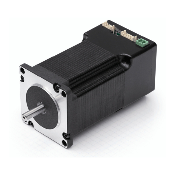
- Page 1 Technical Manual Plug & Drive Motors PD4-N NANOTEC ELECTRONIC GmbH & Co. KG Tel. +49 (0)89-900 686-0 Kapellenstraße 6 +49 (0)89-900 686-50 D-85622 Feldkirchen b. Munich, Germany info@nanotec.com...
- Page 2 Electronic GmbH & Co. KG Kapellenstraße 6 D-85622 Feldkirchen b. Munich, Germany Tel.: +49 (0)89-900 686-0 Fax: +49 (0)89-900 686-50 Internet: www.nanotec.com All rights reserved! MS-Windows 2000/XP/Vista are registered trademarks of Microsoft Corporation. Translation of the original operation manual Version/Change overview Version Date...
- Page 3 For criticisms, proposals and suggestions for improvement, please contact the above address or send an email to: info@nanotec.com Additional manuals Please also note the following manuals from Nanotec: NanoPro Configuration of controllers with the User Manual...
-
Page 4: Table Of Contents
Technical Manual PD4-N5918 Contents Contents Overview ..........................5 Connection and commissioning ..................8 Overview ..........................8 Connection diagram ....................... 9 Commissioning........................10 Connections and circuits ....................14 Inputs and outputs (JST PHD-12)..................14 Power supply (Phoenix connector) ..................16 RS485 network/CANopen (JST PHD-8) ................17 Operating modes........................ -
Page 5: Overview
Variants The PD4-N is available in the following variants that differ in holding torque, weight and length (see Section 6 “Technical data"): • PD4-N5918X4204 • PD4-N5918M4204 • PD4-N5918L4204 • PD4-N6018L4204 Firmware variants The Plug &... - Page 6 Technical Manual PD4-N5918 Overview Closed-Loop current control (sinusoidal commutation via the encoder): In contrast to conventional stepper motor positioning controls where only the motor is actuated or the position adjusted via the encoder, sinusoidal commutation controls the stator magnetic field via the rotary encoder as in a servomotor. The stepper motor acts in this operating mode as nothing more than a high pole servomotor, i.e.
- Page 7 Technical Manual PD4-N5918 Overview Activation via CANopen It is possible to include the stepper motor control in a CANopen environment with the PD4-N. The connection can be established either via 2 wires of the I/O connection cable or in a customer-specific version also via an M12 connector (5-pole). More detailed information on this can be found in the CANopen reference and in the NanoCAN user manual.
-
Page 8: Connection And Commissioning
Technical Manual PD4-N5918 Connection and commissioning Connection and commissioning Overview Plug connections The PD4-N Plug & Drive motor is equipped with the following plug connections: • JST PHD-12: inputs and outputs • JST PHD-8: RS485/CANopen • Phoenix connector: power supply Configuration The following figure shows the configuration of the connectors: Connection cable... -
Page 9: Connection Diagram
Technical Manual PD4-N5918 Connection and commissioning Connection diagram To operate the Plug & Drive motor, you must implement the wiring according to the following connection diagram. Issue: V 1.4... -
Page 10: Commissioning
Step Action Note Install the NanoPro control software on your PC. Download of www.nanotec.com See the NanoPro separate manual. Connect the PC to the RS485 interface of the Plug Connection diagram, & Drive motor according to the connection diagram. see Section 2.2. - Page 11 Proceed as follows to commission the Plug & Drive motor with the RS485 firmware: Step Action Note Install the NanoPro control software on your PC. Download of www.nanotec.com See the NanoPro separate manual. Connect the Plug & Drive motor according to the Connection diagram, see connection diagram. Section 2.2.
- Page 12 Technical Manual PD4-N5918 Connection and commissioning Step Action Note Check the current setting using the motor data Under no circumstances sheet on the <Motor Settings> tab. may the current be set to a value higher than the rated current of the motor. Select the "Movement"...
- Page 13 More detailed information can be found in the separate NanoCAN manual. Step Action Note Install the NanoCAN control software on your Download of www.nanotec.com Connect the Plug & Drive motor to the stepper Connection diagram, see motor according to the connection diagram. Section 2.2. Detailed information on connections can be found in Section 3.
-
Page 14: Connections And Circuits
Technical Manual PD4-N5918 Connections and circuits Connections and circuits Inputs and outputs (JST PHD-12) Introduction An overview of the assignments can be found in the connection diagram in Section 2.2. This section looks in detail at the assignment, functions and circuits of the connections. - Page 15 Technical Manual PD4-N5918 Connections and circuits Function of the inputs All digital inputs – with the exception of the "Clock" input in the clock directional mode – can be freely programmed using the NanoPro software (RS485) (e.g. as a limit position switch, enable, etc.) and can be used for sequential control with NanoJ.
-
Page 16: Power Supply (Phoenix Connector)
(xx=voltage: 12, 24 or 48 V, y=current: 2.5, 5 or 10 A) Information on the selection of the required power supply unit can be found in our FAQ on www.nanotec.com. Charging Z-K4700 or Z-K10000 condenser Note: Further information about accessories can be found on the Nanotec website: www.nanotec.com Issue: V 1.4... -
Page 17: Rs485 Network/Canopen (Jst Phd-8)
Technical Manual PD4-N5918 Connections and circuits RS485 network/CANopen (JST PHD-8) PD4-N in a network Generally, up to 254 (RS485) or 127 (CANopen) Plug & Drive motors can be actuated in a network from a PC or PLC. The number of PD4-N controllers in an RS485 network is limited to 32 by the hardware. - Page 18 Technical Manual PD4-N5918 Connections and circuits Notes on the baud rate It is important to note that both the controller and the CAN master use the same baud rate. Only this way can communication be established. The baud rate has a direct influence on the maximum possible bus length. The following list shows the possible baud rates as well as their maximum permissible bus lengths: Baud rate Bus length...
- Page 19 Technical Manual PD4-N5918 Connections and circuits Circuit diagram RS485 network Issue: V 1.4...
- Page 20 Technical Manual PD4-N5918 Connections and circuits Setting the RS485/CANopen module address Max. 127 addresses can be set which can, however, only be used to the full extent via CANopen as the maximum number of PD4-N controllers in an RS485 network is limited to 32 by the hardware.
-
Page 21: Operating Modes
Technical Manual PD4-N5918 Operating modes Operating modes Serial operating modes Introduction Depending on the travel profile, the motor can be operated using different operating modes. Due to the great capacity and functions available, it offers designers and developers a rapid and simple method of resolving numerous drive requirements with less programming effort. - Page 22 Technical Manual PD4-N5918 Operating modes Operation mode Application Clock direction mode, left Use this mode when you wish to operate the motor with a superordinate controller (e.g. CNC controller). Clock direction mode, right In the clock direction mode, the motor is operated via Clock direction mode two inputs with a clock and a direction signal from a Int.
-
Page 23: Canopen Operating Modes
Technical Manual PD4-N5918 Operating modes CANopen operating modes Introduction The motor can be operated using a total of 5 different operating modes in CANopen mode. More detailed information can be found in the separate NanoCAN manual. Overview of operating modes and their areas of application Operation mode Application Positioning mode... -
Page 24: Troubleshooting
Incorrect COM port selected. The port used can be found in the device manager of your PC. Communication cable not Use the recommended RS485 connected or interrupted converter from Nanotec: (incorrect RS485 converter • Order identifier: used). ZK-RS485-USB A non-existent motor number Set the correct module address. - Page 25 Technical Manual PD4-N5918 Troubleshooting Possible errors in CANopen mode Error Possible cause Rectification The wrong node ID has been On the <Configuration & NMT> tab communication set. in NanoCAN, select the node ID that with the is set on the rotary switches of the controller controller.
-
Page 26: Technical Data
Technical Manual PD4-N5918 Technical data Technical data Electrical connections Operating voltage V DC 12 V to 48 V ±4% Lower voltage limit: 11 V (undervoltage switch-off) Upper voltage limit: 50 V (overvoltage switch-off) Max. phase current Adjustable up to max. 4 A/phase Continuous current 3.2 A/phase Current drop Adjustable 0 to 150% of rated current... - Page 27 –10 °C to 40 °C Holding torque, weight and dimensions PD4-N5918 Variants Holding torque Weight Length “L" (Nm) (kg) (mm) PD4-N5918X4204 0.537 0.49 66.5 PD4-N5918M4204 1.13 0.80 PD4-N5918L4204 1.98 1.22 A complete set of datasheets is available for downloading at www.nanotec.com. Issue: V 1.4...
- Page 28 • Ambient temperature: 45 °C (50 °C, 55 °C, 60 °C for the comparative measurement) • Test motors: PD4-N5918X4204 and PD4-N5918L4204 • Measurement point: rear of motors for power transistors, on the outside of the housing The following graphics show the temperature test results:...
- Page 29 Technical Manual PD4-N5918 Technical data Operating voltage 24 V (PD4-N5918X4204) Operating voltage 24 V (PD4-N5918L4204) Issue: V 1.4...
- Page 30 Technical Manual PD4-N5918 Technical data Operating voltage 48 V (PD4-N5918X4204) Operating voltage 48 V (PD4-N5918L4204) Issue: V 1.4...
-
Page 31: Index
Technical Manual PD4-N5918 Index Index Accessories for voltage supply......16 Operating modes CANopen........... 23 serial............21 CANopen ..........7, 13, 17 Operating voltage.......... 16 Closed-Loop current control ......6 Output circuits ..........15 Commissioning ..........10 Outputs ............14 Overtemperature protection......28 Dimensions............27 dspDrive............6 Phoenix connector ........