Advertisement
Quick Links
Bus Ethernet Gateway
Installation Guide
Introduction
The Control4® Bus Ethernet Gateway (C4-DIN-BEG-V2) is intended for use in a
Control4 system. This device installs in a Control4 Centralized Lighting panel or in
any standard DIN rail panel with 35 mm rails. The Bus Ethernet Gateway provides
the communication bridge between keypads on the RS-485 bus and the Control4
system. For RS-485 wiring topologies, refer to the Keypad Bus Wiring Guide
(
ctrl4.co/buswiring
).
Note:
For optimal product and network security, we recommend using this
product with Control4 OS 3.2.2 or newer.
Box contents
•
Bus Ethernet Gateway
•
Four pluggable terminal blocks
Warnings and considerations
Warning! Improper use or installation can cause serious injury, death, or
loss/damage of property.
Attention ! Une mauvaise utilisation ou installation peut entraîner des
blessures graves, décès, ou perte / dommages à la propriété.
Warning! Disconnect the power for all lines feeding into the panel
before installing this device.
Attention ! Assurez-vous que tous les disjoncteurs d'alimentation dans
le panneau sont éteints avant d'installer l'appareil.
Important! Using this product in a manner other than outlined in
this document voids your warranty. Further, Control4 is not liable
for any damage incurred with the misuse of this product. See
"Troubleshooting."
Important! This is an electronic device with intricate components.
Handle and install with care!
Requirements and specifications
Prior to installing this product, ensure that the Control4 5-Slot or 2-Slot Panel or
the cabinet to house the gateway has been installed.
Power input
Power consumption
Communications
Connections
Operating temperature
Humidity
Storage
Dimensions (H × W × D)
DIN module width
Weight
Shipping weight
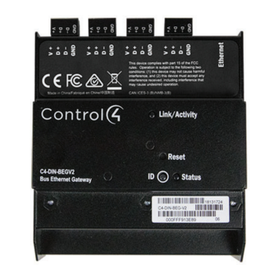
Front view
Figure 1: Front view
1
4
5
1 4 × RS-485 pluggable connectors
2 Link/Activity LED
3 Reset button (recessed)
4 Module ID button
5 Module Status LED
Pre-installation instructions
Before you install in a Control4 panel
1 Use Composer Pro to add the Bus Ethernet Gateway to a project, define its
location in a panel, and print the panel report. See the Composer Pro User
Guide (
ctrl4.co/cpro-ug
) for details.
2 Install the panel following the instructions in the 5-Slot and 2-Slot Panel
Installation Guide (
ctrl4.co/panelinstall
48VDC
1.0W
10/100 Ethernet
One Ethernet, RJ-45
Four RS-485 pluggable terminal blocks
36 AWG to 14 AWG (0.14 mm to 1.5 mm)
32˚F to 104˚F (0˚C to 40˚C)
5% to 95% non-condensing
-4˚F to 158˚F
(-20˚C to 70˚C)
4.28 × 4.48 × 2.15 in.
(108.6 mm × 113.9 mm × 54.6 mm)
6M
1.20 lbs (0.54 kg)
1.55 lbs (0.70 kg)
2
3
).
Advertisement

Related Manuals for Control 4 C4-DIN-BEG-V2


Summary of Contents for Control 4 C4-DIN-BEG-V2
- Page 1 Introduction Figure 1: Front view The Control4® Bus Ethernet Gateway (C4-DIN-BEG-V2) is intended for use in a Control4 system. This device installs in a Control4 Centralized Lighting panel or in any standard DIN rail panel with 35 mm rails. The Bus Ethernet Gateway provides the communication bridge between keypads on the RS-485 bus and the Control4 system.
- Page 2 4 On the top of the Bus Ethernet Gateway, connect the Ethernet Cat5 cable to Before you install in a third-party DIN rail panel the RJ-45 port. 1 Install the third-party panel according to the third-party instructions. 5 Install the other modules in the panel as defined in their respective installation guides.