Table of Contents
Advertisement
Quick Links
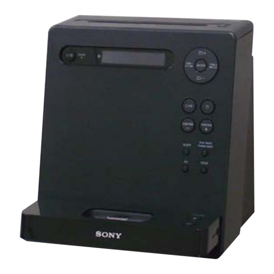
SERVICE MANUAL
Ver. 1.0 2009.02
• HCD-LX20i is the amplifi er, CD player, tuner
and iPod section in CMT-LX20i.
iPod is a trademark of Apple Inc., registered in the U.S.
and other countries.
MPEG Layer-3 audio coding technology and patents
licensed from Fraunhofer IIS and Thomson.
All other trademarks and registered trademarks are of
their respective holders. In this manual,
are not specified.
Main unit
AUDIO POWER SPECIFICATIONS
POWER OUTPUT AND TOTAL HARMONIC DISTORTION:
With 4 ohm loads, both channels driven, from 120
10,000 Hz; rated 25 watts
per channel minimum RMS power, with no more than 10% total harmonic
distortion from 250 milliwatts to rated output.
section
DIN power output (rated):
4 + 4 watts (4 ohms at 1 kHz, DIN)
Continuous RMS power output (reference): 5 + 5 watts (4 ohms at 1 kHz,
10% THD)
Inputs
AUDIO IN (stereo mini jack): Voltage 775 mV, impedance 22 kilohms
Outputs
PHONES (stereo mini jack): accepts headphones with an impedance of
8 ohms or more
SPEAKER: accepts impedance of 4 ohms
CD player section
System: Compact disc and digital audio system
Laser Diode Properties
Emission Duration: Continuous
Laser Output*: Less than 44.6μW
*
objective lens surface on the Optical Pick-up Block with 7mm aperture.
Frequency response: 20 Hz — 20 kHz
Signal-to-noise ratio: More than 90 dB
Dynamic range: More than 90 dB
Tuner section
FM stereo, FM/AM superheterodyne tuner
FM tuner section:
Tuning range:
87.5 — 108.0 MHz (100 kHz step)
Antenna: FM lead antenna
Intermediate frequency: 10.7 MHz
AM tuner section:
Tuning range:
530 —1,710 kHz (10 kHz step)
531 —1,710 kHz (9 kHz step)
Antenna: AM loop antenna
Intermediate frequency: 450 kHz
Sony Corporation
9-889-400-01
2009B05-1
Audio&Video Business Group
©
2009.02
Published by Sony Techno Create Corporation
®
TM
and
marks
SPECIFICATIONS
iPod section
Compatible iPod models:
iPod nano 4th
generation
iPod touch 2nd
generation
iPod nano 3rd
generation
iPod classic
(video)
General
Power requirements: 120 V AC, 60 Hz
Power consumption: 25 watts
Dimensions (w/h/d) (excl. speakers): Approx. 200 × 221 × 205 mm
Mass (excl. speakers): Approx. 2.2 kg
HCD-LX20i
Model Name Using Similar Mechanism
CD Mechanism Type
Base Unit Name
Optical Pick-up Block Name
iPod touch 1st
(video)
generation
iPod nano 2nd
generation
(aluminum)
COMPACT DISC RECEIVER
US Model
Canadian Model
NEW
CDM80BTS-F4BD94-WOD
BU-F4BD94-WOD
KSM-215CFP
iPod nano 1st
iPod 5th
generation
generation
generation
(video)
(color display)
iPod mini
iPod 4th
generation
iPod 4th
Advertisement
Table of Contents

Related Manuals for Sony HCD-LX20i


Summary of Contents for Sony HCD-LX20i
- Page 1 SERVICE MANUAL US Model Canadian Model Ver. 1.0 2009.02 • HCD-LX20i is the amplifi er, CD player, tuner and iPod section in CMT-LX20i. iPod is a trademark of Apple Inc., registered in the U.S. Model Name Using Similar Mechanism and other countries.
- Page 2 LES DIAGRAMMES SCHÉMATIQUES ET LA LISTE DES PIÈCES SONT CRITIQUES POUR LA SÉCURITÉ DE FONC- TIONNEMENT. NE REMPLACER CES COMPOSANTS QUE PAR DES PIÈCES SONY DONT LES NUMÉROS SONT DON- NÉS DANS CE MANUEL OU DANS LES SUPPLÉMENTS PUBLIÉS PAR SONY.
-
Page 3: Table Of Contents
HCD-LX20i TABLE OF CONTENTS SERVICING NOTES ..........GENERAL ..............DISASSEMBLY 3-1. Disassembly Flow ............3-2. Panel (Back), Panel (Front) Block ........3-3. MAIN Board ..............3-4. PANEL Board ..............3-5. CD Mechanism Block (CDM80BTS-F4BD94-WOD) ... 3-6. Belt (MOT) ..............3-7. Base Unit (BU-F4BD94-WOD) ........10 TEST MODE ............ -
Page 4: Servicing Notes
HCD-LX20i SECTION 1 SERVICING NOTES NOTE OF REPLACING THE DRIVER BOARD NOTES ON HANDLING THE OPTICAL PICK-UP When the DRIVER board is damaged, exchange the entire BLOCK OR BASE UNIT CDM80BTS. The laser diode in the optical pick-up block may suffer electrostat-... -
Page 5: General
HCD-LX20i SECTION 2 This section is extracted GENERAL from instruction manual. Getting Started Antennas To adjust the volume Press VOLUME +/— Find a location and an orientation that provide good reception, and then set up the antenna. To connect an optional headphones Keep the antennas away from the speaker cords and the ... - Page 6 remaining playing time for a track. Sony cannot accept responsibility in the event that data recorded to remaining playing time of a current CD-DA disc during normal iPod is lost or damaged when using an iPod with this system.
-
Page 7: Disassembly
HCD-LX20i SECTION 3 DISASSEMBLY • This set can be disassembled in the order shown below. 3-1. DISASSEMBLY FLOW 3-2. PANEL (BACK), PANEL (FRONT) BLOCK (Page 7) 3-3. MAIN BOARD 3-4. PANEL BOARD 3-5. CD MECHANISM BLOCK (Page 8) (Page 8) -
Page 8: Main Board
HCD-LX20i 3-3. MAIN BOARD bracket (HT) screw (BV3 (3-CR)) MAIN board Remove a solder. screw (BV3 (3-CR)) two screws (BVTP3 × 8) screw (BVTP3 × 8) screw (BV3 (3-CR)) connector (CNS002) 3-4. PANEL BOARD Note: This illustration sees the panel (front) block from back side. -
Page 9: Cd Mechanism Block (Cdm80Bts-F4Bd94-Wod)
HCD-LX20i 3-5. CD MECHANISM BLOCK (CDM80BTS-F4BD94-WOD) three screws (BV3 (3-CR)) four screws (BVTP3 × 10) three screws holder (CDM) (BVTP2.6 (3CR)) screw (BV3 (3-CR)) lid (CDM) block CD mechanism block (CDM80BTS-F4BD94-WOD) 3-6. BELT (MOT) belt (MOT) – CD mechanism block bottom view –... -
Page 10: Base Unit (Bu-F4Bd94-Wod)
HCD-LX20i 3-7. BASE UNIT (BU-F4BD94-WOD) vibration proof rubber three floating screws floating screw vibration proof rubber vibration proof rubber tension coil spring (G-1) base unit (BU-F4BD94-WOD) tension coil spring (G-2) vibration proof rubber – CD mechanism block bottom view –... -
Page 11: Test Mode
HCD-LX20i SECTION 4 TEST MODE COLD RESET CD/USB POWER MANAGE The cold reset clears all data including preset data stored in the This mode is for switch the CD/USB power supply on/off. Even if memory to initial conditions. Execute this mode when returning this state pulls out AC plug, it is held. - Page 12 HCD-LX20i CD ERROR CODE The past errors of the optical pick-up system (= optical unit + CD board) are displayed as the BD Errors as shown below. Procedure: 1. Press the [ ] button to turn the power on. 2. Press the [FUNCTION +] button to select CD function.
-
Page 13: Electrical Adjustments
HCD-LX20i SECTION 5 ELECTRICAL ADJUSTMENTS 0 dB=1 μV TUNER SECTION AM VT VOLTAGE CONFIRMATION Frequency Display Reading on Digital Voltmeter [AM] 530 kHz 1.6 ± 0.3 V Setting: 1,710 kHz 8 ± 0.5 V Function: TUNER Band: AM 60 cm... - Page 14 HCD-LX20i FM TUNE LEVEL CHECK Checking Location: – CD Board (Conductor Side) – signal generator Procedure: 1. Turn on the set. 2. Input the following signal from signal generator to FM antenna TP124 (VC) input directly. Carrier frequency : A = 87.5 MHz, B = 98 MHz, C = 108 MHz...
-
Page 15: Diagrams
HCD-LX20i SECTION 6 DIAGRAMS 6-1. BLOCK DIAGRAM - CD, TUNER Section - J802 ANTENNA FM/AM BAND-PASS FM MIX CF801 FILTER 36 FMRF-O FM-MIX 8 FM-IF FM-OUT 22 MPX-IN L-OUT TUNER-L CF805 Q803 R-OUT R-CH L851 AM RF L803 AM TRACKING AM IF •... -
Page 16: Block Diagram - Main Section
HCD-LX20i 6-2. BLOCK DIAGRAM - MAIN Section - POWER R-ch is omitted due to same as L-ch. TUNER-L 4 TU-L SEL-L VOL-L OUT-L J931 R-CH IC301 SIGNAL PATH PHONES SB-L : TUNER (FM/AM) : CD PLAY CD-L 6 CD-L J351... - Page 17 HCD-LX20i THIS NOTE IS COMMON FOR PRINTED WIRING BOARDS AND SCHEMATIC DIAGRAMS. • Circuit Board Location (In addition to this, the necessary note is printed in each block.) CD board For Printed Wiring Boards. For Schematic Diagrams. Note: Note: • X : parts extracted from the component side.
-
Page 18: Printed Wiring Board - Cd Board
HCD-LX20i 6-3. PRINTED WIRING BOARD - CD Board - • See page 17 for Circuit Boards Location. • : Uses unleaded solder. CD BOARD CD BOARD (COMPONENT SIDE) (CONDUCTOR SIDE) (SLED) R165 S201 (LIMIT) C405 R416 C403 C404 C125 R402... -
Page 19: Schematic Diagram - Cd Board
HCD-LX20i 6-4. SCHEMATIC DIAGRAM - CD Board - • See page 17 for Waveforms. • See page 28 for IC Block Diagrams. • See page 29 for IC Pin Function Description. R127 R126 C107 C136 R125 R142 R139 R129 Q301... -
Page 20: Printed Wiring Board - Main Board
HCD-LX20i 6-5. PRINTED WIRING BOARD - MAIN Board - • See page 17 for Circuit Boards Location. • : Uses unleaded solder. • Semiconductor Location Ref. No. Location MAIN BOARD D101 D102 D103 R844 JW810 D104 R847 Q801 R845 D121... -
Page 21: Schematic Diagram - Main Board (1/3)
HCD-LX20i 6-6. SCHEMATIC DIAGRAM - MAIN Board (1/3) - • See page 17 for Waveforms. • See page 28 for IC Block Diagrams. (1/3) MAIN BOARD L851 TRACKING L852 L851 C875 C874 C855 120uH 220uH 100p 220p AM OSC 100p... -
Page 22: Schematic Diagram - Main Board (2/3)
HCD-LX20i 6-7. SCHEMATIC DIAGRAM - MAIN Board (2/3) - • See page 28 for IC Block Diagrams. (2/3) MAIN BOARD MAIN BOARD (1/3) (Page 21) JR882 CNS212 R884 iPod-LCH + R883 iPod-LCH - iPod-RCH + JR881 0 iPod-RCH - C247... -
Page 23: Schematic Diagram - Main Board (3/3)
HCD-LX20i 6-8. SCHEMATIC DIAGRAM - MAIN Board (3/3) - MAIN MAIN (Page 21) (Page 22) MAIN (Page 22) BOARD BOARD BOARD (1/3) (2/3) (2/3) MAIN BOARD (3/3) IC301 POWER AMP IC301 LA4631-E C350 C351 W302 C354 C321 C322 (CHASSIS) 1000... -
Page 24: Printed Wiring Boards - Panel Section
HCD-LX20i 6-9. PRINTED WIRING BOARDS - PANEL Section - • See page 17 for Circuit Boards Location. • : Uses unleaded solder. • Semiconductor Location Ref. No. Location (Page 26) D451 KEY-EJECT D452 BOARD PANEL BOARD D453 CNA938 D454 (NC) -
Page 25: 6-10. Schematic Diagram - Panel Section
HCD-LX20i 6-10. SCHEMATIC DIAGRAM - PANEL Section - • See page 17 for Waveforms. • See page 28 for IC Block Diagrams. • See page 29 for IC Pin Function Description. PANEL BOARD C452 IC453 NJL22H400B R451 IC453 R509 IC B/D... -
Page 26: 6-11. Printed Wiring Boards - Audio In/Out, Key, Power Supply Section
HCD-LX20i 6-11. PRINTED WIRING BOARDS - AUDIO IN/OUT, KEY, POWER SUPPLY Section - • See page 17 for Circuit Boards Location. • : Uses unleaded solder. PT-AC BOARD AU-JACK BOARD HP-JACK BOARD R923 C921 R921 C935 L901 R924 W921 C922... -
Page 27: 6-12. Schematic Diagram - Audio In/Out, Key, Power Supply Section
HCD-LX20i 6-12. SCHEMATIC DIAGRAM - AUDIO IN/OUT, KEY, POWER SUPPLY Section - AU-JACK BOARD HP-JACK BOARD R932 R934 CNA901 CNA921 R921 R923 4.7k C921 470p AUDIO-IN L SP-R J921 L901 AUDIO IN MAIN AUDIO-IN GND PA-R BOARD R931 R933 MAIN... - Page 28 HCD-LX20i • IC Block Diagrams – CD Board – – MAIN Board – IC801 LV23003VA IC201 BD3499FV-E2 IC201 TK63115SCL-G@GT VIN 1 AM RF-IN 36 FM RF-IN THERMAL & 28 FIL OVER CURRENT INPUT INPUT 35 GND2 27 GND PROTECTION GAIN...
- Page 29 HCD-LX20i • IC Pin Function Description CD BOARD IC101 TC94A70FG-006 (D, HZ (CD-MP3 PROCESSOR) Pin No. Pin Name Description AVSS3 Ground terminal RFZI RF ripple zero crossing signal input terminal RFRP RF ripple signal output terminal SBAD Sub beam addition signal output terminal...
- Page 30 HCD-LX20i Pin No. Pin Name Description /LOCK Not used ZDET Zero detection signal output terminal Not used GPIN Not used Micro controller interface mode selection signal input terminal Fixed at "H" in this set DOUT Digital audio data output terminal...
- Page 31 HCD-LX20i PANEL BOARD IC501 MB90F830PF-GE1 (SYSTEM CONTROLLER) Pin No. Pin Name Description O-USBRESET/ DAB +1.2V power supply on/off control signal output terminal Not used DAB1.2V O-POWER Main power on/off control signal output terminal "H": main power on O-AMP-ON Output muting on/off signal output to the power amplifi er O-CD/USM 3.3V ON...
- Page 32 HCD-LX20i Pin No. Pin Name Description 63, 64 SEG0, SEG1 Segment drive signal output to the liquid crystal display Power supply terminal (+3.1V) Ground terminal 67 to 89 SEG2 to SEG24 Segment drive signal output to the liquid crystal display Power supply terminal (+3.1V)
-
Page 33: Exploded Views
HCD-LX20i SECTION 7 EXPLODED VIEWS Note: • -XX and -X mean standardized parts, so • The mechanical parts with no reference The components identifi ed by mark 0 they may have some difference from the number in the exploded views are not sup- or dotted line with mark 0 are critical for original one. -
Page 34: Panel (Front) Section
HCD-LX20i 7-2. PANEL (FRONT) SECTION PANEL board not supplied (KEY-EJECT board) supplied 54 57 D454 LCD451 supplied supplied stage (top) section Ref. No. Part No. Description Remark Ref. No. Part No. Description Remark 3-087-053-01 +BVTP2.6 (3CR) 1-832-619-21 CABLE, FLEXIBLE FLAT (21 CORE) -
Page 35: Stage (Top) Section
HCD-LX20i 7-3. STAGE (TOP) SECTION not supplied (KEY-VOL board) not supplied (IPJ board) not supplied (HP-JACK board) not supplied (AU-JACK board) Ref. No. Part No. Description Remark Ref. No. Part No. Description Remark 3-087-053-01 +BVTP2.6 (3CR) 4-125-090-01 STAGE (TOP 1) -
Page 36: Main Board Section
HCD-LX20i 7-4. MAIN BOARD SECTION CD mechanism section (CDM80BTS-F4BD94-WOD) not supplied not supplied not supplied (FFC GUARD board) not supplied F001 not supplied (PT-AC board) supplied T001 supplied not supplied MAIN board Ref. No. Part No. Description Remark Ref. No. -
Page 37: Cd Mechanism Section (Cdm80Bts-F4Bd94-Wod)
HCD-LX20i 7-5. CD MECHANISM SECTION (CDM80BTS-F4BD94-WOD) not supplied (DRIVER board) not supplied (including DRIVER board) base unit section (BU-F4BD94-WOD) Ref. No. Part No. Description Remark Ref. No. Part No. Description Remark A-1716-736-A CDM80BTS (Including DRIVER board) 2-059-837-01 SPRING (G-1), TENSION COIL... -
Page 38: Base Unit Section (Bu-F4Bd94-Wod)
HCD-LX20i 7-6. BASE UNIT SECTION (BU-F4BD94-WOD) (including sled motor (M402), spindle motor (M401)) spindle motor (M401) sled motor (M402) S201 Ref. No. Part No. Description Remark Ref. No. Part No. Description Remark 0 251 8-820-252-03 OPTICAL PICK-UP BLOCK (KSM-215CFP/C2NP) A-1629-307-A... -
Page 39: Electrical Parts List
HCD-LX20i SECTION 8 AU-JACK ELECTRICAL PARTS LIST Note: • Due to standardization, replacements in • CAPACITORS When indicating parts by reference num- the parts list may be different from the uF: μF ber, please include the board name. parts specifi ed in the diagrams or the com- •... - Page 40 HCD-LX20i DRIVER HP-JACK Ref. No. Part No. Description Remark Ref. No. Part No. Description Remark < CONNECTOR > R205 1-216-809-11 METAL CHIP 1/10W R206 1-216-809-11 METAL CHIP 1/10W CN201 1-784-833-51 CONNECTOR, FFC (LIF (NON-ZIF)) 21P R207 1-216-809-11 METAL CHIP 1/10W...
- Page 41 HCD-LX20i KEY-EJECT KEY-VOL MAIN Ref. No. Part No. Description Remark Ref. No. Part No. Description Remark C953 1-107-826-11 CERAMIC CHIP 0.1uF C162 1-126-923-91 ELECT 220uF C954 1-107-826-11 CERAMIC CHIP 0.1uF C163 1-100-597-91 CERAMIC CHIP 0.1uF C955 1-128-995-21 ELECT CHIP 100uF...
- Page 42 HCD-LX20i MAIN Ref. No. Part No. Description Remark Ref. No. Part No. Description Remark C810 1-165-908-11 CERAMIC CHIP 1uF D171 6-501-817-01 DIODE MA2J1110GLS0 C811 1-165-908-11 CERAMIC CHIP 1uF D191 6-500-334-01 DIODE MC2836-T112-1 C812 1-165-908-11 CERAMIC CHIP 1uF D192 6-500-335-01 DIODE MC2838-T112-1...
- Page 43 HCD-LX20i MAIN Ref. No. Part No. Description Remark Ref. No. Part No. Description Remark Q171 6-550-828-01 RSQ035P03TR R191 1-216-813-11 METAL CHIP 1/10W Q172 8-729-120-28 TRANSISTOR 2SC1623-L5L6 R192 1-216-813-11 METAL CHIP 1/10W Q173 6-551-697-01 TRANSISTOR ISA1235AC1TP-1F R193 1-216-813-11 METAL CHIP 1/10W...
- Page 44 HCD-LX20i MAIN PANEL Ref. No. Part No. Description Remark Ref. No. Part No. Description Remark R824 1-216-825-11 METAL CHIP 2.2K 1/10W C614 1-162-919-11 CERAMIC CHIP 22PF R825 1-216-817-11 METAL CHIP 1/10W C615 1-165-908-11 CERAMIC CHIP 1uF R826 1-216-809-11 METAL CHIP...
- Page 45 HCD-LX20i PANEL PT-AC Ref. No. Part No. Description Remark Ref. No. Part No. Description Remark L660 1-469-981-21 INDUCTOR, FERRITE BEAD R541 1-216-821-11 METAL CHIP 1/10W < LIQUID CRYSTAL DISPLAY > R542 1-216-841-11 METAL CHIP 1/10W R543 1-216-821-11 METAL CHIP 1/10W...
- Page 46 HCD-LX20i PT-AC Ref. No. Part No. Description Remark < FUSE HOLDER > FH001 1-533-217-31 FUSE HOLDER FH002 1-533-217-31 FUSE HOLDER ************************************************************* MISCELLANEOUS ************** 1-832-619-21 CABLE, FLEXIBLE FLAT (21 CORE) 1-832-875-21 CABLE, FLEXIBLE FLAT (21 CORE) 1-836-706-21 CABLE, FLEXIBLE FLAT 0 154...
- Page 47 HCD-LX20i MEMO...
- Page 48 HCD-LX20i REVISION HISTORY Checking the version allows you to jump to the revised page. Also, clicking the version at the top of the revised page allows you to jump to the next revised page. Ver. Date Description of Revision 2009.02...