Advertisement
Quick Links
APPLICATION
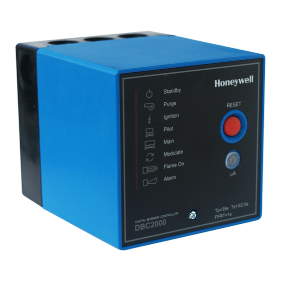
The Honeywell DB2000E is a microprocessor-based
integrated burner control for automatically fired gas,
oil or combination fuel industrial single burner power
burner applications. The DBC2000E system consists
of the relay module and wiring subbase. The
DBC2000E Standard Model provides the minimum
requrements to control an industrial burner system,
such as automatic burner sequencing, flame
supervision, system status indication, system or self-
diagnostics and troubleshooting. The DBC2000E
Enhanced Model includes an integrated Valve
Proofing System, as well as bus communication.
DIGITAL BURNER CONTROLLER
PRODUCT HANDBOOK
The DBC2000E is programmed to provide a level of
safety, functional capability and features beyond the
capacity of conventional controls.
FEATURES
•
Employs a plug-in mounting method
•
Uses a microprocessor to improve performance
•
The progress of the sequence can be easily
determined by status indicator LEDs
•
All models have a 4-wire firing rate switching
circuit to control an air damper or other auxiliary
equipment during startup of the burner.
•
Safe start check before and during pre-purge
•
Safety shutdown occurs on
- malfunction of the burner controller
- failure to ignite the pilot burner or main burner
- loss of flame during run period
- opening of air flow switch during pre-purge,
start-up, run and post-purge period.
- flame signal detection during standby or pre-
purge period
•
Remote communication (Enhanced model only)
•
Valve Proving System (Enhanced model only)
Application ...................................................................1
Features .......................................................................1
Specifications ...............................................................2
Dimensions ..................................................................3
Installation and wiring ...................................................4
Operation .....................................................................8
DBC2000 SERIES
Contents
ENS7003R0 KO06 2010
Advertisement

Related Manuals for Honeywell DBC2000 Series


Summary of Contents for Honeywell DBC2000 Series
-
Page 1: Table Of Contents
- failure to ignite the pilot burner or main burner APPLICATION - loss of flame during run period The Honeywell DB2000E is a microprocessor-based - opening of air flow switch during pre-purge, integrated burner control for automatically fired gas, start-up, run and post-purge period. -
Page 2: Application
SPECIFICATIONS Table 1: Model Selection Guide Description / Application Supply voltage Model DBC2000E1xxx Standard model 115 or 230Vac DBC2000E2xxx Enhanced model 115 or 230Vac The Enhanced Model includes remote bus communication and a Valve Proofing System. Table 2: Sequence timing Waiting Waiting Ignition... -
Page 3: Dimensions
The LEDs will shortly blink as soon as power is applied to Mains input: Supply voltage the DBC2000E and then as soon there is a heat demand , 220 to 240Vac -15% +10% 50/60Hz or indicate the burner sequence. 110 to 120Vac -15% +10% 50/60Hz The LED’s are also used to indicate faults. - Page 4 DIMENSIONS Fig. 1: External Dimensions (in mm) Fig. 2: Mounting dimensions of sub-base and terminal layout...
-
Page 5: Installation And Wiring
INSTALLATION AND WIRING All external timers must be listed or CAUTION componentrecognized by authorities who have proper jurisdiction. INSTALLATION For on-off gas-fired systems, some authorities who have jurisdiction prohibit the wiring of any limit or When Installing this Product… operating contacts in series between the flame safeguard control and the main fuel valve(s). - Page 6 and main valve 2 to Terminal 12 for the VPS function) REMOVE THE RELAY MODULE FROM When using Interrupted Pilot, connect the pilot valve ITS SUB BASE AND FIX THE SUB BASE to Terminal 6. Connect the main valves to Terminal 7 (Enhanced Model: connect main valve 1 to Terminal 7 Loosen the M3 fixing screw as shown in Fig.
- Page 7 Fig. 3-1: Terminal layout Fig. 3-2: Example1 of wiring to external equipment ENS7003R0 KO06 2010...
- Page 8 Fig. 3-3: Example2 of wiring to external equipment Fig. 4: Connection to flame detector ENS7003R0 KO06 2010...
-
Page 9: Operation
OPERATION 1. NORMAL OPERATION Operation of BC2000 and device Indicator LED * Power SW and Controllers The power supply voltage is applied across Terminal 1, and 2. ●○○○○○○○ Power SW ON, When no flame signal is present, the combustion airflow switch is Limit SW OM opened (T14=OFF) and safety lockout circuit is closed (ON), it is possible to start. - Page 10 Limit/Power Switch ON CONTROLLER ON CONTROLLER OFF High Interlock ON Interlock ON BLOWER Ignition Trial Post-Purge IGNITION TR Pilot-Only PILOT VALVE Main Trial MAIN VALVE Main Stabilized ALARM Pre-Purge Modulating HIGH DAMPER Ignition Wait AIR FLOW SW FLAME SIGNAL POWER PRE/POST-PURGE IGNITION TRIAL PILOT ONLY...
- Page 11 2. ERROR TYPES AND SAFE SHUTDOWN If a critical error related to safety operation (such as a loss of flame, opening of the air flow switch during the ignition trial and run sequence) is detected, the DBC2000 instantly goes into lock-out and goes to pre-purge status. If a non critical error (such as opening of the air flow switch opening during post-purge) is detected, DBC2000 holds the sequence for lock-out time and then goes into lock- out.
- Page 12 Flame Lockout Failure BLOWER Post-Purge IGNITION TR PILOT VALVE Error Confirmation MAIN VALVE ALARM 20 SEC HIGH DAMPER AIR FLOW SW FLAME SIGNAL POWER PRE/POST-PURGE IGNITION TRIAL PILOT ONLY M-TRI/M-STA FLAME ALARM Fig. 7: Flame failure during run period Power SW ON Lockout BLOWER IGNITION TR...
- Page 13 Lockout BLOWER Post-Purge IGNITION TR PILOT VALVE MAIN VALVE ALARM 20 SEC HIGH DAMPER Pre-Purge AIR FLOW SW FLAME SIGNAL Error Confirmation POWER PRE/POST-PURGE IGNITION TRIAL PILOT ONLY M-TRI/M-STA FLAME ALARM Fig. 9: When false flame is generated during pre-purge Lockout BLOWER IGNITION TR...
- Page 14 Pre-Purge restart BLOWER IGNITION TR PILOT VALVE MAIN VALVE ALARM Lockout Timing HIGH DAMPER Pre-Purge Pre-Purge AIR FLOW SW FLAME SIGNAL Error Confirmation POWER PRE/POST-PURGE IGNITION TRIAL PILOT ONLY M-TRI/M-STA FLAME ALARM Fig. 11: When air flow switch goes OFF during pre-purge, and then ON again within Lockout timing CONTROLLER OFF Lockout BLOWER...
- Page 15 Air flow SW OFF Lockout BLOWER PostPurge IGNITION TR PILOT VALVE MAIN VALVE ALARM 20 SEC HIGH DAMPER AIR FLOW SW FLAME SIGNAL Error Confirmation POWER PRE/POST-PURGE IGNITION TRIAL PILOT ONLY M-TRI/M-STA FLAME ALARM Fig. 13: When air flow switch goes OFF during Pilot stabilization Table 5: Error condition and LED status Indicator LED status Sequence...
- Page 16 Flame signal is present ●◐○○○○◐◐ Ignition Trial Air flow switch goes OFF ●◐◐○○○○◐ Ignition failure (flame signal is present during ignition-trial). ●○◐○○○○◐ Pilot Air flow switch goes OFF ●◐○◐○○○◐ No flame signal ●○○◐○○◐◐ Main ignition Trial Air flow switch goes OFF ●◐○○◐○○◐...
- Page 17 ENS7003R0 KO06 2010...
- Page 18 ENS7003R0 KO06 2010...
- Page 19 ENS7003R0 KO06 2010...
- Page 20 ENS7003R0 KO06 2010...