SMC ISE70, ISE71 - High Precision Digital Pressure Switch Manual
- Manual (13 pages) ,
- User manual (1 page) ,
- Operation manuals (88 pages)
Advertisement
- 1 Safety Instructions
- 2 Specifications
- 3 Names of Individual parts
- 4 Installation
- 5 Setting (Measurement mode)
- 6 Pressure Setting
- 7 3 Step Setting mode
- 8 Simple Setting mode
- 9 Function Selection mode
- 10 Other Settings
- 11 Maintenance
- 12 Troubleshooting
- 13 Limitations of Use
- 14 Product Disposal
- 15 Contacts
- 16 Documents / Resources
The intended use of the pressure switch is to measure and display the pressure of fluid and to provide an output signal.
Safety Instructions
These safety instructions are intended to prevent hazardous situations and/or equipment damage. These instructions indicate the level of potential hazard with the labels of "Caution," "Warning" or "Danger."
They are all important notes for safety and must be followed in addition to International Standards (ISO/IEC) *1), and other safety regulations.
*1) ISO 4414: Pneumatic fluid power - General rules relating to systems.
ISO 4413: Hydraulic fluid power - General rules relating to systems.
IEC 60204-1: Safety of machinery - Electrical equipment of machines. (Part 1: General requirements)
ISO 10218-1: Manipulating industrial robots -Safety. etc.
- Refer to product catalogue, Operation Manual and Handling Precautions for SMC Products for additional information.
- Keep this manual in a safe place for future reference.
 | Caution indicates a hazard with a low level of risk which, if not avoided, could result in minor or moderate injury. |
 | Warning indicates a hazard with a medium level of risk which, if not avoided, could result in death or serious injury. |
 | Danger indicates a hazard with a high level of risk which, if not avoided, will result in death or serious injury. |
- Always ensure compliance with relevant safety laws and standards.
- All work must be carried out in a safe manner by a qualified person in compliance with applicable national regulations.
- This product is class A equipment intended for use in an industrial environment. There may be potential difficulties in ensuring electromagnetic compatibility in other environments due to conducted or radiated disturbances.
Otherwise electric shock, malfunction or product damage can result. - Refer to the operation manual on the SMC website (URL: https://www.smcworld.com) for more safety instructions.
Specifications
General specifications

IO-Link specifications

Special products (-X) might have specifications different from those shown in this section. Contact SMC for specific drawings.
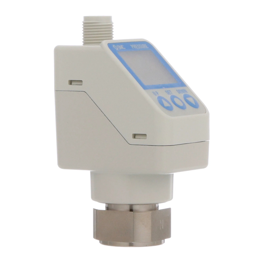
Names of Individual parts
Product

Display

| Part | Description |
| Operation Light | Displays the switch operating condition |
| Main display | Displays pressure measurement values and error codes (2 colour display). |
| Sub display (left) | Displays items (Orange) |
| Sub display (right) | Displays set values, peak and bottom values. (Orange) |
| UP button | Increases mode and ON/OFF set values. |
| DOWN button | Decreases mode and ON/OFF set values. |
| SET button | Changes the mode and confirms the settings. |
| IO-Link status indicator light | Displays OUT1 output communication status (SIO mode, start-up mode, operation mode) and the presence of communication data. |
Installation
Installation
- Do not install the product unless the safety instructions have been read and understood.
Environment
- Do not install in a location subject to vibration or impact in excess of the product's specifications.
- Do not mount in a location exposed to radiant heat that would result in temperatures in excess of the product specification.
Mounting with Bracket
Mount the bracket to the product using mounting screws supplied (M4x6 L (2 pcs)) then set the product in the required position.
Tighten the bracket mounting screws to a torque of 0.76 ±0.1 N•m.

Piping
- Before connecting piping make sure to clean up chips, cutting oil, dust.
- After hand tightening, tighten the fitting using a spanner on the flat surfaces of the fitting (24 mm A/F).
- When tightening, do not hold the upper part of the product (display) with the spanner.
- For Rc1/4 and NPT1/4 threads the tightening torque must be 8 to 12 N•m. For G1/4 thread the tightening torque must be 4 to 5 N•m.

Display Rotation
- During installation, the upper part (display) of the product can be rotated by 336°. Take care as rotating the display with excessive force will damage the end stopper.
![]()

Wiring
- Connections should be made with the power supply turned off.
- Use a separate route for the product wiring and any power or high voltage wiring. Otherwise, malfunction may result due to noise.
- If a commercially available switching power supply is used, be sure to ground the frame ground (FG) terminal. If a switching power supply is connected, noise will be superimposed and will not meet the product specifications.
Insert a noise filter such as a line noise filter/ferrite between the switching power supplies or change the switching power supply to the series power supply.
How to use connector
Align the cable connector key groove with the product connector key to insert and rotate the knurled part of the connector.
Connect the wires of the lead wire to the M12 connector as shown below.
M12 Connector (Port class A)
- When used as a switch output device
![]()
No. Name Colour Function 1 DC(+) Brown 12 to 24 VDC 2 OUT2 White Switch output 2 3 DC(-) Blue 0 V 4 OUT1 Black Switch output 1 - When used as an IO-Link device
![]()
No. Name Colour Function 1 L+ Brown 18 to 30 VDC 2 DO White Switch output 2 3 L- Blue 0 V 4 C/Q Black Communication data (IO-Link) / Switch output 1 (SIO)


Setting (Measurement mode)

Pressure Setting
Default settings
When the pressure exceeds the set value, the switch will be turned ON.
When the pressure falls below the set value by the amount of hysteresis or more, the switch will be turned OFF.
The default setting is to turn ON the pressure switch when the pressure reaches the centre of the atmospheric pressure and upper limit of the rated pressure range. If this condition is acceptable, then keep these settings.

Default setting for Pressure range
| Item | ISE70 | ISE71 |
| [P_1] Set value of OUT1 [MPa] | 0.500 | 0.800 |
| [H_1] Hysteresis of OUT1 [MPa] | 0.050 | 0.080 |
3 Step Setting mode
3 step setting mode (hysteresis mode)
In 3 step setting mode, the set value (P_1 or n_1) and hysteresis (H_1) can be changed. Set the items on the sub display (set value or hysteresis) using the UP and DOWN button. When changing the set value, follow the operation below. The hysteresis setting can be changed in the same way.
- Press the SET button once when the item to be changed is shown on the sub display. The set value on the sub display will start flashing.

- Press the UP or DOWN button to change the set value.
When the UP and DOWN buttons are pressed and held simultaneously for 1 second or longer, the set value is displayed as [- - -], and the set value will be the same as the current pressure value automatically (snap shot function).
Afterwards, it is possible to adjust the value by pressing the UP or DOWN button. - Press the SET button to complete the setting.

The Pressure switch turns on within a set pressure range (from P1L to P1H) during window comparator mode. Set P1L, the lower limit of the switch operation, and P1H, the upper limit of the switch operation and WH1 (hysteresis) following the instructions given above.
(When reversed output is selected, the sub display (left) will indicate [n1L] and [n1H].)
- Set OUT2 in the same way.
- Setting of the normal/reverse output switching and hysteresis/window comparator mode switching are performed using the function selection mode [F 1] OUT1 setting and [F 2] OUT2 setting.
Simple Setting mode
- Press and hold the SET button between 1 and 3 seconds in measurement mode. [SEt] is displayed on the main display. When the button is released while in the [SEt] display, the current pressure value is displayed on the main display, [P_1] or [n_1] is displayed on the sub display (left), and the set value is displayed on the sub display (right) (Flashing).
- Change the set value using the UP and DOWN button, and press the SET button to set the value. Then, the setting moves to hysteresis setting. (The snap shot function can be used).
![]()
- Change the set value with the UP or DOWN button, and press the SET button to set the value. Then, the setting moves to the delay time of the switch output. (The snap shot function can be used).
- The delay time of the switch output can be selected by pressing the UP or DOWN button at the ON and OFF point of the switch output. Delay time setting can prevent the output from chattering.
The delay time can be set in the range 0.00 to 60.00 sec. in 0.01 sec. increments. - Press the SET button for less than 2 seconds to complete the OUT1 setting. [P_2] or [n_2] is displayed on the sub screen (left). Continue with setting OUT2.
Press and hold the SET button for 2 seconds or longer to complete the setting. The product will return to measurement mode.

- In window comparator mode, set P1L, the lower limit of the switch operation, and P1H, the upper limit of the switch operation, WH1 (hysteresis) and dtH / dtL (delay time) following the instructions given above. (when reversed output is selected, the sub display (left) will indicate [n1L] and [n1H]).
- Set OUT2 in the same way.
Function Selection mode
In measurement mode, press the SET button between 3 and 5 seconds to display [F 0]. Select to display the function to be changed [F□□]. Press and hold the SET button for 2 seconds or longer in function selection mode to return to measurement mode.

∗: Some products do not have all of the functions. If a function is not available or selected due to configuration of other functions, [- - -] is displayed on the sub display.
Other Settings
- Peak / Bottom value display
- Snap Shot function
- Zero-clear function
- Key Lock function
Refer to the operation manual on the SMC website (URL: https://www.smcworld.com) for further details of how to set these and other functions.
Maintenance
General Maintenance
- Not following proper maintenance procedures could cause the product to malfunction and lead to equipment damage.
- If handled improperly, compressed air can be dangerous.
- Maintenance of pneumatic systems should be performed only by qualified personnel.
- Before performing maintenance, turn off the power supply and be sure to cut off the supply pressure. Confirm that the air is released to atmosphere.
- After installation and maintenance, apply operating pressure and power to the equipment and perform appropriate functional and leakage tests to make sure the equipment is installed correctly.
How to reset the product after power cut or forcible de-energizing
The setting of the product will be retained as it was before a power cut or de-energizing. The output condition is also basically recovered to that before a power cut or de-energizing, but may change depending on the operating environment.
Therefore, check the safety of the whole installation before operating the product. If the installation is using accurate control, wait until the product has warmed up (approximately 10 to 15 minutes).
Troubleshooting
Error Indication
| Error | Error displayed | Description | Measures |
| Over current error |  | The load current applied to the switch output has exceeded the maximum value. | Turn the power off and remove the cause of the over current. Then supply the power again. |
| Residual pressure error |  | During zero clear operation, pressure greater than ±7% F.S. is present. Note that the mode is returned to measurement mode automatically 1 s later. The zero clear range varies by ±1% F.S. due to variation between individual products. | Release the applied pressure to atmosphere, and retry the zero clear operation. |
| Pressurize error |  | Pressure exceeding the upper limit of the set pressure range is applied. | Reset applied pressure to a level within the set pressure range. |
 | Pressure exceeding the lower limit of the set pressure range is applied. | ||
| System error |  | Displayed if an internal data error has occurred. | Turn the power off and on again. If the failure cannot be solved, contact SMC. |
| Version does not match |  | Version of master and IO-Link does not match. | Align the master IO-Link version to the device. |
If the error cannot be reset after the above measures are taken, or errors other than the above are displayed, please contact SMC.
Limitations of Use
Limited warranty and Disclaimer/Compliance Requirements
Refer to Handling Precautions for SMC Products.
Product Disposal
This product shall not be disposed of as municipal waste. Check your local regulations and guidelines to dispose this product correctly, in order to reduce the impact on human health and the environment.
Contacts
Refer to www.smcworld.com or www.smc.eu for your local distributor / importer.
SMC Corporation
URL: https://www.smcworld.com (Global) https://www.smc.eu (Europe)
SMC Corporation, 4-14-1, Sotokanda, Chiyoda-ku, Tokyo 101-0021, Japan
Specifications are subject to change without prior notice from the manufacturer.
© 2021 SMC Corporation All Rights Reserved.
Template DKP50047-F-085M

Documents / Resources
References
Download manual
Here you can download full pdf version of manual, it may contain additional safety instructions, warranty information, FCC rules, etc.
Download SMC ISE70, ISE71 - High Precision Digital Pressure Switch Manual
Advertisement
Thank you! Your question has been received!


Need Assistance?
Do you have a question about the ISE70 that isn't answered in the manual? Leave your question here.