U-Line U-29RB-13A User Manual & Service Manual
Hide thumbs
Also See for U-29RB-13A:
- User manual & service manual (48 pages) ,
- Quick start manual (17 pages) ,
- User manual & service manual (5 pages)
Table of Contents
Advertisement
Quick Links
Advertisement
Table of Contents
Troubleshooting

Related Manuals for U-Line U-29RB-13A


Summary of Contents for U-Line U-29RB-13A
- Page 1 USER GUIDE & SERVICE MANUAL Model: U-29RB-13A...
- Page 2 USER GUIDE & SERVICE MANUAL Click on any section below to jump directly there Table of Contents Intro Warranty Claims Parts Safety Ordering Replacement Parts Safety and Warning R600a Specifications Disposal And Recycling System Diagnosis Guide Compressor Specifications Installation Troubleshooting Extended Environmental Requirements Defrost Electrical...
-
Page 3: Product Information
U-Line Customer Care must be contacted immediately at +1.414.354.0300. Service or repairs performed on the unit without prior written approval from U-Line is not permitted. If the unit has been altered or repaired in the field without prior written approval from U-Line, claims will not be eligible. -
Page 4: Safety And Warning
USER GUIDE Safety and Warning DANGER NOTICE This unit contains R600a (Isobutane) which is a Please read all instructions before installing, flammable hydrocarbon. It is safe for regular operating, or servicing the appliance. use. Do not use sharp objects to expedite defrosting. -
Page 5: Disposal And Recycling
USER GUIDE Disposal and Recycling DANGER RISK OF CHILD ENTRAPMENT. Before you throw away your old refrigerator or freezer, take off the doors and leave shelves in place so children may not easily climb inside. If the unit is being removed from service for disposal, check and obey all federal, state, and local regulations regarding the disposal and recycling of refrigeration appliances, and follow these steps completely:... -
Page 6: Environmental Requirements
USER GUIDE Environmental Requirements This model is intended for indoor/interior applications only and is not to be used in installations that are open/ exposed to natural elements. This unit is designed to operate between 50°F (10°C) and 100°F (38°C). Higher ambient temperatures may reduce the unit’s ability to reach low temperatures and/or reduce ice production on applicable models. - Page 7 USER GUIDE Electrical WARNING SHOCK HAZARD — Electrical Grounding Required. Never attempt to repair or perform maintenance on the unit until the electricity has been disconnected. Never remove the round grounding prong from the plug and never use a two-prong grounding adapter.
-
Page 8: Cutout Dimensions
USER GUIDE Cutout Dimensions PREPARE SITE Your U-Line product has been designed for either free- standing or built-in installation. When built-in, your unit does not require additional air space for top, sides, or rear. However, the front grille must NOT be obstructed, and clearance is required for an electrical connection in the rear. -
Page 9: Product Dimensions
USER GUIDE Product Dimensions 23" (584 mm) 1/2" (724 mm) 9/16" (116 mm) 7/8" (530 mm) Product Dimensions... -
Page 10: Side-By-Side Installation
USER GUIDE Side-by-Side Installation 3. Place bracket over holes and attach to unit with two screws removed in step 2 using a T-25 Torx driver. Two units may be installed side-by-side. Tighten screws fully. Cutout width for a side-by-side installation is the cutout 4. -
Page 11: General Installation
USER GUIDE General Installation INSTALLATION 1. Plug in the power/electrical cord. LEVELING INFORMATION 2. Gently push the unit into position. Be careful not to NOTICE entangle the cord. Because these units do not have leveling legs, it is extremely important that they sit on a level surface. -
Page 12: Grille Installation
USER GUIDE Grille Installation REMOVING AND INSTALLING GRILLE WARNING Disconnect electric power to the unit before removing the grille. When using the unit, the grille must be installed. WARNING DO NOT touch the condenser fins. The condenser fins are SHARP and can be easily damaged. Removing the grille 1. -
Page 13: Door Swing
USER GUIDE Door Swing Wall 2-1/8" Min. (54 mm) 90° Door Swing Units have a zero clearance for the door to open 90°, when installed adjacent to cabinets. Stainless Steel models require 2-1/8" (54 mm) door clearance to accommodate the handle if installed next to a wall. -
Page 14: Door Alignment And Adjustment
USER GUIDE Door Adjustments Remove arrow clips: With a puddy knife or other flat tool, gently pry each DOOR ALIGNMENT AND ADJUSTMENT arrow clip from hinge mounting holes. Align and adjust the door if it is not level or is not sealing Set aside arrow clips to be reused on the opposite properly. - Page 15 USER GUIDE Remove bottom hinge: Remove bottom hinge from cabinet using a 1/4” socket. Remove corresponding screws on opposite side of cabinet. On some models there may be a nut behind one or both screws on either side. Install bottom hinge: Install two or three screws, depending on model.
-
Page 16: First Use
USER GUIDE First Use All U-Line controls are preset at the factory. Initial startup requires no adjustments. NOTICE U-Line recommends allowing the unit to run overnight before loading with product. U-Line recommends discarding the ice produced during the first two or three hours of operation to avoid possible dirt or scale that may dislodge from the water line. -
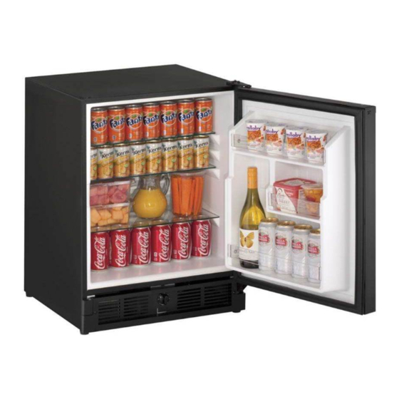
Page 17: Airflow And Product Loading
⁄ ” ⁄ ” (66 mm) (64mm) When determining capacities U-Line uses typical 12 oz. cans, 12 oz. bottles, 750 mL white wine and red wine bottles shown below. ⁄ ” ⁄ ”... -
Page 18: Removing And Installing Interior Shelves
USER GUIDE Interior Shelves NOTICE Make sure the shelves are inserted fully into the REMOVING AND INSTALLING INTERIOR unit. SHELVES The edge strip toward the rear prevents cans and bottles from freezing against the cold evaporator. For models equipped with glass shelves having recessed shelf supports, remove the shelves as follows: 1. -
Page 19: Exterior Cleaning
USER GUIDE Cleaning If any surface discoloring or rusting appears, clean it ® ® quickly with Bon-Ami or Barkeepers Friend Cleanser EXTERIOR CLEANING and a nonabrasive cloth. Always clean with the grain. ® Always finish with Claire Stainless Steel Polish and Vinyl Clad (Black or White) Cleaner or comparable product to prevent further Clean surfaces with a mild detergent and warm water... - Page 20 USER GUIDE High ambient temperature and excessive humidity can also produce frost. CAUTION DO NOT use an ice pick or other sharp instrument to help speed up defrosting. These instruments can puncture the inner lining or damage the cooling unit. DO NOT use any type of heater to defrost.
-
Page 21: Cleaning Condenser
USER GUIDE USER GUIDE u-line.com SAFETY • INSTALLATION & INTEGRATION • OPERATING INSTRUCTIONS • MAINTENANCE • SERVICE Cleaning Condenser INTERVAL - EVERY SIX MONTHS To maintain operational efficiency, keep the front grille free of dust and lint, and clean the condenser when necessary. -
Page 22: Extended Non-Use
If the unit will be exposed to temperatures of 40 F (5 C) or less, the steps above must be followed. For questions regarding winterization, please call U-Line at 414.354.0300. CAUTION Damage caused by freezing temperatures is not covered by the warranty. Extended Non-Use... -
Page 23: Before Calling For Service
BEFORE CALLING FOR SERVICE • Condenser Fan: Air moving through a condenser may be heard. If you think your U-Line product is malfunctioning, read the CONTROL OPERATION section to clearly understand the • Automatic Defrost Drain Pan: Water may be heard function of the control. -
Page 24: Checking Product Temperature
USER GUIDE CHECKING PRODUCT TEMPERATURE Causes which affect the internal temperatures of the cabinet include: • Temperature setting. • Ambient temperature where installed. • Installation in direct sunlight or near a heat source. • The number of door openings and the time the door is open. -
Page 25: Wire Diagram
USER GUIDE Wire Diagram Wire Diagram... -
Page 26: Product Liability
The part that caused the damage must be returned to U-Line in its entirety. The part must be clearly labeled with the serial number of the unit it was removed from, the date, and the servicer who removed the part. -
Page 27: Warranty Claims
Claims must be submitted online at • Final billing - Remodel www.U-LineService.com Warranty parts will be shipped at no charge after U-Line • 60 day submittal deadline from date of completed confirms warranty status. Please provide the model, serial service number, part number and part description. - Page 28 USER GUIDE Parts Parts U-29RB-13A Item Description U-Line P/N Back panel 80-54505-00 Bottle retainer assembly, long 80-54530-00 Bottle retainer assembly, short 80-54533-00 Compressor electricals only 80-54149-00 Compressor w/electricals 80-54150-00 Condenser assembly 80-54521-00 Condenser fan w/screws 80-54014-00 Control assembly 80-54192-00 Control knob...
-
Page 29: Ordering Replacement Parts
Warranty parts will be shipped at no charge after U-Line confirms warranty status. Please provide the model, serial number, part number and part description. Some parts will require color or voltage information. - Page 30 Never use a torch on a fully charged refrigeration system. Never substitute U-Line OEM replacement parts or methods of construction. R-600a must be stored and transported in Technician must observe all federal, state and local laws regarding refrigerants.
- Page 31 USER GUIDE USER GUIDE u-line.com SAFETY • INSTALLATION & INTEGRATION • OPERATING INSTRUCTIONS • MAINTENANCE • SERVICE R-600A SPECIFICATIONS/LABELING WARNING R-600a equipped products are labeled (both the unit and the compressor). Only skilled and well trained service technicians permitted to service R-600a equipped products.
-
Page 32: Leak Detection
USER GUIDE USER GUIDE u-line.com SAFETY • INSTALLATION & INTEGRATION • OPERATING INSTRUCTIONS • MAINTENANCE • SERVICE Evacuate/reclaim via the piecing pliers to ensure the When re-brazing, the system must be purged with dry system is empty of R-600a before any system work is nitrogen and at least one access point open to the performed. - Page 33 USER GUIDE USER GUIDE u-line.com SAFETY • INSTALLATION & INTEGRATION • OPERATING INSTRUCTIONS • MAINTENANCE • SERVICE The low side of the refrigeration system (evaporator, Proper ventilation during service is required. compressor and suction line) must be leak tested with the compressor off (equalized pressure).
-
Page 34: System Diagnosis Guide
USER GUIDE System Diagnosis Guide REGRIGERATION SYSTEM DIAGNOSIS GUIDE System Suction Suction Compressor Condenser Capillary Evaporator Wattage Condition Pressure Line Discharge Tube Normal Normal Slightly Very hot Very hot Warm Cold Normal below room temperature Overcharge Higher than Very cold Slightly warm Hot to warm Cool... -
Page 35: Compressor Specifications
USER GUIDE Compressor Specifications DANGER EM2C46CLC-115V REFRIGERANT R600a VOLTAGE 115V – 127V Electrocution can cause death or serious injury. FREQUENCY 50Hz Burns from hot or cold surfaces can cause serious START WINDING 5.20 +/- 8% Q at 25 °C (77°F) injury. -
Page 36: Troubleshooting - Extended
USER GUIDE Troubleshooting - Extended SPECIFIC ERRORS & ISSUES CAUTION Never attempt to repair or perform maintenance on the unit until the main electrical power has been disconnected from the unit. TROUBLESHOOTING GUIDE Concern Potential Causes Suggested Remedy Not Cooling Compressor overheating Verify proper air flow through condenser. -
Page 37: Ice Maker Diagnosis Flow Chart
USER GUIDE ICE MAKER DIAGNOSIS FLOW CHART DOES THE UNIT REFRIGERATE? Sealed System Leak Low Voltage Electrical Failure Voltage Drop Compressor Failure Wiring Fan Motor Failure Defrost System Failure DOES THE UNIT HARVEST ICE IF THE EJECTOR BLADES ARE MOVED BY HAND OR WITH A WRENCH ? Temperature Control Failure Water Adjustment... -
Page 38: Product Temperature
USER GUIDE PRODUCT TEMPERATURE • Condenser Fan: Air moving through a condenser may be heard. Causes which affect the internal temperatures of the cabinet include: • Temperature setting. • Automatic Defrost Drain Pan: Water may be heard dripping or running into the drain pan when the unit is in the defrost cycle. -
Page 39: Refrigeration System Diagnosis Guide
USER GUIDE REFRIGERATION SYSTEM DIAGNOSIS GUIDE System Suction Suction Compressor Condenser Capillary Evaporator Wattage Condition Pressure Line Discharge Tube Normal Normal Slightly below Very hot Very hot Warm Cold Normal room temperature Overcharge Higher than Very cold - Slightly warm Hot to warm Cool Cold... - Page 40 USER GUIDE Harvest-1 Cycle If bin arm is down, power goes through bin arm switch to Temperature control terminals 2 and 3 are open - 2 and 1 close. the ice maker motor. If bin arm is up, the ice maker will not harvest.
- Page 41 USER GUIDE Harvest-2 Cycle Ice maker ejector blades reach approximately 2:00 Ejector blades stall on ice and ice maker motor pulsates position and cam depresses the hold switch. Power goes until mold heater warms and ice releases. through the hold switch to the ice maker motor and mold heater.
- Page 42 USER GUIDE Water Fill Cycle Ice maker ejector blades reach approximately 10:00 position and cam depresses the water fill switch. Power to the water valve. Ice maker mold fills. WATER FILL CYCLE black black black SWITCH ground MOTOR brown WATER VALVE white COMP.
- Page 43 USER GUIDE TEMPERATURE CONTROL SPECIFICATIONS These temperature controls are double throw, single pole controls. The sensing tube is inserted into the ice maker mold and senses mold temperature. After ice is sensed in the mold, the 2-3 contacts open (stopping the compressor) and the 2-1 contacts are closed (starting the ice maker motor).
-
Page 44: Limit Switch Specifications
USER GUIDE LIMIT SWITCH SPECIFICATIONS The function of this switch is to open in the event of an overheating condition. This bi-metal thermostat is Normally closed Bi-metal switch normally closed and does not initiate the ice harvest cycle. The ice harvest cycle is initiated by a double throw, Open temperature: 104°F single pole temperature located remotely from the ice maker assembly. - Page 45 USER GUIDE FROST FREE REFRIGERATION Defrost Mode Bypass solenoid valve open. Cooling Mode Bypass solenoid closed. Refrigerant flows through bypass system. Evaporator fan operating. Vapor flows from condenser to evaporator without a phase change. Refrigerant flows through capillary tubes. Drain heater on (U-CO29F only). Normal vapor/compression cycle refrigeration.
- Page 46 USER GUIDE Air flow in at evaporator blade Air passes though fin tube evaporator Air flow out at evaporator outlet Condensate drains down past the evaporator, into drain pan, and into condensate pan through drain hose. The drain trough is warmed during defrost by contact with evaporator fins.
- Page 47 USER GUIDE Defrost These units are automatic (cycle) defrost unit will defrost itself when the control/sensor is satisfied of internal temperatures. Defrost mode ends when control/sensor asks for cooling. Defrost 1...
- Page 48 For products installed and used for normal residential use, material cosmetic defects are included in this warranty, with coverage limited to 60 days from the date of original purchase. All service provided by U-Line under the above warranty must be performed by a U-Line factory authorized servicer, unless otherwise specified by U-Line.