Advertisement
- 1 Introduction
- 2 Product Compliance
- 3 Safety Information
- 4 Operation
- 5 Terminals description
-
6
Wiring diagrams
- 6.1 Solution for situations when wires are not available
- 6.2 Solution when wires between thermostat and a wired wiring centre are not available
- 6.3 Solution when there is no enough wires between thermostat and a wired wiring centre
- 6.4 Wireless switching the circulation pump via light switch
- 6.5 Wireless connection of the wiring centre and circulation pump
- 7 Pairing devices
- 8 Housing assembly
- 9 Technical Data
- 10 Documents / Resources
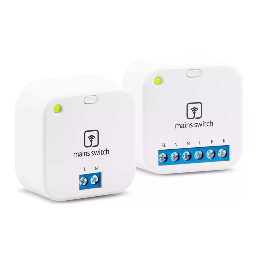
Introduction
RR868 (Mains Switch) is used for electric devices wireless switching e.g. pumps, fans, lighting etc. It is excellent solution in the absence of wiring. The set comes with transmitter, receiver and a surface-mounted enclosures. Transmitter and the receiver can be optionally mounted in a 60 mm can. The RR868 set can also be used for wireless work/failure reports of electrical devices in automation.
 Note: Devices are already paired!
Product Compliance
Directive 2014/30/EU, 2014,35/EU, 2014/53/EU and 2011/65/EU.
 868.0 MHz - 868.6 MHz; <13dBm
Full information is available on the website www.saluslegal.com
Safety Information
Use in accordance with the EU and national regulations. For indoor use only. Keep your device completely dry. This product must be installed by a competent person and in accordance with all the EU and national regulations. Incorrect installation can lead to health or life danger. The device must be disconnected from power supply before removing the housing. During installation, device should be disconnected from 230V power supply!
Operation
Receiver should be connected to the 230 V AC power supply. Diode will turn red and since then receiver is waiting for signal from transmitter.
When the transmitter is powered by 230 V AC it will send immediately signal to the receiver. Receiver will send 230V AC voltage through the SL output. The correct operation of devices is indicated by the green LED diode of the transmitter and receiver. Signal sent by the transmitter is repeated every 5 seconds.
The transmitter has a built-in supercapacitor for back-up power. "Turn Off" command is send 2 times every 5 seconds after power off.
 The transmitter and receiver can be powered from different power lines.
Terminals description

| Terminal | Description |
| L, N | 230 V AC power supply |
| E | Earth Ground |
| SL | 230 V output |
Wiring diagrams
Solution for situations when wires are not available
Connect the transmitter together with the S1 external switch as shown in the diagram below. Receiver should be connected to the 230V AC power supply - "L" and "N" contacts. Electrical device which have to be controlled (e.g. pump, valve, bulb) connect to the receiver - "SL" and "N" contacts. Closing the "S1" switch turns ON transmitter which will send signal to the receiver - connected electrical device will turn ON. Opening the "S1" switch turns OFF transmitter and the receiver goes back to the starting position (connected electrical device will turn OFF).

When S1 transmitter contact is closed, receiver sends 230V AC (SL output).
Solution when wires between thermostat and a wired wiring centre are not available
Connect the transmitter to the thermostat as shown in the diagram below. Connect the "SL" output contact of the thermostat to the "L" input contact of the transmitter.
"N" contacts of the thermostat and transmitter should be wired together. Connect thermostat to the 230V AC power supply.
Receiver should be connected to the wired wiring centre - contacts "L", "N" and "SL" according to the wiring diagram below.
Wiring centre should be connected to the 230V power supply.
Operation of the thermostat (heating signal) turns ON the transmitter, which sends signal to the receiver. The receiver gives 230V voltage on the "SL" contact in the wiring centre. When thermostat stops sending heating signal, then transmitter turns OFF and the receiver goes back to the starting position.

Solution when there is no enough wires between thermostat and a wired wiring centre
Connect the transmitter to the thermostat as shown in the diagram below. Connect the "SL" output contact of the thermostat to the "L" input contact of the transmitter.
"N" contacts of the thermostat and transmitter should be wired together. Connect thermostat to the 230V AC power supply.
Receiver should be connected to the wired wiring centre - contacts "L", "N" and "SL" according to the wiring diagram below.
Wiring centre should be connected to the 230V power supply. Operation of the thermostat (heating signal) turns ON the transmitter, which sends signal to the receiver. The receiver gives 230V voltage on the "SL" contact in the wiring centre. When thermostat stops sending heating signal, then transmitter turns OFF and the receiver goes back to the starting position.

Wireless switching the circulation pump via light switch
The transmitter should be connected in parallel to the lighting (bulb) according to the wiring diagram below. Connect the circulating pump to the receiver - "SL" and "N" contacts.
Connect receiver to the 230V power supply - "L" and "N" contacts. Turning ON the lighting turns ON the transmitter and sends signal to the receiver. The receiver gives 230V voltage on the "SL" contact and the circulating pump is turning ON. Turning OFF the lighting turns OFF the transmitter. Receiver goes back to the starting position and circulation pump is turning OFF.

Wireless connection of the wiring centre and circulation pump
Connect the transmitter and pump relay of the wiring centre according to wiring diagram below. Connect pump to the receiver - "SL" and "N" contacts.
Connect receiver to 230V power supply - "L" and "N" contacts.
Turning ON the pump relay in the wiring centre will activate the transmitter which will send a signal to the receiver. The receiver will turn ON a pump.
Turning OFF the pump relay of the wiring centre turns OFF the transmitter.
Receiver goes back to the starting position and pump is turning OFF.

Pairing devices
Note: Devices are already paired!
- Connect the receiver and the transmitter to 230V AC power supply. Press the button 3 times (very quickly, within 1 second).
- The transmitter stays in the pairing mode for one minute (LED diode flashes orange). Receiver confirms pairing through green LED diode, then diode turns red.

- LED diodes will flash orange on both devices.

- The transmitter stays in the pairing mode for one minute (LED diode flashes orange). Receiver confirms pairing through green LED diode, then diode turns red.

- When the transmitter exits the pairing mode, it sends a signal to the receiver. LED diodes on both devices are green now. The devices are ready for work.


Housing assembly
RR868 includes 2 housing cases - for the receiver and for the transmitter. Devices assembly is shown on the pictures below:

Technical Data
| Model | RR868 |
| Transmitter power supply | 230 V AC |
| Receiver power supply | 230 V AC |
| Max receiver current | 5 (3) A |
| Receiver output signal | 230 V AC |
| Communication | Wireless, 868 MHz |
| Transmitter and receiver dimensions [mm] | 45 x 45 x 20 |
| Dimensions of the transmitter and receiver housing [mm] | 84 x 84 x 28 |
| Signal range in the open space | approx. 100 meters |
| Range within the building | 35 meters (depending on the internal building structure) |
DISTRIBUTOR OF SALUS CONTROLS:
QL CONTROLS Sp. z o.o., Sp. k.
Rolna 4,
43-262 Kobielice,
Poland
Importer:
SALUS Controls Plc
Units 8-10 Northfield Business Park
Forge Way, Parkgate, Rotherham
S60 1SD, United Kingdom
SALUS Controls is a member of the Computime Group.
Maintaining a policy of continuous product development SALUS Controls plc reserve the right to change specification, design and materials of products listed in this brochure without prior notice.

Documents / Resources
References
Download manual
Here you can download full pdf version of manual, it may contain additional safety instructions, warranty information, FCC rules, etc.
Download Salus Mains Switch Wireless Control Set RR868 Manual
Advertisement
Thank you! Your question has been received!
Need Assistance?
Do you have a question about the RR868 that isn't answered in the manual? Leave your question here.