AMX NI-2100 Installation Manual
Netlinx integrated controller
Hide thumbs
Also See for NI-2100:
- Hardware reference manual (38 pages) ,
- Installation manual (2 pages) ,
- Quick start manual (2 pages)
Advertisement
Quick Links
The NI-2100/ICS is ideal for control and automation of medium-sized rooms and multi-room
applications. The NI-2100 has 64MB of onboard RAM and is Device Discovery enabled to
simplify programming by standardizing device and function definitions, default touch panel
button assignments, and control and feedback methods.
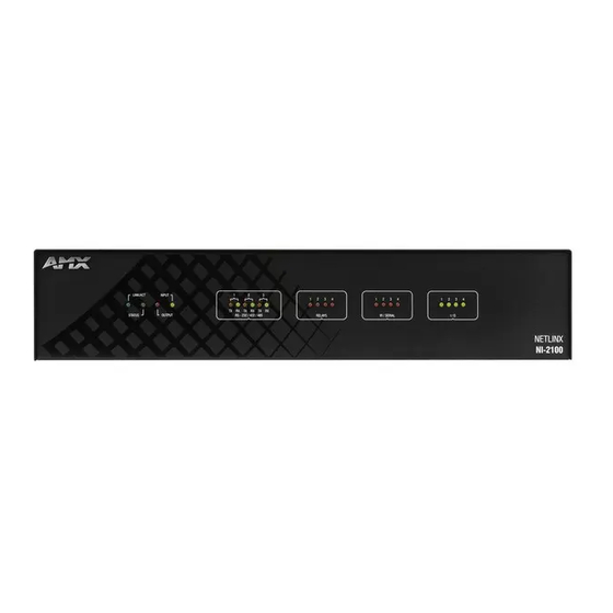
OUTPUT LED
INPUT LED
STATUS LED
LINK/ACT LED
front
RS-232/422/485 (Ports 1-3)
rear
Relays (Port 4)
I/O (Port 9)
IR/Serial (Ports 5-8)
PROGRAM Port
CONFIGURATION DIP Switch
FIG. 1
NI-2100
ATTENTION!
Verify you are using the latest NI firmware for the on-board Master. Verify you are using the
latest version of NetLinx Studio (available for download from www.amx.com).
Specifications
NI-2100 Specifications
Models Available:
• NI-2100 Controller (FG2105-04)
The NI-2100 can be upgraded to provide one ICSHub and two
ICSNet ports by installing the optional ICSNet daughter card
(FG2105-10 - see Other AMX Equipment)
• NI-2100/ICS Controller with ICSNet (FG2105-14)
Dimensions
• 3 1/2" x 17" x 3 1/2" (8.8 cm x 43.2 cm x 8.8 cm)
(HWD):
• RU: 2
Power
700 mA @ 12 VDC
Requirement:
Memory:
• 64 MB SDRAM
• 1 MB Non-volatile (NV) SRAM
Compact Flash:
2GB or greater (upgradeable to 4GB - see Other AMX Equipment).
Note: AMX may increase Flash size at any time in response to
market availability.
Weight:
4.50 lbs (2.04 kg)
Enclosure:
Metal with black matte finish
Certifications:
FCC Part 15 Class B, CE, and IEC 60950
Front Panel LEDs:
LINK/ACT
Blinks when the Ethernet cables are connected and terminated
(green):
correctly. Also blinks when receiving Ethernet data packets.
Status (green):
Blinks to indicate that the system is programmed and
communicating properly.
Output (red):
Blinks when the Controller transmits data, sets channels On and
Off, sends data strings, etc.
Input (yellow):
Blinks when the Controller receives data from button pushes,
strings, commands, channel levels, etc.
RS-232/422/485
3 sets of LEDs light to indicate that DB9 Ports 1 - 3 are transmitting
(red / yellow):
or receiving RS-232, 422, or 485 data (red = TX, yellow = RX).
Relay (red):
4 LEDs light to indicate the relay channels 1 - 4 are active (closed).
These LEDs reflect the state of the relay on Port 4.
IR/Serial (red):
4 LEDs light to indicate the IR/Serial channels 1 - 4 are transmitting
control data on Ports 5 - 8. LED indicator for each IR port remains lit
for the length of time that IR/Serial data is being generated.
I/O (yellow):
Lights when the I/O channels 1 - 4 are active. The LED for each I/O
port reflects the state of that particular port.
RS-232/422/485 Status LEDs
RELAY Status LEDs
IR/SERIAL Status LEDs
I/O Status LEDs
ICSNet/ICSHub Ports
(provided by optional
ICSNet daughter card)
ID Pushbutton
ETHERNET
10/100 Port
AxLink Port
12 VDC PWR Connector
NI-2100
NetLinx Integrated Controller
NI-2100 Specifications (Cont.)
Rear Panel Components:
RS-232/422/485
3 RS-232/422/485 control ports using DB9 (male) connectors with
(Ports 1 - 3):
XON/XOFF (transmit on/transmit off), CTS/RTS (clear to send/
ready to send), and 300-115,200 baud.
ICSNet:
2 RJ-45 connectors for ICSNet interface (provided by optional
ICSNet daughter card).
ICSHub Out:
RJ-45 connector provides data to a Hub connected to the Controller
(provided by optional ICSNet daughter card).
Relay (Port 4):
• 4-channel single-pole single-throw relay ports
• Each relay is independently controlled.
• Supports up to 4 independent external relay devices
• Channel range = 1-4
• Each relay can switch up to 24 VDC or 28 VAC @ 1 A
• 8-pin 3.5 mm mini-Phoenix (female) connector provides relay
termination
Digital I/O
4-channel binary I/O port for contact closure with each input being
(Port 9):
capable of voltage sensing. Input format is software selectable with
interactive power sensing for IR ports.
Note: The I/Os on this card are not dry closure; they are electronic
switches that float at 5V when Off. Therefore, they should not be
expected to work in situations that require true dry contact (or dry
closure). The I/Os do work with AMX PC1, PC2, UPC20 and
UPC20+.
IR/Serial
4 IR/Serial control ports support high-frequency carriers of up to
(Ports 5 - 8):
1.142 MHz with each output being capable of two electrical formats:
IR or Serial.
• 4 IR/Serial data signals can be generated simultaneously.
• IR ports support data mode (at limited baud rates and wiring
distances).
Program Port:
RS-232 DB9 connector (male) can be connected to a DB9 port on a
PC. This connector can be used with serial and NetLinx program-
ming commands, as well as other DB9 capable devices, to both
upload/download information from the NetLinx Studio program.
Configuration DIP
Sets the communication parameters for the Program port (see Baud
Switch:
Rate Settings).
ID Pushbutton:
Sets the NetLinx ID (Device only) assignment for the device.
Ethernet Port:
RJ-45 connector provides TCP/IP communication. This is an Auto
MDI/MDI-X enabled port, which allows you to use either straight-
through or crossover Ethernet cables.
The Ethernet Port LEDs show communication activity, connection
status, speeds, and mode information:
• SPD (speed) - Yellow LED lights On when the connection speed
is 100 Mbps and turns Off when the speed is 10 Mbps.
• L/A (link/activity) - Green LED lights On when the Ethernet cables
are connected and terminated correctly, and blinks when
receiving Ethernet data packets.
AxLink Port:
4-pin 3.5 mm mini-Phoenix (male) connector that provides data and
power to external control devices. Green AXlink LED indicates the
state of the AXlink port.
Power Port:
2-pin 3.5 mm mini-Phoenix (male) connector.
Operating
• Operating Temperature: 0° C (32° F) to 50° C (122° F)
Environment:
• Operating Humidity: 20% to 85% RH
• Heat Dissipation (Typical): 28.7 BTU/hr
Included
• 2-pin 3.5 mm mini-Phoenix (female) PWR connector (41-5025)
Accessories:
• 4-pin 3.5 mm mini-Phoenix (female) AXlink connector (41-5047)
• 6-pin 3.5 mm mini-Phoenix female I/O connector (41-5063)
• 8-pin 3.5 mm mini-Phoenix female Relay connector (41-5083)
• Installation Kit (KA2105-01):
8-pin Relay Common Strip
4 rack mount screws
4 washers
• 2 CC-NIRC NetLinx IR Emitter Cables (FG10-000-11)
• 2 removable rack ears (62-2105-07)
Other AMX
• 2-pin 3.5 mm mini-Phoenix male connector (41-5026)
Equipment:
• CC-COM Programming Port Cable (FG10-727)
• CC-NSER IR/Serial cable (FG10-007-10)
• ICSNet daughter card (FG2105-10)
• NCK, NetLinx Connector Kit (FG2902)
• STS, Serial To Screw Terminal (FG959)
• Upgrade Compact Flash (factory programmed with firmware):
NXA-CF2NI4G, 4 GB Flash Upgrade (FG2116-07)
Installation Guide
Advertisement

Related Manuals for AMX NI-2100


Summary of Contents for AMX NI-2100
- Page 1 The NI-2100/ICS is ideal for control and automation of medium-sized rooms and multi-room NI-2100 Specifications (Cont.) applications. The NI-2100 has 64MB of onboard RAM and is Device Discovery enabled to simplify programming by standardizing device and function definitions, default touch panel Rear Panel Components: button assignments, and control and feedback methods.
- Page 2 ©2010 AMX. All rights reserved. AMX and the AMX logo are registered trademarks of AMX. AMX reserves the right to alter specifications without notice at any time. 3000 RESEARCH DRIVE, RICHARDSON, TX 75082 • 800.222.0193 • fax 469.624.7153 • technical support 800.932.6993 • www.amx.com...