
Related Manuals for Quectel Smart EVB G5


Summary of Contents for Quectel Smart EVB G5
- Page 1 Smart EVB G5 User Guide Smart Module Series Version: 1.0 Date: 2022-01-18 Status: Released...
- Page 2 Smart Module Series At Quectel, our aim is to provide timely and comprehensive services to our customers. If you require any assistance, please contact our headquarters: Quectel Wireless Solutions Co., Ltd. Building 5, Shanghai Business Park Phase III (Area B), No.1016 Tianlin Road, Minhang District, Shanghai...
- Page 3 Except as otherwise set forth herein, nothing in this document shall be construed as conferring any rights to use any trademark, trade name or name, abbreviation, or counterfeit product thereof owned by Quectel or any third party in advertising, publicity, or other aspects.
-
Page 4: Safety Information
Manufacturers of the cellular terminal shall notify users and operating personnel of the following safety information by incorporating these guidelines into all manuals of the product. Otherwise, Quectel assumes no liability for customers’ failure to comply with these precautions. -
Page 5: About The Document
Smart Module Series About the Document Revision History Version Date Author Description 2022-01-14 Mary SHEN Creation of the document 2022-01-18 Mary SHEN First official release Smart_EVB_G5_User_Guide 4 / 66... -
Page 6: Table Of Contents
Special Mark ..........................10 Product Overview ..........................11 Key Features ..........................11 Top and Bottom Views ......................13 Component Placement of Smart EVB G5 ................15 Smart EVB G5 Kit Accessories ....................... 19 Accessories Assembly ......................19 List of Accessories ........................20 Interface Application ........................ - Page 7 Smart Module Series Switches and Buttons ......................56 Status Indicators ........................57 Operation Procedures ........................59 Turn On the Module ......................... 59 Turn Off the Module ......................... 60 Communication via USB ......................61 Communication via UART Interface..................62 Firmware Upgrade ........................63 Appendix References ........................
- Page 8 Table 1: Applicable Modules ..........................10 Table 2: Special Mark ............................10 Table 3: Key Features ............................11 Table 3: Components & Functions of Smart EVB G5 ..................16 Table 5: Accessories List ........................... 20 Table 6: Description of Power Supply ........................ 22 Table 7: Pin Definition of Battery Interface ......................
- Page 9 Figure 1: Smart EVB G5 Top View ........................13 Figure 2: Smart EVB G5 Bottom View ....................... 14 Figure 3: Top View for Component Placement of Smart EVB G5 ..............15 Figure 4: Bottom View for Component Placement of Smart EVB G5 ............... 16 Figure 5: Smart EVB G5 and Accessories......................
- Page 10 Smart Module Series Figure 42: ERM-Type Vibrator ........................... 56 Figure 43: Switches ............................57 Figure 44: Buttons ............................. 57 Figure 45: Status Indicators ..........................58 Figure 46: LCD Display Indicating Module’s Turn-on ..................59 Figure 47: LCD Menu Display for Turning Off Module ..................60 Figure 48: USB Ports ............................
-
Page 11: Introduction
Smart Module Series Introduction This user guide describes the application details of the Smart EVB G5 (evaluation board), which is an assistant tool for engineers to develop applications and test basic functions of applicable modules below. Applicable Modules Table 1: Applicable Modules... -
Page 12: Product Overview
Smart Module Series Product Overview Key Features Table 3: Key Features Features Implementation ⚫ DC power supply: 5–36 V (typical: 5 V) Power supply ⚫ VBAT: 3.55–4.4 V (typical: 3.8 V) ⚫ Two 5-inch 1280 × 720 HD resolution LCDs LCM interfaces ⚫... - Page 13 Smart Module Series Support two UART interfaces: Main UART for data transmission and AT command communication ⚫ UART interfaces ⚫ Debug UART for debugging SD card interface Support 4-bit SD card with hot-plug detection MIPI + SPI/I2S interface* A group of 4-lane MIPI_DSI interface and SPI/I2S interface Support 2 flashlight LEDs for testing the module’s flashlight function Flashlights Support three sensors including ALS/PS, accelerometer/gyroscope and...
-
Page 14: Top And Bottom Views
Smart Module Series Top and Bottom Views Figure 1: Smart EVB G5 Top View Smart_EVB_G5_User_Guide 13 / 66... - Page 15 Smart Module Series Figure 2: Smart EVB G5 Bottom View Smart_EVB_G5_User_Guide 14 / 66...
-
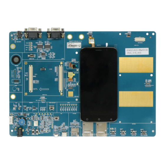
Page 16: Component Placement Of Smart Evb G5
J1201 J0403 J0402 J0803 J0801 BAT0201 J0401 U0301 S0501 U0304 U1201 U0302 J0202 S0601 U0202 J0201 J0601 J0602 J1101 J1001 J1002 S0502 S0503 S0505 S0504 Figure 3: Top View for Component Placement of Smart EVB G5 Smart_EVB_G5_User_Guide 15 / 66... - Page 17 Smart Module Series J1203 J1204 Figure 4: Bottom View for Component Placement of Smart EVB G5 Table 4: Components & Functions of Smart EVB G5 Components RefDes. Description ⚫ Power jack on the EVB J0201 ⚫ Typical power supply: +5 V Power supply ⚫...
- Page 18 Charging status indicator D0503 Module turn-on/turn-off indicator Smart TE-A interface J0101, J0102 Connectors for connecting Smart TE-A with Smart EVB G5 Rear camera connector, support 16M CMOS sensor with J0401 auto-focusing function Front camera connector, support 8M CMOS sensor with...
- Page 19 Smart Module Series J0803 Connector for main LCM J0804 ZIF connector for main touch panel LCM and TP interfaces J0801 Connector for secondary LCM J0802 ZIF connector for secondary touch panel U0301 Accelerometer and gyroscope sensor Sensors U0302 Geomagnetic sensor U0304 Ambient light sensor (ALS) and proximity sensor (PS) Test module’s motor driver interface...
-
Page 20: Smart Evb G5 Kit Accessories
Smart Module Series Smart EVB G5 Kit Accessories Accessories Assembly Figure 5: Smart EVB G5 and Accessories NOTE The assembly method shown in the figure above is for reference only. Smart_EVB_G5_User_Guide 19 / 66... -
Page 21: List Of Accessories
Smart Module Series List of Accessories All accessories of Smart EVB G5 kit are listed as below. Please contact the supplier if there is something missing. USB to RS232 USB Type-C cable 5V DC adapter converter cable GNSS antenna Headset USB flash disk Bolts&... - Page 22 USB flash disk USB driver Related tools for modules Bolts and Nuts Bolts and coupling nuts for fixing Smart EVB G5 4 for each A sheet of paper giving instructions for EVB connection, Instruction Sheet details of EVB accessories, etc.
-
Page 23: Interface Application
Smart EVB G5. Power Supply The Smart EVB G5 can be powered by an external 5 V DC power adapter through the power jack J0201 and the step-down converter (DC-DC converter), which is used to convert 5 V DC power supply voltage to 4.0 V for powering up the module. -
Page 24: Adapter Interface
Figure 7: Simplified Power Supply Block Diagram of Smart EVB G5 4.1.1. Adapter Interface The following figure shows the DC power jack of the Smart EVB G5. Figure 8: 5 V DC Power Jack When the power jack is used for power supply, the power plug design of the adapter is shown as below. -
Page 25: Battery Interface
Smart Module Series 4.1.2. Battery Interface The following figure shows a reference circuit design for battery interface. J0202 VBAT VBAT VBAT BAT_THERM TEMP 47 K 100 uF 1 nF 100 pF Battery Figure 10: Reference Design for Battery Interface The following figure shows the pin assignment of battery interface. The following table shows the pin definition of the battery connector. -
Page 26: Smart Te-A Interface
The Smart TE-A interface includes two B2B connectors J0101 and J0102. Smart TE-A is connected to the EVB via the two connectors. Table 8: Description of Smart TE-A Interface RefDes. Description J0101 Connectors for connecting Smart TE-A with Smart EVB G5 J0102 Smart_EVB_G5_User_Guide 25 / 66... - Page 27 Smart Module Series The following two figures show the two B2B connectors and the sketch map of the Smart TE-A. J0101 J0102 Figure 12: B2B Connectors Figure 13: Sketch Map of Smart TE-A (Top View) Smart_EVB_G5_User_Guide 26 / 66...
- Page 28 Smart Module Series The following table describes the pin definition of the two B2B connectors J0101 and J0102. Table 9: Pin Definition of B2B Connector J0101 Pin No. Pin Name 1, 11, 37, 71, 83, 90, 94, 101, 103, 104, 109–111, 116, 122, 127–129, 134, 139, 140 LCD_RST1 UART1_CTS...
- Page 29 Smart Module Series 38, 105, 107 USB_VBUS 40, 56 SEL_SW SD_LDO12 LDO2_1V1 I2S_MCLK/LCD_TE1 TP2_CC_HDMI_I2C_SDA CS_PLUS TP2_CC_HDMI_I2C_SCL CS_MINUS CHG_LED PMU_MPP2 GRENN_LED DSI_PWM CS_N MAG_INT CS_P TP2_HDMI_INT FORCE_USB_BOOT GPIO_8 CAM_1V2_EN HAP_P SENSOR_I2C_SCL HAP_N Smart_EVB_G5_User_Guide 28 / 66...
- Page 30 Smart Module Series SENSOR_I2C_SDA LCD_BL_A GYROSCOPIC_INT LCD_BL_K1 FSYNC/INT2 LCD_BL_K2 ALPS_INT GPIO_7 LDO23_1V2 LCD_BL_K3 LDO5_1V8 LCD_BL_K4 LDO6_1V8 LDO10_2V8 FM_ANT LDO22_2V8 LDO17_2V85 HPH_R HPH_REF VRTC HPH_L HS_DET SPK_P SPK_N EAR_P Smart_EVB_G5_User_Guide 29 / 66...
- Page 31 Smart Module Series 113, 115, 117, 119, 121, 123, 125 VBAT EAR_N MIC_BIAS1 MIC_GND MIC3_P BATT_MINUS MIC2_P BATT_PLUS VBAT_SNS MIC1_N BAT_THERM MIC1_P Table 10: Pin Definition of B2B Connector J0102 Pin No. Pin Name USIM1_VDD 2, 8, 14, 20, 21, 23, 26, 29, 32, 35, 41, 47, 53, 59, 65, 73, 79, 85, 90, 91, 94, 97, 98, 102, 103, 109, 114, 115, 120, 121, 126, 132, 139 USIM1_DET...
- Page 32 Smart Module Series DSI1_LN2_P USIM2_DET USIM2_RST DSI1_LN1_N USIM2_CLK DSI1_LN1_P USIM2_DATA DSI1_LN0_N DSI1_LN0_P DSI1_CLK_N DSI1_CLK_P TP_RST TP_INT DSI0_LN3_P TP_I2C_SCL(TP2_CC_HDMI_I2C_SCL) DSI0_LN3_N TP_I2C_SDA(TP2_CC_HDMI_I2C_SDA) LCD_TE DSI0_LN2_P LCD_RST DSI0_LN2_N GPIO_16 I2S_MCLK DSI0_LN1_P CTP_EN DSI0_LN1_N Smart_EVB_G5_User_Guide 31 / 66...
- Page 33 Smart Module Series SPI_CLK_I2S_CLK SPI_MISO_I2S_D1 DSI0_LN0_P SPI_MOSI_I2S_D0 DSI0_LN0_N SPI_CS_I2S_WS GPIO1_EXT DSI0_CLK_P GPIO2_EXT DSI0_CLK_N PWRKEY EN_AVDD_CAM RESET_N PMI_MPP1 CSI1_LN1_P CSI1_LN1_N SCAM_PWDN SCAM_RST CSI1_LN0_P CAM_I2C_SDA CSI1_LN0_N CAM_I2C_SCL MCAM_PWDN CSI1_CLK_P MCAM_RST CSI1_CLK_N Smart_EVB_G5_User_Guide 32 / 66...
- Page 34 Smart Module Series CSI0_LN3_P CSI0_LN3_N SCAM_MCLK CSI0_LN2_P MCAM_MCLK CSI0_LN2_N FLASH_LED1 CSI0_LN1_P FLASH_LED2 CSI0_LN1_N USB_ID GPIO_6 CSI0_LN0_P USB_OTG_PWR_EN CSI0_LN0_N CSI0_CLK_P CSI0_CLK_N TX_M SD_LDO11 TX_P TX_M SD_LDO11 TX_P SD_CMD Smart_EVB_G5_User_Guide 33 / 66...
-
Page 35: Lcm Interfaces
25, 27, 31, 33, 64, 66, 70, 72, 74, 76, 92, 134, 140 LCM Interfaces The Smart EVB G5 provides two LCM interfaces and can be equipped with two LCD modules for dual display function. Currently, the Smart EVB G5 provides two 5-inch 1280 × 720 HD resolution liquid crystal displays for customers to test. -
Page 36: Main Lcm Interface
Smart Module Series 4.3.1. Main LCM Interface The following figure shows a reference circuit design for main LCM interface of the Smart EVB G5. VDD_2V8 LCM_IO J0803 LCD_BL_A LEDA LCD_BL_K1 LEDK LCD_BL_K2 LPTE LCD0_TE RESET LCD0_RST LCD_ID PMI_ MPP1 NC (SDA-TP) -
Page 37: Secondary Lcm Interface
Smart Module Series 4.3.2. Secondary LCM Interface The following figure shows a reference circuit design for secondary LCM interface of the Smart EVB G5. VDD_2V8 LCM_IO J0801 LCM1_LED+ LEDA LCM1_LED- LEDK LPTE LCD1_TE RESET LCD1_RST LCD_ID PMU_MPP2 NC (SDA-TP) NC (SCL-TP) -
Page 38: Backlight Driver For Secondary Lcm Interface
Figure 16: Pin Assignments of LCM Interfaces 4.3.3. Backlight Driver for Secondary LCM Interface The Smart EVB G5 uses a PWM dimming step-up LED driver for the WLED backlighting of secondary LCM interface. The following figure shows a reference circuit design for the backlight driver. -
Page 39: Touch Panel Interfaces
Smart Module Series Touch Panel Interfaces The Smart EVB G5 provides two touch panel interfaces: Table 12: Description of Touch Panel Interfaces RefDes. Description J0804 ZIF connector for main touch panel J0802 ZIF connector for secondary touch panel The following figure shows a reference design for touch panel interfaces. -
Page 40: Camera Interfaces
TP_INT Ground 2.8V power supply for touch panel VDD power Camera Interfaces Smart EVB G5 provides three camera interfaces (4-lane + 2-lane + 1-lane) with rear camera, front camera and depth camera assembled. Table 14: Description of Camera Interfaces RefDes. - Page 41 Smart Module Series The following figure shows a reference design for camera interfaces. AF_VDD AFVDD_2V8 AVDD AVDD_2V95 DVDD DVDD_1V1 DOVDD DOVDD_1V8 MCAM_RST MCAM_PWDN 2.2K 2.2K MCAM_MCLK CAM_I2C_ SDA CAM_I2C_ SCL CSI0_LN3_P CSI0_LN3_N CSI0_LN2_P CSI0_LN2_N CSI0_LN1_P CSI0_LN1_N CSI0_LN0_P CSI0_LN0_N AVDD 4.7uF CSI0_ CLK_P CSI0_ CLK_N DOVDD...
-
Page 42: Usb Interfaces
The following figure shows the camera interfaces with cameras assembled. Figure 21: Camera Interfaces with Cameras Assembled USB Interfaces The Smart EVB G5 provides two USB interfaces: a micro-USB interface and a type-C interface. Table 15: Description of USB Interfaces RefDes. -
Page 43: Audio Interfaces
Smart EVB G5 provides three groups of analog audio outputs: one mono loudspeaker, one mono earphone, and one stereo headset. The Smart EVB G5 further provides three groups of analog audio inputs: two single-ended microphone inputs and one differential microphone input. One single-ended microphone input is used for headset interface. -
Page 44: Loudspeaker Interface
Audio jack for headset 4.7.1. Loudspeaker Interface Smart EVB G5 provides one loudspeaker interface and the loudspeaker is soldered onto the Smart EVB G5 via test point J1203. The following figure shows a reference circuit design for loudspeaker interface. 1.0nF... -
Page 45: Headset Interface
Smart Module Series 4.7.2. Headset Interface The following figure shows a reference circuit design for headset interface. J1202 MIC2_P 33 R HPH_R 100 pF 33 R HPH_L HPH_REF HS_DET 10 K 10 K D1 D2 D3 D4 D5 Module 33pF 33pF 33pF Figure 25: Reference Design for Headset Interface The following figure shows the pin assignment of headset interface. -
Page 46: Earphone Interface
Figure 27: Sketch of Audio Plug 4.7.3. Earphone Interface Smart EVB G5 provides one earphone interface and the earphone is soldered onto the Smart EVB G5 via test point J1204. The following figure shows a reference circuit design for earphone interface. -
Page 47: Microphone Interfaces
Figure 28: Reference Design for Earphone Interface 4.7.4. Microphone Interfaces Smart EVB G5 provides one single-ended microphone input and one differential microphone input for microphone interfaces. The single-ended microphone input is for MEMS-type microphone and the differential microphone input is for ECM-type microphone. The following figures show a reference circuit design for microphone interfaces. -
Page 48: (U)Sim Card Interfaces
ECM-Type MEMS-Type Figure 30: MEMS-Type and ECM-Type Microphones (U)SIM Card Interfaces The Smart EVB G5 provides two 6-pin push-push type (U)SIM card (1.8/2.95 V) connectors which support 1.8/2.95 V (U)SIM card. Table 18: Description of (U)SIM Card Interfaces RefDes. Description... - Page 49 Smart Module Series The following figure shows the simplified interface schematic for J1001. USIM_VDD LDO_1V8 10 K J1001 NM-100 K USIM_ VDD GND1 22 R USIM_ RST GND2 22 R USIM_ CLK 22 R USIM_ DATA DATA USIM_ DET Module 100 nF 22 pF 22 pF...
-
Page 50: Uart Interfaces
The reference circuit and pin assignment of J1002 are the same as J1001’s. UART Interfaces Smart EVB G5 provides two UART interfaces: main UART and debug UART. The main UART interface can be used for data transmission and AT command communication. The debug UART interface is used for debugging. - Page 51 Smart Module Series 1.8V 3.3V VCCA VCCB UART_TXD TXD _3.3V TXD_1.8V DIN 1 DOUT1 UART_RTS RTS_1.8V RTS_3.3V DIN 2 DOUT2 DIN 3 DOUT3 DIN 4 DOUT4 DIN 5 DOUT5 R1OUTB UART_RXD RXD _1.8V RXD _3.3V ROUT 1 RIN1 ROUT 2 RIN2 CTS _1.8V CTS _3.3V...
-
Page 52: Sd Card Interface
The level match circuit and pin assignment of J1302 are the same as those of J1301. SD Card Interface Smart EVB G5 provides an SD card interface for customers to test the module’s SD card interface. Table 22: Description of SD Card Interface RefDes. - Page 53 Smart Module Series Figure 36: Pin Assignment of SD Card Interface Table 23: Pin Definition of SD Card Connector Pin No. Pin Name Description SD_DATA2 SDIO data bit 2 SD_DATA3 SDIO data bit 3 SD_CMD SD card command SD card power supply SD_CLK SD card clock power ground (GND)
-
Page 54: Flashlights
RefDes. Description D0301 Flashlight LED1 for testing module’s flashlight interface D0302 Flashlight LED2 for testing module’s flashlight interface The following figures show a reference circuit design for flashlights and their locations on Smart EVB G5. D0301 FLASH_LED1 D0302 FLASH_LED2 Module... -
Page 55: Sensors
Smart Module Series Sensors Smart EVB G5 provides three sensors for testing purpose, as shown in the table and figure below. Table 25: Description of Sensors RefDes. Description U0301 Accelerometer and gyroscope sensor U0302 Geomagnetic sensor U0304 Ambient light sensor (ALS) and proximity sensor (PS) -
Page 56: Vibrator
The following figures show a reference circuit design for the emergency download interface. LDO5_1V8 USB_BOOT Module Figure 40: Reference Design for USB_BOOT Vibrator Smart EVB G5 provides an ERM-type vibrator for customers to test the motor driver interface of Smart modules. Table 26: Description of Vibrator RefDes. Description U0305 Test module’s motor driver interface. -
Page 57: Switches And Buttons
Smart Module Series Figure 42: ERM-Type Vibrator Switches and Buttons Smart EVB G5 includes four switches and four buttons, which are illustrated in the following tables and figures. Table 27: Description of Switches RefDes. Description S0201 Used to select DC power supply or battery power supply... -
Page 58: Status Indicators
The switches are shown in following figures. S0501 S0201 S0202 S0601 Figure 43: Switches Smart EVB G5 provides four buttons S0502, S0503, S0504 and S0505, which are PWRKEY, RESET, VOL DOWN and VOL UP respectively. The buttons are shown in the following figure. S0502 S0503 S0505... - Page 59 Smart Module Series ⚫ Extinct: module stops being charged D0503 Indicates whether the module is turned on Figure 45: Status Indicators Smart_EVB_G5_User_Guide 58 / 66...
-
Page 60: Operation Procedures
Smart Module Series Operation Procedures This chapter introduces how to use the Smart EVB G5 for testing and evaluation of applicable modules. Before the procedures below, please ensure modules and the EVB are correctly assembled. Turn On the Module Step 1: Connect the module TE-A to the Smart EVB G5 through connectors J0101 and J0102. -
Page 61: Turn Off The Module
Smart Module Series NOTE After power supply is provided (i.e., Step 3 mentioned above), inserting a USB cable into USB interface of EVB can also turn on the module. Turn Off the Module There are two methods to turn off the module. The steps for the first method are as follows: Step 1: Press D0501 (PWRKEY) for at least 1s under the turn-on state of the module, and then the LCD will display a menu for selection as shown in the following figure:... -
Page 62: Communication Via Usb
Step 1: Turn on the module according to the procedures in Chapter 5.1. Step 2: Connect Smart EVB G5 with PC using USB cable through USB interface and then run the USB flash disk on PC to install the USB driver and ADB driver. The USB port numbers can be viewed in Device Manager of the PC when the USB driver is installed, as shown below. -
Page 63: Communication Via Uart Interface
Figure 50: USB Serial Port for UART Step 3: Install and then use the QCOM tool provided by Quectel to realize the communication between the smart module and the PC. The following figure shows the QCOM configuration: select correct “COM port”... -
Page 64: Firmware Upgrade
Smart Module Series Figure 51: QCOM Configuration When Connecting USB Serial Port Firmware Upgrade Firmware of the module is upgraded via USB port by default. Please refer to the following procedures to upgrade firmware through the EVB. Step 1: Install and open the firmware upgrade tool QFIL on PC and then turn on the smart module according to the procedures mentioned in Chapter 5.1. - Page 65 Smart Module Series Figure 52: Firmware Upgrade Steps Smart_EVB_G5_User_Guide 64 / 66...
-
Page 66: Appendix References
Smart Module Series Appendix References Table 30: Related Documents Document name [1] Quectel_SC200L_Series_Hardware_Design [2] Quectel_SC200E_Series_Reference_Design [3] Quectel_QCOM_User_Guide Table 31: Terms and Abbreviations Abbreviation Description Ambient Light Sensor CMOS Complementary Metal Oxide Semiconductor Electret Condenser Microphone Evaluation Board LCD Module Light Emitting Diode MEMS Micro-Electro-Mechanical System MIPI... - Page 67 Smart Module Series Universal Serial Bus (Universal) Subscriber Identity Module (U)SIM White LED WLED Zero Insert Force Smart_EVB_G5_User_Guide 66 / 66...