Table of Contents
Advertisement
Quick Links
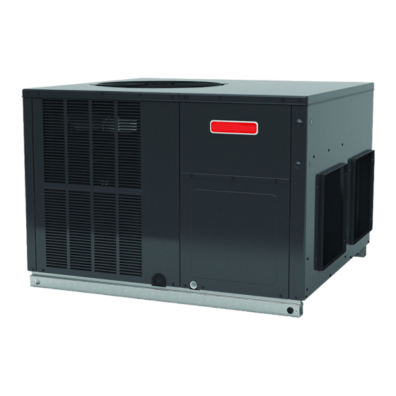
Installation Instructions for Self-Contained Package
Heat Pump Units GPHM5 15.2 SEER2 "M" SERIES (2-4 Ton)
Affix this manual and Users Information Manual
adjacent to the unit.
Do not bypass safety devices.
Our continuing commitment to quality products may mean a change in specifications without notice.
IOG-3030A
10/2022
WARNING
Daikin Comfort Technologies Manufacturing, L.P.
19001 Kermier Rd. Waller, TX 77484
© 2022 Daikin Comfort Technologies Manufacturing, L.P.
ONLY PERSONNEL THAT HAVE BEEN TRAINED TO
INSTALL, ADJUST, SERVICE, MAINTENANCE OR REPAIR
(HEREINAFTER, "SERVICE") THE EQUIPMENT SPECIFIED
IN THIS MANUAL SHOULD SERVICE THE EQUIPMENT. THE
MANUFACTURER WILL NOT BE RESPONSIBLE FOR ANY
INJURY OR PROPERTY DAMAGE ARISING FROM IMPROPER
SERVICE OR SERVICE PROCEDURES. IF YOU SERVICE THIS
UNIT, YOU ASSUME RESPONSIBILITY FOR ANY INJURY OR
PROPERTY DAMAGE WHICH MAY RESULT. IN ADDITION, IN
JURISDICTIONS THAT REQUIRE ONE OR MORE LICENSES
TO SERVICE THE EQUIPMENT SPECIFIED IN THIS MANUAL,
ONLY LICENSED PERSONNEL SHOULD SERVICE THE
EQUIPMENT. IMPROPER INSTALLATION, ADJUSTMENT,
SERVICING, MAINTENANCE OR REPAIR OF THE EQUIPMENT
SPECIFIED IN THIS MANUAL, OR ATTEMPTING TO INSTALL,
ADJUST, SERVICE OR REPAIR THE EQUIPMENT SPECIFIED
IN THIS MANUAL WITHOUT PROPER TRAINING MAY RESULT
IN PRODUCT DAMAGE, PROPERTY DAMAGE, PERSONAL
INJURY OR DEATH.
ATTENTION INSTALLING PERSONNEL:
Prior to installation, thoroughly familiarize yourself with this
Installation Manual. Observe all safety warnings. During
installation or repair, caution is to be observed.
It is your responsibility to install the product safely and to
educate the customer on its safe use.
These installation instructions cover the outdoor
installation of self contained package air conditioners and
heating units. See the Specification Sheets applicable to
your model for information regarding accessories.
*NOTE: Please contact your distributor or our website
for the applicable Specification Sheets referred to in this
manual.
www.goodmanmfg.com
WARNING
RECOGNIZE THIS SYMBOL
AS A SAFETY PRECAUTION.
Advertisement
Table of Contents
Troubleshooting

Related Manuals for Daikin GPHM5 SEER2 M Series


Summary of Contents for Daikin GPHM5 SEER2 M Series
- Page 1 Specification Sheets referred to in this manual. Our continuing commitment to quality products may mean a change in specifications without notice. Daikin Comfort Technologies Manufacturing, L.P. IOG-3030A 19001 Kermier Rd. Waller, TX 77484 www.goodmanmfg.com 10/2022 © 2022 Daikin Comfort Technologies Manufacturing, L.P.
-
Page 2: Table Of Contents
TABLE OF CONTENTS AIRFLOW MEASUREMENT AND ADJUSTMENT ..12 Total External Static Pressure ......13 ADJUSTING SPEED TAP FOR ID BLOWER MOTOR ...13 TO THE INSTALLER ............2 ECM Motor Speed Adjustment .......13 SHIPPING INSPECTION ...........3 GPHM5 Dip Switch Functions ........13 Checking Products Received ........3 GPHM5 CFM Delivery and Adjustments ....13 Message to the Homeowners ........3 GPHM5 Thermostat “Fan Only”... -
Page 3: Shipping Inspection
This type of use may result in premature failure of the unit HOMEOWNER SUPPORT due to extremely low return air temperatures and exposure to corrosive or very dirty atmospheres. DAIKIN COMFORT TECHNOLOGIES MANUFACTURING, L.P. 19001 KERMIER ROAD WALLER, TX 77484 885-770-5678... -
Page 4: Epa Regulations
Specification sheets can be found at www.goodmanmfg. Clearances and Accessibility com for Goodman® brand products. Within the website, The unit is designed to be located outside the building with please select the residential or commercial products menu unobstructed condenser air inlet and discharge. Additionally, and then select the submenu for the type of product to be the unit must be situated to permit access for service and installed, such as air conditioners or heat pumps, to access... -
Page 5: Roof Top Installation Details
Heat pumps require special location consideration in areas Curbing must be installed in compliance with the National of heavy snow accumulation and/or areas with prolonged Roofing Contractors Association Manual. Construct duct continuous subfreezing temperatures. Heat pump unit work using current industry guidelines. The duct work must bases have holes under the outdoor coil to permit drainage be placed into the roof curb before mounting the package of defrost water accumulation. -
Page 6: Circulating Air And Filters
Horizontal Air Flow CAUTION Single phase models are shipped without horizontal duct covers. If needed, these kits may be ordered through Daikin’s Service Parts department. To avoid possible personal injury, a safe, flat surface for service personnel should be provided. WARNING To prevent possible equipment damage, property damage, personal injury or death. -
Page 7: Manufactured Home Mod Kit
as indicated. Ducts should run as directly as possible It is strongly encouraged to use appropriately sized ducts to supply and return outlets. Use of non-flammable based upon the CFM for your application (unit’s CFM). If weatherproof flexible connectors on both supply and return duct sizing through industry manuals or air duct calculators connections at the unit to reduce noise transmission is requires larger ducts than converter openings, run larger... -
Page 8: Electrical Wiring
ELECTRICAL WIRING DO NOT EXCEED THE MAXIMUM OVERCURRENT DEVICE SIZE SHOWN ON UNIT DATA PLATE. CAUTION Fuses or HACR type circuit breakers may be used where codes permit. To avoid property damage or personal injury due to fire, use only copper conductors. IMPORTANT NOTE: Units may be equipped with a single-pole contactor. -
Page 9: Internal Wiring
4. Turn the fan switch to the “ON” position. The blower DP5HM[24-48] should begin ramping up immediately. Terminal Thermostat 5. Turn the fan switch to “AUTO” position. The blower R (24V) should begin ramping down after an approximate 60-second delay. Green G (Fan) 6. -
Page 10: Final System Checks
NOTE: If outdoor thermostats are installed, the 2. Crankcase Heater - This item is “ON” whenever outdoor ambient must be below the setpoint of these power is supplied to the unit and the crankcase thermostats for the heaters to operate. It may be heater thermostat is closed. -
Page 11: Indoor Blower Motor
10. Indoor Blower Motor - Units with ECM Motors. TYPICAL HEAT PUMP SYSTEM IN HEATING The ECM model indoor blower motor is activated by the room thermostat by cooling/heating or fan “ON” position. ECM motors are constant torque motors with the very low power consumption. -
Page 12: Suggested Field Testing/ Troubleshooting
thermostat calls for heat. At the end of the timing period, the unit’s defrost cycle will be initiated provided the sensor remains closed. When the sensor opens (approximately 60 ± 5°F), the defrost cycle is terminated and the timing period is reset. -
Page 13: Total External Static Pressure
NOTE: Never run CFM below 300 CFM per ton, HEATING COOLING evaporator freezing or poor unit performance is Speed Lead Speed Lead possible. Definition Definition Color Color Low Speed Total External Static Pressure White Purple Speed Heat Cool 1. Using a digital manometer measure the static High High Speed pressure of the return duct at the inlet of the unit... -
Page 14: Units With Txv Devices
Superheat Adjustment b. If subcooling is low and superheat is high, add NOTE: Superheat adjustments should not be made charge to raise subcooling then check superheat. until indoor ambient conditions have stabilized. c. If subcooling and superheat are high, adjust TXV This could take up to 24 hours depending on valve superheat, then check subcooling. -
Page 15: Maintenance
Outside Air into Return Duct ELECTRIC HEAT kW Do not introduce cold outside air into the return duct of a MODEL heat pump installation. Do not allow air entering the indoor GPHM52441 coil to drop below 65°F. Air below this temperature will GPHM53041 cause low discharge pressure, thus low suction pressure, and excessive defrost cycling resulting in low heating... - Page 16 Troubleshooting the Reversing Valve for Electrical If the valve fails to change its position, test the voltage Failure (24V) at the valve coil terminals, while the system is on the 1. Place unit into the cooling mode. Test for 24 volts at COOLING cycle.
- Page 17 APPENDIX TROUBLESHOOTING POSSIBLE CAUSE REMEDY SYMPTOM High head - low suction a. Restriction in liquid line or a. Remove or replace with proper size TXV. TXV not functioning High head - high or normal suction a. In Cooling: Dirty condenser coil a.
-
Page 18: Gphm5 Blower Performance Data
GPHM5[24-48]41** BLOWER PERFORMANCE Horizontal Flow E.S.P. (In. of H Motor Compressor Model Volts stage Low stage Watts 1151 1099 1047 T2/T3 High stage Watts 1347 1315 1256 1194 1152 1096 1051 T4/T5 High stage Watts Low stage Watts 1321 1276 1232 1170 1116... - Page 19 GPHM5[24-48]41** BLOWER PERFORMANCE Down Flow Motor Compressor E.S.P. (In. of H Model Volts stage Low stage Watts 1082 1033 T2/T3 High stage Watts 1266 1236 1181 1122 1083 1030 T4/T5 High stage Watts Low stage Watts 1242 1200 1158 1100 1049 1001 T2/T3...
-
Page 20: Dimensions
DIMENSIONS MEDIUM CHASSIS GPHM52441 GPHM53041 LARGE CHASSIS POWER POWER GPHM53641 WIRE WIRE GPHM54241 ENTRANCE ENTRANCE GPHM54841 4 1/8 4 1/8 2 1/8 2 1/8 1 3/8 1 3/8 5 ½ 5 ½ 6 ½ 6 ½ 2 34 2 34 RETURN RETURN SUCTION/LIQUID... -
Page 21: Wiring Diagram
WIRING DIAGRAM GPHM5[24-48]***41* HIGH VOLTAGE! ISCONNECT POWER BEFORE SERVICING ULTIPLE POWER SOURCES MAY BE PRESENT AILURE TO DO SO MAY CAUSE PROPERTY DAMAGE, PERSONAL INJURY OR DEATH COMP SEE NOTE 6 SEE NOTE 1 NOTE 3 GR BK PU PLF-P 208/230/1/60 PLM-P LVDR... -
Page 22: Howeowners's Routine Maintenance
PACKAGE UNITS - HEAT PUMP AND AC UNITS HOMEOWNER’S Routine Maintenance Recommendations We strongly recommend a bi-annual maintenance checkup be performed by a qualified service agency before the heating and cooling seasons begin. Aluminum Indoor Coil Cleaning (Qualified Servicer Only) WARNING This unit is equipped with an aluminum tube evaporator coil. -
Page 23: Start-Up Checklist
START-UP CHECKLIST Residential Package - (Indoor Section) Model Number Serial Number ELECTRICAL Line Voltage (Measure L1 and L2 Voltage) L1 - L2 Secondary Voltage (Measure Transformer Output Voltage) R - C Blower Amps Heat Strip 1 - Amps Heat Strip 2 - Amps BLOWER EXTERNAL STATIC PRESSURE Return Air Static Pressure IN. - Page 24 Product Registration page. Our continuing commitment to quality products may mean a change in specifications without notice. Daikin Comfort Technologies Manufacturing, L.P. 19001 Kermier Rd. Waller, TX 77484 www.goodmanmfg.com © 2022 Daikin Comfort Technologies Manufacturing, L.P.